20 - 4
20.2 System Configuration
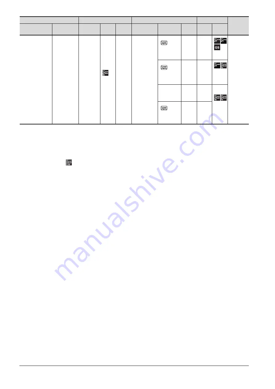
*1
When connected to the Serial communication, the multiple connection function supports only RCPU, QCPU (Q mode), LCPU.
*2
For the connection to GOT, refer to the connection diagram.
➠
*3
For the connection to GOT, refer to the connection diagram.
➠
*4
When a GT10-C02H-6PT9P unit of the sub version A or B is used, do not ground the case of the D-sub (9-pin) connector.
*5
is not support the ACPU connection.
For the system
configuration
between a got and
A plc, refer to the
following.
➠
➠
SERIAL
COMMUNICAT
ION
CONNECTION
*1
RS-232
GT10-
C02H-
6PT9P
*4
-
RS-232
15m
- (Built
into
GOT)
2 GOTs
15m
- (Built
into
GOT)
GT10-
C30R2-
6P(3m)
*3
3m
- (Built
into
GOT)
15m
GT10-
C02H-
6PT9P
*
4
PLC
GOT (1st)
Connection cable
GOT (2nd)
Number of
connectable
equipment
Connection type
Communication
type
Option
device
Model
Option
device
Communication
type
Cable model
Max.
distance
Option
device
Model
Summary of Contents for GOT2000 Series
Page 2: ......
Page 84: ......
Page 432: ...6 58 6 6 Precautions ...
Page 578: ...9 54 9 6 Precautions ...
Page 726: ...12 84 12 5 Precautions ...
Page 756: ......
Page 822: ...14 66 14 4 Device Range that Can Be Set ...
Page 918: ...15 96 15 7 Precautions ...
Page 930: ...16 12 16 6 Precautions ...
Page 964: ......
Page 1002: ...19 38 19 7 Precautions ...
Page 1022: ...20 20 20 5 Precautions ...
Page 1023: ...MULTI CHANNEL FUNCTION 21 MULTI CHANNEL FUNCTION 21 1 ...
Page 1024: ......
Page 1054: ...21 30 21 5 Multi channel Function Check Sheet ...
Page 1055: ...FA TRANSPARENT FUNCTION 22 FA TRANSPARENT FUNCTION 22 1 ...
Page 1056: ......
Page 1223: ......


