background image

Specifying a nested grid in a door/window assembly

Defining Nested Grids

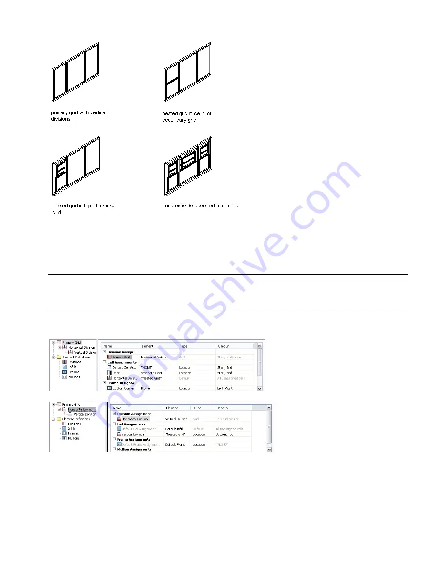
You can define nested grids on the Design Rules tab of the Door/Window Assembly Style Properties dialog box. The
tree on the left side of the tab lists the grids. There is always one primary grid. The primary grid can have one or more
secondary grids. Each secondary grid can have one or more tertiary grids and so on.

TIP To quickly create nested grids in all cells, change the default cell assignment to Nested Grid. If you want multiple levels
of nesting, be sure to change the default cell assignment for each grid. For more information, see 

Creating a Nested Grid

for a Door and Window Assembly

” on page 939

.

Each grid has its own cell assignments. You assign cells to contain another grid, a panel infill, or an object such as a
door or window. For more information, see “

Assigning Infills to Door and Window Assembly Cells

” on page 937.

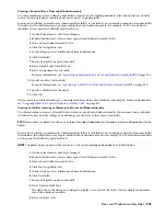
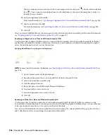
Creating a Nested Grid for a Door and Window Assembly

Use this procedure to create a nested grid, which is a grid within a grid. Each nested grid has its own division rules, cell
assignments, frame, and mullions. By default, the frame is off for nested grids.

For more information, see “

Working with Nested Grids in Door and Window Assemblies

” on page 937.

1

On the Format menu, click Style Manager.

2

Expand Architectural Objects, and expand Door/Window Assembly Styles.

3

Select a door/window assembly style.

Door and Window Assembly Styles | 939

Summary of Contents for 00128-051462-9310 - AUTOCAD 2008 COMM UPG FRM 2005 DVD

Page 1: ...AutoCAD Architecture 2008 User s Guide 2007 ...

Page 2: ... Autodesk Canada Co in the USA and or Canada and other countries Backburner Discreet Fire Flame Flint Frost Inferno Multi Master Editing River Smoke Sparks Stone Wire Third Party Trademarks All other brand names product names or trademarks belong to their respective holders Third Party Software Program Credits ACIS Copyright 1989 2001 Spatial Corp Portions Copyright 2002 Autodesk Inc Copyright 199...

Page 3: ... Crown Copyright 1997 All rights reserved OSTN02 Crown copyright 2002 All rights reserved OSGM02 Crown copyright 2002 Ordnance Survey Ireland 2002 FME Objects Engine 2005 SAFE Software All rights reserved GOVERNMENT USE Use duplication or disclosure by the U S Government is subject to restrictions as set forth in FAR 12 212 Commercial Computer Software Restricted Rights and DFAR 227 7202 Rights in...

Page 4: ...1 2 3 4 5 6 7 8 9 10 ...

Page 5: ...cept 22 Workspace Components 22 The Menu Bar 23 Toolbars 25 Context Menus 26 Tool Palettes 27 Properties Palette 28 AutoCAD Dashboard 28 Drawing Window Status Bar 29 Command Line 30 Application Status Bar 30 Communication Center 31 Project Navigator Palette 31 Changing Workspaces 31 Working with Objects in the Workspace 32 Adding Objects 32 Modifying Objects 33 Selecting Similar Objects 34 Working...

Page 6: ...oordinate Systems 66 In Place Editing 66 In Place Editing of Polyline Based Components 67 In Place Editing of Profile Based Objects and Components 67 In Place Editing of 3D Body Modifiers 69 In Place Editing of Material Hatches 70 Aligning the UCS to an Object Face 71 Isolating Objects 72 Isolating Objects to Edit in a Section View 73 Isolating Objects to Edit in an Elevation View 73 Isolating Obj...

Page 7: ...efresh Options for Linked Tool Palettes 103 Working with Multiple Content Browser Windows 104 Opening a Tool Catalog in a New Content Browser Window 104 Opening Catalog Items in a New Content Browser Window 104 Dragging Catalog Items Between Content Browser Windows 104 Starting the Content Browser from a Windows Command Prompt 105 Chapter 4 Creating and Saving Drawings 107 About Templates 108 Crea...

Page 8: ...ng in a Network Environment 158 Process Overview Working in a Project Environment 158 Project Support Files 159 Working with Design Teams Located Remotely 160 Opening a Project From a Mapped Drive 160 Setting the Default Project Options 161 Creating a Sheet Set Template 162 Creating a Template from an Existing Sheet Set 163 Creating a Template from Existing Drawings 167 The Project Browser 170 Usi...

Page 9: ... Construct to an Element 230 Changing Constructs Interactions with the Project 230 Elements 231 When to Start with Elements 232 Processing Elements in the Building Project 233 Creating a New Element 233 Converting a Legacy Drawing to an Element 234 Opening and Closing an Element 237 Dragging Objects into an Element 237 Changing the Properties of an Element 238 Electronically Transmitting an Elemen...

Page 10: ...d Sheet Sets 279 Archiving a Sheet Set 282 Publishing Sheet Sets 286 Changing Plotting Sheets Interactions with the Project 292 Updating Re path the Project 292 Refreshing the Project View 294 Object Display in External References 294 Using the External Display Configuration 295 Using the External Display Configuration with the Object Enabler 295 Example Displaying Part of the Model as Background ...

Page 11: ...yles from Style Manager 357 Adding Standard Display Settings from Display Manager 358 Synchronizing a Project with the Standards 358 Synchronization Status 360 Synchronizing a Project with AEC Standards 361 Synchronization Exceptions 363 Synchronizing a Project Drawing with AEC Standards 363 Synchronizing Selected Styles and Display Settings with AEC Standards 364 Generating a Synchronization Repo...

Page 12: ...ding Layer Properties in Layout Viewports 409 Identifying Viewport Layer Overrides 410 Removing Viewport Layer Overrides 411 Working with Layer Groups 412 Types of Layer Filters 413 Creating a Group Filter 413 Creating a Property Filter 414 Creating a Layer Standards Filter 416 Adding Layers to Layer Groups 417 Changing the Properties of a Layer Group 417 Renaming and Deleting Layer Groups 418 Con...

Page 13: ...splay Representation for an Object 466 Editing a Display Representation 466 Assigning a Display Representation to a Display Set 467 Comparing Display Representations Between Display Sets 468 Assigning a Display Set to a View Direction 469 Assigning a Display Configuration to a Viewport 470 Specifying a Display Set as a Default Display Set 470 Specifying the Default Display Configuration 470 Specif...

Page 14: ...ls 502 Objects That Support Materials 503 Working with the Material Tool 505 Using the Material Tool to Add Materials to Objects 505 Creating a Material Tool from a Material Definition in Style Manager 506 Copying a Material Tool on a Tool Palette 506 Creating a Material Tool from a Render Material in the Content Browser 507 Applying Material Tool Properties 509 Material Components and Display Pro...

Page 15: ...lette Based and Miscellaneous Annotation Tool Content 569 Part 2 Conceptual Design 573 Chapter 14 Creating Conceptual Models 575 Mass Elements and Mass Groups 576 Using Massing Tools to Create Mass Elements 577 Editing Mass Elements 588 Mass Element Styles 607 Using Massing Tools to Create Mass Groups 612 Using Materials for Mass Elements and Mass Groups 621 Using the Model Explorer to Create Mass...

Page 16: ...hanging the Style of a Wall 666 Changing the Location of a Wall 667 Merging Walls 668 Removing Individual Merge Conditions 668 Removing All Merged Walls 669 Joining Walls 669 Filleting Walls 670 Chamfering Walls 671 Trimming Walls at L and T Intersections 672 Reversing the Direction of a Wall 673 Using AutoCAD Commands to Edit Walls 673 Changing the Roof Line and the Floor Line of a Wall 674 Speci...

Page 17: ...cap Style 744 Applying a Wall Opening Endcap Style to a Wall Style 745 Overriding a Wall Opening Endcap Style on a Wall 745 Using Ortho Close and Close with Walls 745 About Wall Lengths 746 About Curved Walls 746 Specifying Offsets for Roof Line and Floor Line Vertices 746 Specifying the Width and Edge Offset of a Wall Component 747 Chapter 19 Curtain Walls 749 Curtain Walls 750 Using Curtain Wall...

Page 18: ...tep to the Roof Line or Floor Line of a Curtain Wall 835 Changing Vertices in the Roof Line or Floor Line of a Curtain Wall 836 Specifying Gable Settings for a Roof Line 837 Specifying Step Settings for a Roof Line or Floor Line 838 Specifying Vertex Settings for a Roof Line or Floor Line 839 Editing Objects Anchored in Curtain Walls 840 Changing the Orientation of an Object Anchored in a Curtain ...

Page 19: ...n Tools to Create AEC Polygons 979 Creating an AEC Polygon 980 Creating an AEC Polygon with User Specified Settings 980 Creating an AEC Polygon from a Polyline 981 Creating an AEC Polygon from a Profile 981 Creating an AEC Polygon Tool 982 Editing AEC Polygons 982 Using Grips to Edit AEC Polygons 983 Changing the AEC Polygon Style 988 Merging Two AEC Polygons 988 Creating a Hole in an AEC Polygon ...

Page 20: ...024 Attaching Hyperlinks Notes and Files to a Door 1025 Door Styles 1025 Creating a Door Style 1025 Specifying the Dimensions of a Door Style 1027 Specifying the Design Rules of a Door Style 1027 Specifying the Standard Sizes of a Door Style 1028 Creating a Custom Door Shape 1028 Replacing the Door Shape in a Door Style 1029 Editing the Geometry of a Door Style 1029 About Door Display Components a...

Page 21: ...ng and Editing Custom Openings 1113 Creating a Profile for a Custom Opening 1113 Creating an Opening with a Custom Shape 1113 Editing the Geometry of a Custom Opening 1115 Creating an Opening Tool 1116 Editing Openings 1118 Using Grips to Edit Openings 1118 Changing the Shape and Dimensions of an Opening 1119 Flipping an Opening along the X or Y Axis 1119 Changing Endcap Style for an Opening 1120 ...

Page 22: ...5 Stair Interference Conditions 1210 Changing the Alignment of a U Shaped Stair 1219 Changing the Components of a Flight 1220 Changing the Components of a Landing 1220 About the Dimensions of Landing Components 1222 Changing the Extension of a Landing 1222 Specifying Stair Component Display by Cut Plane Elevation 1223 Changing the Display of an Overlapping Stair 1227 Applying Tool Properties to an...

Page 23: ...sions at Landings 1268 Changing the Anchor Properties of a Railing 1269 Specifying Perpendicular Railing Orientation 1270 Changing the Location of a Railing 1271 Applying Tool Properties to an Existing Railing 1272 Attaching Hyperlinks Notes and Files to a Railing 1272 Railing Styles 1272 Creating a Railing Style 1273 Specifying the Upper Rails of a Railing Style 1274 Specifying the Bottom Rails o...

Page 24: ...f Slab Context Menu Tools 1332 Creating a Clipped Gable Roof 1347 Creating a Dormer in a Roof Slab 1348 Slab and Roof Slab Styles 1349 Creating a Slab or Roof Slab Style 1350 Specifying the Components of a Slab or Roof Slab Style 1351 Specifying the Materials of a Slab or Roof Slab Style 1355 Specifying the Display Properties of a Slab or Roof Slab Style 1357 Adding Classifications to a Slab or Ro...

Page 25: ... Member 1419 Attaching Hyperlinks Notes and Files to a Structural Member 1420 Working with Structural Member Body Modifiers 1420 Adding a Body Modifier to a Structural Member 1420 Subtracting a Body Modifier from a Structural Member 1421 Replacing a Structural Member with a Body Modifier 1422 Editing the Geometry of a Body Modifier 1423 Managing Body Modifiers 1424 Restoring a Body Modifier to a M...

Page 26: ...ume Anchors 1468 Changing the Position and Size of Objects Anchored to Volumes 1469 Anchoring Objects to a Different Volume 1470 Copying Objects to All Layout Volumes 1470 Releasing and Positioning Anchored Objects 1471 Releasing Anchored Objects 1471 Positioning Anchored Objects 1471 Creating an Anchor Tool 1471 Chapter 31 Layout Curves and Grids 1473 Layout Curves and Grids 1474 Using Layout Cur...

Page 27: ...Grid Boundary or Limits 1504 Dimensioning Column Grids 1504 Editing Column Grids 1505 Changing the Dimensions of a Column Grid 1505 Changing the Lines of a Column Grid 1505 Attaching Clipping Profiles to Column Grids 1509 Attaching Hyperlinks Notes or Files to a Column Grid 1510 Changing the Location of Column Grids 1510 Changing the Display of Column Grids 1511 Changing the Node Radius Display of...

Page 28: ...cks 1548 Adding a Mask Block 1548 Adding a Mask Block with User Specified Settings 1549 Creating a Mask Block from Polylines 1549 Creating a Mask Block Tool 1550 Attaching Mask Blocks to Objects 1551 Detaching Mask Blocks from Objects 1552 Editing Mask Blocks 1552 Using Grips to Move Mask Blocks 1552 Changing the Location of a Mask Block 1553 Editing the Profile of a Mask Block 1553 Applying Tool ...

Page 29: ...e Spaces 1598 Activating and Deactivating Automatic Updates 1599 Manually Updating Associative Spaces 1600 Merging Associative Spaces 1601 Dividing an Associative Space 1603 Changing the Associativity of a Space 1604 Troubleshooting Generating Associative Spaces 1605 Creating Non Associative Spaces 1612 Drawing a Non Associative 2D or Extruded 3D Space 1612 Converting Objects Profiles and Polyline...

Page 30: ...nd Files to a Space Style 1693 Converting Area Styles to Space Styles 1694 List Definitions 1695 Creating a List Definition 1695 Specifying the Application for a List Definition 1696 Editing a List Definition 1696 Attaching Notes and Files to a List Definition 1697 Zones 1697 Using Zone Tools to Create Zones 1698 Zone Properties 1699 Creating a Zone 1700 Creating Zones with User Specified Settings...

Page 31: ...749 Implementing Offset Rules 1754 Chapter 37 Sections 1765 Sections 1766 Process Overview Creating a 2D or 3D Section 1769 Process Overview Creating a Live Section View 1771 Drawing and Editing Section Lines 1771 Drawing a Section Line and Marks 1772 Changing the Height of a Section Using Grips 1773 Changing the Lower Extension of a Section Using Grips 1774 Changing the Length of a Section Using ...

Page 32: ... Height of an Elevation Using Grips 1814 Changing the Lower Extension of an Elevation Using Grips 1814 Changing the Length of an Elevation Using Grips 1815 Changing the Angle Dimensions of an Elevation 1816 Creating Graphic Subdivisions for 2D and 3D Elevations 1816 Changing Elevation Mark Attributes 1817 Changing the Location of an Elevation Line 1817 Modifying an Elevation Line Using Grips 1817 ...

Page 33: ... Dimensions Using AEC Dimension Tools 1854 Creating an AEC Dimension 1855 Creating an AEC Dimension with User Specified Settings 1855 Use Cases for AEC Dimensions 1857 Converting an AutoCAD Dimension to an AEC Dimension 1861 Copying Properties of AEC Dimensions to AutoCAD Dimensions 1862 Creating an AEC Dimension Tool 1863 Editing AEC Dimensions 1863 Adding Points to an AEC Dimension 1864 Detachin...

Page 34: ...891 Attaching Hyperlinks Notes or Files to an Elevation Label 1892 Creating User Defined Elevation Labels 1892 Creating a Graphic Symbol 1893 Adding Attributes 1893 Creating a Block 1893 Creating a Multi View Block 1893 Adding the Elevation Label to the AutoCAD DesignCenter 1894 Chapter 42 Fields 1895 Fields Overview 1896 Inserting Fields 1897 Inserting Fields in a Drawing 1897 Inserting Fields in...

Page 35: ... Mark 1956 Creating a Block Based Annotation with a Leader 1957 Editing a Text Based Annotation 1957 Editing a Masking Break Mark 1958 Editing a Block Based Annotation 1958 Keynoting Tools 1959 Configuring the Annotation Tool for Keynoting 1959 Using Keynote Insertion Tools 1961 Using Keynote Legends 1963 Viewing and Editing Keynotes in a Drawing 1968 Specifying Keynotes 1971 Working with Keynote ...

Page 36: ...t 2037 Releasing an Anchored Schedule Tag 2037 Viewing the Connection Between Tags and Objects 2038 Renumbering Property Set Data 2038 Managing Schedule Tables 2039 Working with Schedule Table Styles 2039 Exporting a Schedule 2052 Exporting Schedule Data for Selected Objects 2052 Specifying the Display Properties of a Schedule 2053 Changing General Schedule Properties 2053 Changing the Selection C...

Page 37: ...ions 2095 Changing the List Item for an Object 2095 Attaching Notes or Reference Files to a List Definition 2095 Classification Definitions 2096 Process Overview Including Classification Data in Schedules 2097 A Classification Use Case 2097 Creating a Classification Definition 2099 Specifying the Object Types for a Classification Definition 2100 Adding Classifications to a Classification Definitio...

Page 38: ...ing Custom AEC Content 2120 Using the AEC Content Wizard 2120 Editing AEC Content 2128 Modifying DesignCenter Content with the AEC Content Wizard 2128 Modifying Fixture Layouts 2128 Turning Off the Dimension Scale Override 2128 Part 6 Other Utilities 2131 Chapter 48 Cameras 2133 Adjusting the Camera Position 2134 Chapter 49 Converting Objects to 3D Solids 2135 Converting Objects to 3D Solids 2136 ...

Page 39: ... Layer Keys 2171 Removing Unnecessary Objects 2171 Chapter 53 Migrating Detail Component and Keynote Databases 2173 Migrating Your Database Modifications 2174 Running the Detail Component Keynote Database Migration Utility 2175 Index 2187 Contents xxxix ...

Page 40: ...xl Contents ...

Page 41: ...Workflow and User Interface 1 1 ...

Page 42: ...2 Chapter 1 Workflow and User Interface ...

Page 43: ...e new AutoCAD 2008 platform this release is targeted at making the transition from AutoCAD to AutoCAD Architecture easier by simplifying your interactions with the software It offers many new features that help you achieve your design and documentation goals 1 3 ...

Page 44: ...ents Annotation Scaling Annotation scaling allows you to plot annotation at the same height or size regardless of the viewport zoom scale Annotation scales can be associated with annotative objects in AutoCAD Architecture so that these objects can be sized properly for specific annotation scales in model space and displayed correctly in paper space You can also specify whether to display or hide a...

Page 45: ...ayer Overrides You can now apply overrides for color linetype lineweight and plot style to layers in individual layout viewports This is an efficient way to display objects with different property settings in individual viewports without changing their ByLayer or ByBlock properties Because layer property overrides do not change the layer s global properties you can have objects display differently...

Page 46: ...palette For more information see Using the Properties Palette to Change Display Properties on page 445 IFC Certification The Industry Foundation Classes IFC file format provides an interoperability solution between different software applications It complies with established international standards for importing and exporting building objects and their properties IFC improves communication product...

Page 47: ...ive You can set up your project so that the sheet view layer settings are updated from the layer settings in the model space of the view drawing The synchronized settings include the layer states on off thawed frozen and the layer properties layer color linetype plot style of layers native to the view drawing as well as layers in external references attached to the view drawing through constructs ...

Page 48: ...drawings and revisions is key as you move through the design development and construction phases of a project You can visually compare versions of drawings and review proposed changes with the Drawing Compare feature Drawing Compare also allows you to compare drawings from AutoCAD AutoCAD Architecture AutoCAD MEP Revit Architecture and Revit Structure For more information see Drawing Compare on pa...

Page 49: ... exported to AutoCAD MEP For more information see Working with Surface Openings on page 1662 Area calculation standards Offsets between space boundaries can be automatically determined by an area calculation standard specified in the drawing The space boundaries are calculated according to the area calculation standard Predefined standards shipped with the Subscription Module Spaces and Drawing Co...

Page 50: ...e structural member styles so that members trim automatically to other members during edits rather than only during initial placement A Quick Start forTransitioning from AutoCAD to AutoCAD Architecture If you have previously accomplished your architectural tasks with AutoCAD and want to transition to using AutoCAD Architecture you will find that using tools specifically designed for architects pro...

Page 51: ... Mass Groups Solids Design Massing Studies Online Help Mass Elements and Mass Groups on page 576 Create a Space Layout and Colored Plans Visualization Group Visual Styles Palette Visual Styles Visual Styles Create Presentation Graphics Online Help Use a Visual Style to Display Your Model in the AutoCAD Help Design Group Spaces Palette Spaces Polyline and Hatch Create Space Plans Online Help Space ...

Page 52: ...amic Blocks Draw Windows Online Help Windows on page 1057 Design Group Design Palette NOTE More Stair tools can be accessed from Content Browser Stairs Linework Draw Stairs Online Help Stairs on page 1133 Design Group Design Palette NOTE More Railing tools can be accessed from Content Browser Railings Linework Draw Railings Online Help Railings on page 1252 Design Group Design Palette NOTE More Cu...

Page 53: ...AutoCAD tools How do I Design Group FF E Palette Multi View Blocks Blocks or Dynamic Blocks Place Furniture Fixtures and Equipment Online Help Multi View Blocks on page 1558 Create Annotation and Scheduling A Quick Start for Transitioning from AutoCAD to AutoCAD Architecture 13 ...

Page 54: ...edule Tables on page 2039 Learning Movie Creating Schedules Style Manager Property Set Definitions Attributes Modify Block Properties for Scheduling Data Online Help Property Set Definitions on page 2069 Document Group Callouts Palette Callouts and Project Navigator Xclip Create Enlarged Plans Online Help Working with Callouts on page 1990 Document Group Callouts Palette Sections Linework Extract ...

Page 55: ...p drawing revisions Online Help AEC Content in the Content Browser on page 2116 Add Details and Keynotes Detailing Group Detail Components Linework Create Details Online Help Detail Components on page 1917 Learning Movie Detailing Your Designs Document Group Annotation Palette Keynoting Leaders Annotate Details Online Help Keynoting Tools on page 1959 Work in a Project A Quick Start for Transition...

Page 56: ... desktop if you chose to create it when you installed the software On the Start menu click Programs Autodesk AutoCAD Architecture 2008 AutoCAD Architecture 2008 NOTE AutoCAD Architecture 2008 can be run under Windows 2000 Windows XP and Windows Vista Customizing Startup You can use command line switches in the properties of the desktop icon to specify AutoCAD Architecture startup options Run a sta...

Page 57: ...uction to the concepts of working with AutoCAD Architecture 2008 AutoCAD Architecture 2008 Printed Getting Started Guide A set of exercises designed to give you an overview of the capabilities and features of AutoCAD Architecture AutoCAD Architecture 2008 Online Tutorials Gives an overview of the new features in AutoCAD Architecture 2008 AutoCAD Architecture 2008 New Features Workshop View these m...

Page 58: ...displayed click the AutoCAD Help book on the Contents tab and then browse the contents to locate the information you need Or use the Index or Search tabs to find specific topics To access AutoCAD 2008 New Features Workshop 1 On the Help menu click Help 2 When the Help window is displayed click the AutoCAD Help book and then click the New Features Workshop link under General Information AutoCAD Arc...

Page 59: ...e AOTC is developed by Autodesk Autodesk Authorized Training Courseware AATC is developed by Autodesk partners including titles in a growing number of languages Autodesk Official Certification Courseware AOCC teaches the knowledge and skills assessed on the Certification examinations Visit http www autodesk com aotc to browse the Autodesk Courseware catalog Autodesk Certification Gain a competitiv...

Page 60: ... your local reseller or check the frequently asked questions Technical Solutions FAQS section and Discussion Groups on the website for AutoCAD Architecture at http www autodesk com support News groups are another good source of information You can look through the questions that have already been posted or you can post your own questions Feedback Please let us know what you think Whether you have ...

Page 61: ... architectural professionals The topics in this section provide an overview of the available workspace components and describe how to access and configure them to meet your needs For detailed instructions on using workspace components to create and edit architectural objects refer to the relevant object specific topics in Help Walls Doors Windows and so on 2 21 ...

Page 62: ...can reconfigure it according to your preferences as you work You can move or hide various components as needed display additional toolbars or add new tools and tool palettes If desired you can save your customizations as a new workspace that you can access for later drawing sessions You can also switch from one workspace to another at any time by selecting a new one from the drop down list on the ...

Page 63: ...cribed individually in the following topics The Menu Bar The menu bar of the drawing window provides the following pulldown menus each of which includes a group of commands that support a particular aspect of the architectural workflow Where applicable menu options show alternate access methods such as a toolbar button or a keyboard shortcut Contents Menu File Drawing transmittal and publishing co...

Page 64: ...le the instruction for selecting the Sheet Keynotes option on the Keynote Display submenu of the View pulldown menu would be Select View menu Keynote Display Sheet Keynotes In addition to the standard pulldown menus described above you can load any of the following pulldown menus by selecting them from the Window menu Contents Menu Similar to the Design menu in previous versions of the software De...

Page 65: ...r is positioned outside of the toolbar area You can also dock toolbars to an edge in the drawing area hide them resize them or create your own For detailed instructions on customizing the display of toolbars see the Toolbars topic in the AutoCAD Help The following toolbars are displayed in the toolbar area by default Workspaces Standard Navigation Layer Properties Shapes Draw Order Modify To displ...

Page 66: ... for changing color linetype lineweight and linetype scale for an object Properties Commands for working with external references in the drawing Refedit Light Material and Render commands Render Commands for different shade modes Shading Commands for setting and changing the UCS of the drawing UCS UCS II Commands for switching between 2D and 3D views of the drawing View Viewpoint Commands for spec...

Page 67: ...including the same commands available from the Modify toolbar General drawing context menu Tool Palettes Tool palettes provide the main method for accessing tools to create objects in your model You can have tools for standard objects as well as for objects with specific styles and properties Tool palettes are organized by tool palette groups in a tool palettes set You can create your own tool pal...

Page 68: ...erties Palette For more information see The Properties Palette on page 56 AutoCAD Dashboard The dashboard is a special palette that displays buttons and controls that are associated with a task based workspace and it is used primarily for 3D modeling viewing and rendering The dashboard provides a single interface element for modeling and rendering operations It eliminates the need to display many ...

Page 69: ...or Construct For more information see Drawing Management on page 149 Annotation Scale When working with viewports you can select a new annotation scale for the current viewport from the drop down list of available scales Click to show annotative objects for all scales Click to automatically add scales to annotative objects when the annotation scale changes Level of Detail Shows the current display...

Page 70: ...ormation see The Project Status Bar on page 202 The application status bar gives access to these settings Cursor coordinate values Controls the coordinate format as either relative or absolute Snap On Off Settings Grid On Off Settings Ortho On Off Polar Tracking On Off Settings Object Snap OSnap On Off Settings Object Track OTrack On Off Settings Dynamic UCS With the dynamic UCS feature you can te...

Page 71: ...ther important information at specified intervals Alternatively you can update on demand When new updates are available the Communication Center icon displays with a yellow exclamation mark When you click the icon the Communication Center is displayed allowing you to download the latest updates To specify the update properties click the Communication Center icon and click Settings Communication Ce...

Page 72: ...f the following from the drop down menu Design Provides all the basic tools for creating architectural objects in your drawings Document Provides tools for adding schedule tables annotations callouts and other documentation objects to your drawings Detailing Provides tools for inserting a wide variety of predefined detail components as well as tools for detail drafting Visualization Includes all t...

Page 73: ...s palette The Properties palette is the central location for entering and changing information about an object This palette has categories that correspond to the tabs in the Properties dialog boxes from earlier releases of the software For detailed information see The Properties Palette on page 56 Modifying a wall with the Properties palette Context menu Right click the object to display its avail...

Page 74: ...t sections Window grips for direct editing Selecting Similar Objects Use this procedure to create a selection set of objects on the same layer and that have the same style You may want to select a number of objects that are on the same layer and that have the same style in order perform a global change The QSELECT command allows a single selection criterion like layer or style With the Select Simi...

Page 75: ...ditionally you can add remove and rearrange palettes and groups in the set You can add tool palettes to the tool palettes set from a tool catalog For example you could create one tool palette set for imperial tools and another for metric tools For more information see Specifying Different Tool Palettes for the Tool Palettes Set on page 38 Only one tool palettes set can be active during an AutoCAD ...

Page 76: ...ocess and enhances consistency across a project For example you might define a wall tool that contains the style CMU 8 Furring and that has automatic cleanup and a baseline offset of 1 Whenever you add a wall with this tool the wall has the style CMU 8 Furring it cleans up automatically and it has an offset of 1 For more information see Tools on page 44 Tool Palettes and the Content Browser When m...

Page 77: ...idden when you move the cursor away from it leaving only the title bar visible When you move the cursor over the title bar the tool palettes set is re displayed Tool palettes set hidden left and re displayed right 1 In the title bar of the tool palettes set click Auto hide The tool palettes set is hidden except for the title bar 2 To re display the tool palettes set move the cursor over the title ...

Page 78: ...owse and browse for a folder containing the desired tool palette Add paths to all additional tool palettes to be included in the tool palettes set of this profile 3 Click OK Creating a NewTool Palettes Set Use this procedure to create a new tool palettes set 1 Create a folder in which you will create the new tool palettes set The default tool palettes set is in Documents and Settings Username Appl...

Page 79: ...e 49 add a tool to a palette The changes you make are saved to the tool palettes set in the new profile you created To revert back to your original tool palettes set select your original profile in the Options dialog box Creating a NewTool Palettes Group Use this procedure to create a new tool palettes group 1 In the title bar of the tool palettes set click and then click Customize Tool Palettes 2...

Page 80: ... the settings you specify for the overall tool palettes set as described in Controlling the Appearance of the Tool Palettes Set on page 37 and the settings you specify for individual tool palettes In the tool palettes set you specify the transparency size position and auto hide of the tool palettes set On the tool palette you specify the size of tool images and their arrangement on the tool palett...

Page 81: ...lette and click View Options 3 In the View Options worksheet select the desired View style Then If you want to select Icon only for View style view only tool icons select Icon with text for View style view tool icons and tool text select List view for View style view tool icons and tool text in a single column list 4 To apply these changes to all palettes in the tool palettes set select All Palett...

Page 82: ... edit the text as necessary 6 To delete a separator line or a text annotation select the separator line or text right click and click Delete Working withTool Palettes from a Central Location When multiple users are working on a large project consistency of tools is especially important Typically the objects for the project and their styles and properties are set up by a CAD manager or system admin...

Page 83: ...each palette then position the eyedropper over any of the selected palettes 6 Drag the palette to the tool palettes set in the AutoCAD Architecture workspace The tool palette is dropped into the tool palettes set 7 Right click on the palette and click Properties The text below the check box displays the name of the catalog in the Content Browser from which the palette is updated If you click that ...

Page 84: ...resh Palette NOTE You can also update the whole palette set by clicking in the tool palettes set and then clicking Refresh Palette Set This command updates all linked tool palettes in the tool palettes set Tools Tools represent the individual objects you can add to a drawing A tool contains creation parameters for the object it represents When you add an object with a specific tool the object has ...

Page 85: ...ect properties for example a wall tool might have the style Brick 4 Brick 4 Object tools Command tools are a graphical representation of an object related command For example the Browse Property Data tool opens a dialog box for browsing the property data of all objects in a drawing the Renumber Data tool renumbers property data in selected property sets by increment or by a user defined number You...

Page 86: ... insert the object 6 Follow any additional prompts as required to insert the objects in the drawing and then press ENTER Changing theTool Properties Use this procedure to change the properties of a tool on a tool palette You can set these general properties for an object tool Tool name Tool description also used as the tooltip and as the tool description when the copied to a tool catalog in the Co...

Page 87: ...f the location is other than the current drawing to select an object style 10 Add object specific properties NOTE When you click a property to enter a value the value underneath the current property is hidden and the property field is highlighted Enter a value for the current property in the appropriate location 11 Click OK Changing aTool Icon Use this procedure to change the icon of a tool A new ...

Page 88: ...object in the drawing select the tool in the tool palette right click and Set Image from Selection Then select the object in the drawing you want to use as a tool icon and press ENTER The tool icon is created with the last used view direction and display configuration set in the viewer of the properties of this tool type For example if the tool viewer of the last used wall is set to Top view and t...

Page 89: ...he Standard style 2 Open the tool palette where you want to create the new tool 3 Select the object and drag it to the tool palette 4 Define additional properties for the tool if necessary For more information see Changing the Tool Properties on page 46 Copying aTool from aTool Palette Use this procedure to copy a tool from one tool palette to another 1 Open the tool palette that contains the tool...

Page 90: ...nging the Tool Properties on page 46 Creating aTool from AEC Content in DesignCenter Use this procedure to create a tool on a tool palette from an AEC Content item in DesignCenter NOTE You can also create tools from blocks in DesignCenter but they have slightly different tool options You can drag and drop AEC content items from a DesignCenter folder to a tool palette For more information on creati...

Page 91: ...s for the tool if necessary For more information see Changing the Tool Properties on page 46 Creating a CommandTool Use this procedure to create a tool for a command in AutoCAD Architecture Command tools are a graphical representation of an object related command For example the Browse Property Data tool opens a dialog box for browsing the property data of all objects in a drawing the Renumber Dat...

Page 92: ...ent Browser to store and organize catalog tools in a central location A number of stock tools are available in the AutoCAD Architecture Stock Tool Catalog Additionally sample catalogs contain tools with styles from the Styles drawings You can copy these tools to a tool palette and modify them You can also create your own tool palettes and tools in a catalog in the Content Browser copy them to a to...

Page 93: ...he tool so that the pointer image changes to an eyedropper To copy multiple tools press and hold CTRL while clicking each tool then position the eyedropper over any of the selected tools You can also select all the tools in the current category by right clicking and clicking Select All 4 Drag the eyedropper to a tool palette in the tool palettes set 5 To refresh the tool select it right click and ...

Page 94: ...tecture For example perhaps you have a tool in the Content Browser that adds a Box mass element of 3 x 3 x 3 meters You want to change the tool so that it adds a Box mass element of 4 x 4 x 4 meters You would first link the mass element tool from the Content Browser to a tool palette in AutoCAD Architecture Then temporarily deactivate the link and change the dimension properties of the tool to 4 x...

Page 95: ...rlier releases of the software you used the Match command to do this Apply the properties of a tool to a different object type Using this method you convert the object to an object of the same type as the tool For example when you apply the properties of a wall tool to a polyline the polyline is converted to a wall with the settings defined in the wall tool Depending on their type various object t...

Page 96: ...dding a Tool Palette from a Tool Catalog in the Content Browser on page 43 you cannot delete individual tools from it To delete the tool delete it from the palette in the Content Browser and then update the palette in AutoCAD Architecture as described in Updating a Tool Palette from a Tool Catalog in the Content Browser on page 44 1 Open the tool palette that contains the tool you want to delete 2...

Page 97: ... the new position of the Properties palette 3 Release the Properties palette at the correct location Hiding the Properties Palette Use this procedure to hide the Properties palette when it is not in use The Properties palette can be configured to hide when you move the cursor away from it leaving only the title bar visible When you move the cursor over the title bar the Properties palette is re di...

Page 98: ...available depend on the object you are editing Dimensions Most objects in AutoCAD Architecture have dimension settings for width height and other basic features Many objects have additional settings and the option to use AutoCAD QuickCalc A wall for example has additional length and baseline justification settings and you can use QuickCalc to calculate and apply a new rotation For more information...

Page 99: ...e Display Tab or show it if it is currently hidden enter the following command on the command line AecChangeDisplayTabStatus Display properties on the Display tab The Extended DataTab The Extended Data tab of the Properties palette contains the following object properties Hyperlink You can add a hyperlink to an object For more information see Add Hyperlinks to a Drawing in AutoCAD Help Text Notes ...

Page 100: ...ly when they are launched from a palette or from an object They cannot be accessed from the pulldown menus as they always refer to a specific object or object tool Opening the Anchor worksheet A worksheet is a modal dialog that must be closed before continuing to work in the drawing Direct Editing with Grips and Dynamic Dimensions You can make design changes in the workspace without using dialog b...

Page 101: ...s depending on the current view For example a structural beam has an additional Roll grip in Model views that is not visible in Plan views Because rolling a beam is a 3D operation that you can perform only in an isometric view it makes no sense to display the Roll grip in Plan views Similarly roof and floor line grips are useful only in a 3D view therefore they are displayed only in Model views Cu...

Page 102: ...property of any object Auxiliary Gray Different grip types display in different colors in an in place editing session You can change the color of these grips on the AEC Editor tab in the Options For more information see Changing the AEC Editor Settings on page 115 Using the CTRL Key with Grips Some object grips have multiple functions For example a face grip on a free form mass element has these p...

Page 103: ...de for the curtain wall grid Selecting the Edit In Place grip in an AEC dimension activates additional grips for the individual dimension chains text strings and extension lines A trigger grip typically displays with a circle or an arrow AEC dimension before and after activatingTrigger grip In some cases such as with the AEC Dimension trigger grip the grip edit mode is exited when the object is no...

Page 104: ...mensions to change window width These dynamic dimensions give you instant feedback about your changes You can also use the dynamic dimensions to enter new dimension values directly on screen 64 Chapter 2 The Workspace ...

Page 105: ...or more information see Changing the AEC Editor Settings on page 115 NOTE When a dimension edit box is displayed pressing ENTER sets the value of the property that you are editing and ends the grip operation Pressing TAB sets the value changes the focused dimension and continues the same grip editing operation NOTE When one or more editable dimensions are displayed you can always press TAB to a st...

Page 106: ...are frozen To access the commands and objects again exit the in place editing mode When you enter an in place editing session a temporary in place edit profile is drawn around the object being edited After making changes you exit the in place edit session and save the changes You may also discard changes upon exiting the in place session and the object reverts to the state it was in before the in ...

Page 107: ... component in a 3D view the UCS is aligned to the component so that you can easily add or remove vertices and grip edit the component The editing commands available for polyline based components are listed on the context menu of the in place editing profile To access the context menu select the in place editing profile and right click The commands for editing polyline based objects vary depending ...

Page 108: ...s of rails and posts in railings In place edit profile on extruded mass elements NOTE In place editing for the objects in the previous list is available only if one or more components of the object are based on profiles For example if you have a railing for which no rails or posts are based on profiles the in place editing command is not available However if one or more railing components are base...

Page 109: ... Save Changes saves the changed geometry to a new profile definition Save as New Profile discards all changes to the geometry of the profile and reverts to the profile shape before the in place edit session Discard All Changes changes the display of the in place edit profile you can change the display of the profile boundary the profile hatch and for polyline based profiles the display of the modi...

Page 110: ...difier and reverts to the body shape before the in place edit session Discard All Changes changes the display of the in place edit profile Edit Object Display In Place Editing of Material Hatches You can make changes to the surface hatch of an object with an in place edit profile provided the surface hatch is coming from a material Unlike the other in place edit types you do not change the shape o...

Page 111: ... with in place editing Aligning the UCS to an Object Face Use this procedure to align the currently active UCS to the face of an object You can align the UCS to the face of an AEC object or to the face of an AutoCAD solid For detailed information about the UCS see Use Coordinates and Coordinate Systems in AutoCAD Help For more information about working with objects in a temporary section elevation...

Page 112: ... is aligned to the object face Isolating Objects AutoCAD Architecture offers an easy to use feature for temporarily hiding and displaying selected objects in your drawing This feature is useful when you want to focus on individual areas of your drawing You can perform the following operations with the Isolate Objects feature Create an object selection set to hide or display Fine tune the selection...

Page 113: ...ction view When you isolate objects to look at them in a section view other objects in the drawing are hidden from view as you work You must save your drawing after you exit Edit In Section 1 Select the objects you want to edit right click and click Isolate Objects Edit In Section The Edit in View Toolbar opens 2 Specify the first and second points for the section line or press ENTER to change the...

Page 114: ...h many objects and need to display only a small number of them Displaying only a chair and a cabinet in a drawing You can work with the Isolate Object command from the context menu of an object or from the drawing window status bar Isolate Objects command on the drawing window status bar 1 Select the objects in the drawing that you want to isolate and display 2 Right click and click Isolate Object...

Page 115: ...dden or whether all objects are displayed in the drawing When you have isolated objects in your drawing the light bulb on the right side of the drawing window status bar is displayed in red When all objects are displayed and none are isolated or hidden the light bulb is displayed in yellow Alternatively to ascertain that no objects are hidden select an object in the drawing right click and click I...

Page 116: ...ts in External References When you are working with external references you can hide and isolate objects Consider the following points You can isolate an external reference within a host drawing as a whole by selecting it and isolating at as described in Isolating Objects to Display on page 74 You can isolate individual objects within an external reference by opening the external reference isolati...

Page 117: ...les AutoCAD Architecture 2008 Sample Sample Palette Catalog Imperial Metric Sample Tool Palette Catalogs Program Files AutoCAD Architecture 2008 Sample Autodesk Render Material Catalog Sample Render Material Catalog Integration of AutoCAD Architecture and AutoCAD AutoCAD Architecture is integrated with the AutoCAD design platform The commands and features of both applications are blended within th...

Page 118: ...elta symbol Units Running the UNITS command from the command line opens the AutoCAD Architecture Drawing Setup dialog If you want to open the AutoCAD Units dialog enter ddunits on the command line WARNING To change the drawing setup of AutoCAD Architecture you must use the Drawing Setup command of AutoCAD Architecture If you change the units in the AutoCAD Units dialog box AutoCAD Architecture dra...

Page 119: ...wser lets you store share and exchange AutoCAD Architecture content tools and tool palettes The Content Browser runs independently of the software allowing you to exchange tools and tool palettes with other Autodesk applications 3 79 ...

Page 120: ...toCAD Architecture user has a personal catalog library Tool catalog data is not stored in the catalog library Rather the catalog library contains pointers to the physical tool catalogs It is like the card catalog in a real library it tells you where to find a book but it does not contain the book itself You can sort the catalogs in the library by Last Used Publisher Title or Type You can filter th...

Page 121: ...ay the top level of the catalog library in the right pane This view is either all the catalogs in the library or a group of catalogs filtered by type You can have more than one instance of the Content Browser open at a time To open an additional Content Browser window press CTRL N For more information see Working with Multiple Content Browser Windows on page 104 Viewing aTool Catalog To view a too...

Page 122: ... palette or tool package You can modify the contents and properties of a tool catalog if you are authorized to do so unless the catalog is read only Read only tool catalogs are identified in the Content Browser title bar when you open the catalog A tool catalog category may contain more items than can fit on a page If multiple pages are needed navigation controls appear at the top and bottom of ea...

Page 123: ... into the drawing area with the i drop icon to begin adding an Arch mass element to your drawing AutoCAD Architecture tool palette set with added tool palette If you use a tool frequently you will save time if you add the tool to a palette in the tool palette set where you can access it without using the Content Browser ManagingYour Catalog Library You manage your catalog library by adding and del...

Page 124: ... The tool catalog is displayed in the catalog library with the following default graphic image For information about changing the graphic image and other tool catalog properties see Editing Tool Catalog Properties on page 90 Creating aTool Catalog from Content Drawings Use this procedure to create a new tool catalog based on existing standards from the styles in one or more drawings You specify th...

Page 125: ...tools will be placed in categories or palettes named Walls Doors etc NOTE If both options are enabled the catalog is first grouped by the drawings and then by the object type generating categories from the drawings and palettes from the object types This is implemented because palettes cannot be nested In this case the radio buttons for categories and palettes are disabled and the Create tools in ...

Page 126: ...ools in one Tool Catalog Generator session Instead break up the source drawings and use multiple instances of Tool Catalog Generator to achieve the conversion 1 Click CAD Manager menu Tool Catalog Generator NOTE If the CAD Manager menu is not visible in your menu bar click Window menu Pulldowns CAD Manager Pulldown 2 Under Catalog select Add to an existing catalog 3 Enter the name and the path of ...

Page 127: ...talog To organize the new tools in categories select Create Tools in Categories If you have selected to group tools by their source drawing then for each source drawing a category will be created If you have selected to group tools by their object type then for each object type a category will be created To organize the new tools in palettes select Create Tools in Palettes If you have selected to ...

Page 128: ...e catalog and all its affiliated files can be accessed by all users to whom you want the catalog distributed 3 Shift Rightclick the catalog 4 Click Convert to Registry File Then If you want to browse to the desired folder location enter a name for the registry file and click Open In that case a new registry file REG is created containing the registry information for the selected catalog create a n...

Page 129: ...y tool dependent files into the above folder to be referenced by the publish catalog the feature attempts to copy all of the dependent files referenced in the catalog to the dependent file location you specify If you do not select this option you must verify that the files are already present in the dependent location If you select the option Report invalid catalog references the feature generates...

Page 130: ...ick OK The link to the website is represented in the catalog library by a default graphic image which you can change For information about changing this image and other Tool Catalog properties see Editing Tool Catalog Properties on page 90 Opening Web Pages in the Content Browser Use this procedure to open a web page through a website link in your catalog library TIP If you have any problem viewin...

Page 131: ... on linking tools to the Content Browser see Using Tool Catalog Items in AutoCAD Architecture and Working with Tools from a Central Location on page 52 define that tools and palettes from this catalog should be automatically linked to the Content Browser when dropped onto the tool palettes set of AutoCAD Architecture 2008 clear Link items when added to workspace Inserting tools without retaining a...

Page 132: ...he right pane of the Content Browser position the pointer over Filter in the left pane 3 From the list of available types click the type of catalog you want to view To display all the catalogs in the library click All Catalogs NOTE To filter catalogs by Type you must assign a type to each catalog in the library For more information see Creating Catalog Types on page 91 Removing aTool Catalog or We...

Page 133: ...ords you specify Name Description Keywords The Search tool is only as helpful as the tool names and descriptions that you assign A tool name should indicate the tool s function and the description should indicate the tool s use If you enter a search term containing more than one word the Search feature looks for items containing both words You can also join multiple search words with AND or To ret...

Page 134: ...m clear search for tools anywhere in the open catalog 2 Enter the terms to search for under Search 3 Click GO Items that match your search criteria are displayed in the right pane of the Content Browser To go to the catalog containing an item click that item To view the source catalog of an item right click the item 4 To perform another search click the button located near the top of the left pane...

Page 135: ...ace Boundary Structural Members and Column Grid Drafting Tools AEC Dimensions Callouts and Title Mark Text Leaders Keynotes Legend Masking Block Hatching and Gradient Chamfer and Fillet Shrink Wrap Tool Welding Symbols Helper Tools AEC Entity Reference AEC Polygon Camera Horizontal and Vertical Design Sections Hidden Line Removal Tool and Napkin Sketch Measurement Tools Area Distance and Point ID ...

Page 136: ... Package Properties dialog box To view the dialog box right click the tool package and click Properties For information about other tool package properties see Adding a Tool Package to a Tool Catalog on page 97 CustomizingTools You customize a tool by copying it to a palette in the AutoCAD Architecture 2008 tool palette set modifying the tool s properties and then copying it back to its original l...

Page 137: ...ch of the tool catalog enter a publisher identify the publisher of the tool palette Adding aTool Package to aTool Catalog Use this procedure to add a tool package to a tool catalog You must have write access to the tool catalog in order to add a package 1 In the Content Browser open the tool catalog in which to add the tool package To add the package to a specific category in the catalog open that...

Page 138: ...copying to You can also open multiple Content Browser windows and drag tool palettes and tool packages from one window to another For information about using multiple windows to copy and move items see Dragging Catalog Items Between Content Browser Windows on page 104 1 Open the tool catalog containing the tool palette or tool package to copy or move If the item is located in a specific category o...

Page 139: ...ool catalog to open it 5 Open the destination of the tool Then If the destination is open the category a category of the tool catalog open the category for that tool palette if necessary and then click the tool palette a tool palette in the tool catalog open the category for that tool package if necessary and then click the tool package a tool package in the tool catalog 6 In the right pane of the...

Page 140: ... be used immediately in the drawing area or stored in a palette in the tool palette set You can add a catalog tool palette or tools in a tool package to the tool palette set TIP To keep the Content Browser window in view while other applications are active right click the title bar of the Autodesk Content Browser and select Always on Top Linked and UnlinkedTool Catalog Items When you copy a tool o...

Page 141: ...inked If the catalog has been set to non linked any tool from that catalog will be inserted as non linked tool onto the AutoCAD Architecture tool palettes set For more information about linking tool catalogs see Editing Tool Catalog Properties on page 90 store a linked copy of the tool on a tool palette in the tool palette set press and hold alt Then click the eyedropper and drag it to a tool pale...

Page 142: ...alette set press and hold alt Then click the eyedropper and drag it to a tool palette in the tool palette set NOTE If the tool catalog containing the palette has been set to unlinked you do not need to hold down alt while dragging the palette It will be inserted as unlinked in any case create an unlinked copy of the tool palette in the tool palette set Copying aTool Package to the AutoCAD Architec...

Page 143: ... tool palette set right click the tool you want to refresh and click Refresh Tool If Refresh Tool is not listed on the shortcut menu click Properties Then in the Tool Properties worksheet select Refresh from Refreshing LinkedTool Palettes Use this procedure to update a linked tool palette with the contents of its source copy in a tool catalog In the tool palette set right click the tool palette yo...

Page 144: ...ontent Browser Window Use one of the following procedures to open a tool catalog in a new Content Browser window or display an open catalog in a new Content Browser window With the catalog library displayed in the right pane of the Content Browser window right click the catalog to open and click Open in New Window If a tool catalog is already open in the right pane of the Content Browser window ri...

Page 145: ...e or package in the second Content Browser window copy a tool to a tool palette or tool package in the same catalog press CTRL then click and drag the item to its destination palette or package in the second Content Browser window move a tool to a tool palette or tool package in a different catalog click and drag the item to its destination palette or package in the second Content Browser window c...

Page 146: ...106 Chapter 3 Content Browser ...

Page 147: ...or create a drawing that is not based on any template units scale layer standard layer key style and default display properties options that control drawing performance and behavior You also have a number of options for saving files to use with other applications These options are useful if you work with vendors and consultants who do not use AutoCAD Architecture 4 107 ...

Page 148: ...s by changing the settings and then saving it as a new template or you can import settings from another template into the current drawing and then saving the current drawing as a template For more information about creating your own template see Use a Template File to Start a Drawing in AutoCAD Help For more information about importing display settings to a custom template see Using Display Settin...

Page 149: ...e If you try to edit an external reference drawing within a legacy drawing you are prompted to update the external reference drawing to the current release It is recommended that you use the same version for your external references and host drawings If you open a legacy drawing in the Style Manager the drawing is marked as read only you can copy styles from that drawing to drawings in newer curre...

Page 150: ... metric units are available The units that you select determine the unit of measurement that each unit in your drawing represents For example if you select Inches each drawing unit equals one inch 5 To scale objects that you insert into the current drawing from drawings with different drawing units select Scale Objects Inserted from Other Drawings Clear this option to insert objects at their origi...

Page 151: ...jects in Model Space clear Scale model space objects in current drawing to reflect new units leave objects in Model Space at their current size select Scale paper space objects in current drawing to reflect new units scale existing objects in Paper Space clear Scale paper space objects in current drawing to reflect new units leave objects in Paper Space at their current scale 14 Click OK Specifyin...

Page 152: ...s and in inches for imperial drawings Annotation plot size multiplied by the drawing scale factor determines the height of plotted annotation text 9 Save the scale settings Then If you want to select Save as Default Settings on the Units and Layering tabs are also saved as default settings save the scale settings as default settings for new drawings that you start from scratch or from templates th...

Page 153: ...yer key style from the layer standard you specified at the start of each drawing session select Always import Layer Key Style when first used in drawing Selecting this option has the effect of checking the current drawing to see if the selected layer key style exists If it does exist the date and time stored on it are compared with the external file If the external layer key style drawing is newer...

Page 154: ...ation see Specifying the Drawing Units on page 110 Specifying the Default Display Representations Use this procedure to specify the default display representations of AEC objects You can also specify the default display configuration for the Model tab and new viewports In addition you can specify whether the drawing uses its own display configurations or those of a host drawing when the drawing is...

Page 155: ...hese settings to specify default values for some architectural objects to specify the location and type of content files and to control performance while you are working in architectural drawings Changing the AEC Editor Settings Use this procedure to specify settings to control the following aspects of the software the display of diagnostic messages the placement of dialog boxes and viewers on the...

Page 156: ...efinitions in question applies to both types of objects in this case both doors and windows are selected on the property set s applies to tab 7 To specify the units of measure for AutoCAD drawings when they are opened in the software select Metric or Imperial for Units for Legacy Drawings This option enables the software to ignore the value for the AutoCAD MEASUREMENT variable to ensure that the s...

Page 157: ...ation of dependent files such as styles for tools The AEC Content settings that you specify are saved in the Windows registry 1 On the Format menu click Options You can also display the Options dialog box by right clicking in the command line area and clicking Options 2 Click the AEC Content tab 3 Under AEC DesignCenter Content Path edit the path and location of your content files or click Browse ...

Page 158: ...OK Changing the AEC Project Defaults Use this procedure to specify the default folders in which the software searches for projects palettes templates and other project files These settings are used to create new projects without using a template If a new project is created from a template project the settings of the template project are used instead 1 On the Format menu click Options You can also ...

Page 159: ...ect the Search titles only option and then copy and paste or type in the AutoCAD topic name and click List Topics You can export drawings to the following DXF formats AutoCAD 2004 DXF including 2005 and 2006 AutoCAD 2000 DXF including 2000i and 2002 AutoCAD Release 12 DXF Exporting drawings to an AutoCAD drawing or to a DXF file creates a separate drawing in which all AEC objects such as walls doo...

Page 160: ...oded The original drawing is not affected Depending on the size and complexity of the original drawing the resulting AutoCAD drawing may contain a large number of primitive objects which can affect drawing performance NOTE When you export a drawing to an AutoCAD drawing all AEC objects are exploded to AutoCAD primitive objects Reopening the file in the software does not restore these primitive obj...

Page 161: ...hem later because when opened individually the xref may appear differently than it does in the host drawing 6 To select the desired bind type for xrefs when exporting the drawing enter T bind Type and choose one of the following Then If you want to enter I Insert In this case for example all exploded walls regardless of their source host or xref are located on the same layer discard the names of t...

Page 162: ...ge number of primitive objects which can affect drawing performance NOTE When you export a drawing to a DXF file all AEC objects are exploded to AutoCAD primitive objects Reopening the file in the software does not restore these primitive objects to AEC objects 1 On the File menu click Export to AutoCAD and click the DXF format you want to use 2 Enter a file name and specify a path if necessary Th...

Page 163: ...e shown as 409 will vary depending on your locale HKEY_CURRENT_USER Software Autodesk AutoCAD R17 0 ACAD 5004 409 Profiles AutoCAD Architecture Imperial Dialogs AecObjExplode50 Options You can change this template to another character string but it must contain the 1 s and similar format specifiers that are present The format specifiers are replaced by the layout name and the viewport handle numbe...

Page 164: ...124 Chapter 4 Creating and Saving Drawings ...

Page 165: ...are applications such as Autodesk Land Desktop and Autodesk DWF Viewer as well as applications that are IFC certified Interoperability features expand the usability of AutoCAD Architecture For example you can import LandXML data and use the topographical information to site your building appropriately 5 125 ...

Page 166: ...cts must be dimensionally accurate in the single IFC model because it is shared by diverse applications As shown in the following table most common building objects imported from an IFC file are created as the corresponding AutoCAD Architecture objects in the resulting drawing file However in the case of an IFC object with complex geometry that does not directly correspond to the components of its...

Page 167: ...rted and how they display If you want xrefs to display as a distinct level within the IFC file you can specify different identifying labels under IFC Structure in the Export to IFC dialog Each user specified label becomes an IfcBuildingStorey within the IFC file You can specify the same identifier such as Level 1 for multiple xrefs to combine the objects within those xrefs into one IfcBuildingStor...

Page 168: ...es select the drawing files to be exported 7 If you want to specify a different label for a drawing file selected click the label in the IFC Structure column and enter text in the field or select a different level from the drop down list 8 Enter a description of the file for export and click Export Drawings without External References If you are exporting a drawing that does not contain any xrefs ...

Page 169: ...e same level The drawing files with xrefs display as shown below after import Drawing files without xrefs display as shown below after import When you import an IFC file you specify a name for the top level drawing that is created from the IFC file This drawing contains xrefs only For example importing an IFC file and naming it Small Office Building creates a DWG called Small Office Building dwg t...

Page 170: ...es not display after you import an IFC file open the display representation for the object and on the Layer Color Linetype tab turn on the display component by selecting the light bulb icon under Visible For more information see Display Representations on page 451 Importing LandXML LandXML data can be imported and converted to objects LandXML is the standard XML data format for civil engineering a...

Page 171: ...upported DataTypes AutoCAD Architecture can read and convert the following LandXML data types Parcels COGO points Surfaces Parcels Parcels are two dimensional shapes created from closed lines arcs and polylines When a parcel is imported the parcel name and the lines segments and curves arcs that make up the parcel boundary are used for the conversion Parcels in a street layout from Autodesk Land D...

Page 172: ...E Autodesk Land Desktop uses two coordinate systems for locating points X Y and northing easting When you start a new project these values all default to 0 so that the Y coordinate is the same as the northing and the X coordinate is the same as the easting Unless you change that in Land Desktop before exporting a drawing to LandXML the exported northing value will be identical to Y and the exporte...

Page 173: ... in the drawing altogether if you click Format Options then click the Selection tab and under Grips clear Enable Grips Surface imported as Free Form mass element left contours of the surface right A surface in the LandXML Schema contains information about the surface name type 2D and 3D area and the maximum and minimum elevations It also contains information about each of the points and faces that...

Page 174: ... not based on the LandXML Schema or an XML file based on a LandXML Schema version earlier than 1 1 you receive an error message and cannot import the file Select another file that conforms to the LandXML 1 1 schema or update the existing file accordingly 3 Select the import options Then If you want to select Surfaces This selects all surfaces from the imported file To import only individual surfac...

Page 175: ...ate how you want the contours to be created by selecting either Polylines or Slice Objects 9 Enter an interval value for the vertical spacing of the contours NOTE Because slice objects shade their entire area they can interfere with the appearance of the surface itself in shaded or hidden line views 10 Click Import Selecting Layer Keys for LandXML Data Use this procedure to set a default layer key...

Page 176: ...Toolkit from http www autodesk com Published DataTypes You can publish the following data types from a drawing to MapGuide Graphic data All graphic objects can be exported to MapGuide in an SDF Spatial Data File file Areas and spaces are converted to polygons in the appropriate SDF files All other graphic objects are converted to polylines Property set data Property set data attached to an exporte...

Page 177: ...Overview of the Published Data Structure When you publish data to MapGuide a data structure is created that facilitates the incorporation of the data into an MWX project The exported files are placed in a series of folders representing the relevant portions of an MWX project folder hierarchy If the following folders do not already exist below the folder you select for exporting your data they are ...

Page 178: ...able lists information about the drawing from which the data is exported Information includes file name path date of last modification and the units of the drawing ADT_Drawings This table provides a listing of the object types and object styles contained in the exported data Each type and style is assigned an ID which is later used to identify individual objects in the ADT_Objects table ADT_Object...

Page 179: ... individual tables select a table in Microsoft Access right click and click Design View When you export data to an MDB make sure that your property set definitions names property definition names and layer names meet the following naming criteria Names must not exceed 64 characters Longer names will be truncated after 64 characters Names must not contain the following special characters period exc...

Page 180: ...DB Use this procedure to export property set data in a drawing to a Microsoft Access Database MDB 1 Click File menu Export Property Data 2 Select the objects that contain the property data that you want to export 3 Press ENTER 4 In the Export Property Data dialog enter a path and a name for the exported MDB 5 Click Save The property set data of the objects you selected is exported to a Microsoft A...

Page 181: ...d to Autodesk DWFViewer You can publish a 2D DWF file or a 3D DWF file When you use Publish to 3D DWF you can create 3D DWF files of the complete building model The 3D model can be grouped by external reference by layer or by object type and style in the DWF file You can publish property set data with 3D DWF files Publishing Property Data to DWF You can publish property set data from AutoCAD Archi...

Page 182: ...s that reports Height Width and Door Number the host drawing cannot have a property set definition called Doors that reports Fire Rating Leaf Width and Glass thickness The same property data format must be applied to property set definitions from external references and corresponding property set definitions in the host drawing For example if an external reference property set definition called Do...

Page 183: ... to include in the published DWF file The software includes a standard PPL file based on default property set definitions In most cases you use that PPL file and modify it for your needs You can also create a new blank PPL file to which you add property set definitions For more information see Creating a New Published Property List PPL on page 144 It is important to remember that in the publishing...

Page 184: ...he property sets to be included in the published DWF file Then If you want to select its check box add a property set clear its check box remove a property set click Select All add all property sets from the selected file click Clear All not add property sets from the selected file at all 6 Click OK 7 To remove properties from the list select the property set definition and click Remove 8 To publi...

Page 185: ... patterns solid graphics are published The 3D DWF file uses the display configuration that is active in the DWG file during publishing If Render materials are enabled the transparency is translated to the DWF file For more information see Materials on page 501 Live Section objects are published Property set data attached to objects or styles is published to DWF For more information see Setting the...

Page 186: ... not available no valid 3D display configuration has been set for the drawing 3 Under Publish to select DWF file 4 Click Publish Options 5 Under Location specify a folder for the generated DWF files You can select a local folder or a network location here 6 Under DWF type specify if you want to publish the file to a single sheet DWF or a multi sheet DWF 7 To password protect the DWF file select Pa...

Page 187: ...ect type and style or by layer 17 If you are creating a 3D DWF file define the grouping structure of published AEC objects in DWF Viewer or Design Review as shown in the examples below Then If you want to select Object Type and Style for AEC Group Individual Objects by Then select Yes for Group by Xref Hierarchy group the objects by their external reference and then by their object type and style ...

Page 188: ...The publishing process is initiated and notifies you when it is finished TIP As a shortcut to publishing a single sheet 3D DWF file enter 3DDwf on the command line Under Export to 3D DWF select a location and file name and click Save This command creates a single sheet 3D DWF file using the existing 3D DWF Publishing settings 148 Chapter 5 Interoperability with Other Applications ...

Page 189: ...ruction of your building When your project files are managed with this feature you have consistency throughout all aspects of the project Everyone on your design team has a centralized project environment for accessing the most current documents from project templates to sections and elevations The Drawing Management feature enables you to create and manage projects create and manage levels and au...

Page 190: ...ted with the project The project is synchronized with these standards throughout the project lifecycle For more information see Project Standards on page 331 ProjectTool Palettes and Content Browser Library In addition to standards drawings you can also set up project specific tool palettes and a Content Browser library in the project setup A user definable tool content root path ensures that the ...

Page 191: ...is assigned to a specific level and division within the project Spanning constructs like curtain walls can be assigned to multiple levels and divisions Plan view of curtain wall spanning construct For example the first level of your building project may consist of an exterior shell construct a first level core construct and a first level interior partitions construct A construct can contain drawin...

Page 192: ...rtion of the building you wish to look at and the type of view to generate You could for example create a first floor reflected ceiling plan or a second floor framing plan You could also create a composite view of all floors in the building View drawings automatically reference the appropriate constructs according to their location within the building For example to create a floor plan of the west...

Page 193: ...re based on the section elevation view template defined in the project settings Elevation view drawing with four model space views A model space view is a portion of the view drawing that may be displayed in its own viewport in a drawing Model space views are an evolution of the Named Views concept of AutoCAD As opposed to Named Views model spaces views have a defined boundary When a model space v...

Page 194: ...eets Sheet A sheet is a paper space layout within a sheet drawing that has been registered with the sheet set When you create a new sheet in a sheet drawing you can define an existing sheet layout as a template A sheet can contain one or more sheet views Plotting sheet with building plan view Sheet view A sheet view is a model space view referenced from a view drawing into a sheet Display configur...

Page 195: ...p Sheet sets are similar to the physical set of bound sheets that are the primary communication medium on a typical building project They also represent the published DWF set Sheet sets are tailored for efficient output of printed or electronic documents through the Publish command Sheet set for AutoCAD Architecture project Each project in AutoCAD Architecture has one specific project sheet set as...

Page 196: ...parts of the building project elements constructs views and sheets can be categorized You can use categories like shell core and interior partitions You can also use design phase categories like conceptual design building design and documentation Categorizing a construct also acts as a label for the construct that can be used when generating views Construct categories in the Project Navigator For ...

Page 197: ... differentiate between project drawings with an accompanying XML file and non project drawings plain DWG files If you reference a non project file into a project file by mistake you cannot use the full Drawing Management functionality on that file For example a drawing file referenced into a project file via the AutoCAD Xref Manager is not assigned a project category and does not display in the Pr...

Page 198: ...ing deleting constructs in a project the same time that another user is annotating plotting sheets The user working on plotting sheets is not notified that the coworker has removed some constructs from the project So if he tries to open a removed construct from the Project Navigator on his machine an error message results To prevent this situation frequently refresh the project views so that all i...

Page 199: ...cation Data Autodesk ACD A 2008 enu Template The following support files can be used in an AutoCAD Architecture project Project template optional Drawing templates mandatory Sheet set template mandatory Project standards drawings optional Project tool palette group optional Project Content Browser library optional Project structure templates optional These support files are described below Project...

Page 200: ...jectTool Palettes You can define a tool palette group to be used in the project By default the project palette group is empty when you create a new project unless you create a project based on a template which supplies a project palette group For more information see Setting up Standard Tools in a Project on page 345 Project Content Browser Library For a project you can define a Content Browser li...

Page 201: ...t sheet set template Default project bulletin board Default project image NOTE When you create a new project based on a template project the default templates bulletin board and project image of the template project are used in the new project If the new project is not based on a template project the settings defined in the default project options are used 1 Click Format menu Options 2 Click the A...

Page 202: ...hen click OK 7 Select a default project bulletin board and a default project preview image Then If you want to expand Default Project Bulletin Board and select the existing bulletin board change the default project bulletin board expand Default Project Image and select the existing preview image change the default project image 8 Click Browse and in the Select File dialog box select the new bullet...

Page 203: ... palette Sheet storage location The sheets in a project are always stored in the Sheets folder of the project or in one of its subfolders Project Control When you are working in an AutoCAD Architecture project you associate project information to the project file APJ instead of the project sheet set For information on associating information to a project see Creating a New Project on page 174 and ...

Page 204: ... list 6 To select a sheet set not listed here click Browse to another sheet set to use as an example and click 7 In the Browse for Sheet Set dialog box select a sheet set DST file click Open and click Next 8 Enter a name for the new sheet set template 9 Enter a description for the new sheet set template 10 Select the folder location in which to save the new sheet set template 164 Chapter 6 Drawing...

Page 205: ...e view templates Callout blocks Callout blocks for a project are located on the Tools palette Sheet storage location The sheets in a project are always stored in the Sheets folder of the project or in one of its subfolders Project Control When you are working in an AutoCAD Architecture project you associate project information to the project file APJ instead of the project sheet set For informatio...

Page 206: ...always use the specified template 20 To add edit or delete custom properties click Edit Custom properties For information about Custom Properties see Include Information with Sheets and Sheet Sets in AutoCAD Help NOTE When working in an AutoCAD Architecture project normally you do not use custom properties In most cases you use the project details in the Project Browser For more information see Ad...

Page 207: ...contains layouts from one or more existing drawings Settings applied here are overridden if you redirect top level categories on the Modify Project worksheet in the project in which the sheet set is located For more information see Specifying the Location of Top Level Categories on page 214 1 Click Format menu Options 2 Click the AEC Project Defaults tab 3 Under Sheet Set Template click Create The...

Page 208: ...eet set this field displays the paths and names of folders that contain drawings used by the sheet set Model view drawing locations are not tracked in AutoCAD Architecture sheet sets They are automatically taken from the project views Label block for views Label blocks for project views are stored in the view templates Callout blocks Callout blocks for a project are located on the Tools palette Sh...

Page 209: ...ion In this category you define settings for the sheets you create within the sheet set 13 To define a default layout for new sheets click the setting for Sheet creation template 14 Click to browse for a drawing DWG or template DWT file and click Open 15 Select the default layout you want to use to create new sheets Then click OK 16 Specify if you want to be prompted for the sheet template each ti...

Page 210: ...Set Explorer of the Project Navigator as described in Setting the Properties of the Project Sheet Set on page 265 You can edit a project sheet set in the Sheet Set Manager of AutoCAD as described in Create and Manage a Sheet Set in AutoCAD Help The Project Browser In the Project Browser you perform high level project related tasks such as creating a new project selecting the currently active proje...

Page 211: ...and processed The Project Header The currently selected project is displayed in the upper left area of the Project Browser The header contains the project name project number a user selected bitmap representing the project and an optional short project description You enter this information when you create a new project or edit an existing one Project header The Project Navigation Bar Below the pr...

Page 212: ...7 Synchronizing a project with the project standards will also save the project drawings in the Architectural Desktop 2007 file format AutoCAD Architecture 2008 uses the Architectural Desktop 2007 file format so drawings are interchangeable between these releases For more information see Updating Re path the Project on page 292 4 To navigate to the parent folder of the current folder click Display...

Page 213: ...mplates project details project standards project palettes and the xref linking method You also configure standards styles display settings and AutoCAD standards here For more information see Defining the Project Properties on page 177 An existing APJ file can serve as the template for a new project For more information see Creating a New Project Based on a Template Copying a Project on page 174 N...

Page 214: ...operations you perform such as adding elements and constructs or changing levels and divisions are done within the current project When you select a project as the current one its project header and default HTML bulletin board are displayed in the Project Browser NOTE If your Project Browser does not yet contain any projects see Creating a New Project on page 174 1 Click File menu Project Browser ...

Page 215: ... New Project with the Structure of an Existing Project on page 176 If you redirected any categories in the project in which the template is located this option is not available For more information see Specifying the Location of Top Level Categories on page 214 1 Click File menu Project Browser 2 Right click on an existing project or folder in the project selector and click New Project Alternative...

Page 216: ...ect standards synchronization settings Sheet set template Project details Drawing templates Keynote and detail component databases Project tool palette group Tool content root path Project Content Browser library 1 Click File menu Project Browser 2 In the project selector locate the folder in which the project of which you want to copy the structure and support files is located 3 Select the projec...

Page 217: ...ct 5 Under Project Description if desired enter a description brief enough to be displayed in the project header Details about the project can be entered on a separate worksheet For information see Adding Project Details on page 185 6 Verify that Create from template project is not selected 7 Click OK NOTE You cannot specify all support files and paths directly when creating a new project you can ...

Page 218: ...e general properties for the project such as the name and number of the project and paths for constructs elements views and sheets For more information about paths for constructs elements views and sheets see Specifying the Location of Top Level Categories on page 214 1 Click File menu Project Browser 2 In the project selector select the project for which to define the settings right click and cli...

Page 219: ...project header and click Open TIP Due to the relatively small size of the header 64x64 pixels a simple image with clear contrasts creates the best effect Project Image When you select Prefix Filenames with Project Number drawing files created within this project have the project number prefixed to their file names You could create file names like 100A First Floor or 100A Structural If you select N...

Page 220: ...ing types have different templates for example you need different settings for a section view drawing than for a construct drawing For an overview of the drawing types of the Drawing Management see Concepts of Drawing Management on page 150 Click the setting for the appropriate type click select a default drawing template and click OK The template you set here is used by default for new files of t...

Page 221: ...e local computer the path to the content files will have changes If it was P Project Root Folder Standards Content Content it could now be C Project Root Folder Standards Content Content If the tool content root path is redirected to the user s C drive all content remains valid Later when the drawings the user modified offline are copied back to the main project on the P server the content root pa...

Page 222: ... tool palette group of the template project is located outside the template project folder the tool palette file location of the new project will point to the same location sharing the tool palette group with the template project 4 For Tool Palette Storage Type select Shared Workspace Catalog or Per User Workspace Catalog If you select Shared Workspace Catalog the path selected under Tool Palette ...

Page 223: ...Properties 3 Next to Project Details Component Databases click Add Remove 4 Click Add to add a detail component database to the project NOTE Only correctly structured detail component databases can be added here if you try to add a differently structured database you receive an error message 5 To remove a database from the list of databases available in the project select the database and click Re...

Page 224: ...p one or more DWS files for AutoCAD components AutoCAD components that can be included in a standards check are AutoCAD dimension styles AutoCAD layers Text styles Linetypes In the project standards configuration you define which drawings to use as the source for standard styles and display settings which drawings to use as the source for AutoCAD layers dimension styles text styles and layers and ...

Page 225: ...ht click and click Project Properties 3 Under Project Details click Edit 4 Design your project information model Then If you want to enter the content in the right column of the appropriate detail row add content to a detail item click enter a name for the new detail category and click OK add a detail category select the category click enter a name for the new detail and press ENTER add a detail i...

Page 226: ...t file location with Windows Explorer This might result in inconsistent project data 1 Click File menu Project Browser 2 Select the project you want to move right click and click Move Project 3 Select the location into which you want to move the project 4 Click OK The project and all its files and folders are moved to the new location Renaming a Project Use this procedure to rename an existing pro...

Page 227: ...n the project header and is displayed in bold type in the project selector 3 Select the project right click and click Close Current Project ElectronicallyTransmitting a Project Use this procedure to create an electronic file set package for a project The electronic package can include the following All project drawing DWG files including external references All project XML files The project APJ fi...

Page 228: ...Tree tab displays Files Tree Sheet Drawings AutoCAD Sheet Sets XML Documents Project Information Bitmap Image HTML Document You can select all these components for each project drawing to export The Files Table tab displays the same components as the Files Tree tab as a list Files Table 4 Select the transmittal setup for the package and click Modify 188 Chapter 6 Drawing Management ...

Page 229: ...on select AutoCAD 2004 Drawing Format export the project drawings with their AEC objects walls doors and so on intact in the AutoCAD 2004 drawing format select AutoCAD 2000 Drawing Format export the project drawings with their AEC objects walls doors and so on displayed as proxy graphics select AutoCAD 2004 Drawing Format with Exploded AEC Objects export the project drawings with their AEC objects...

Page 230: ...e root folder or a folder within the root folder tree A Fonts folder is created if necessary A PlotCFG folder is created if necessary A SheetSets folder is created to hold all sheet set support files if necessary The sheet set data DST file however is placed in the root folder NOTE This option is not available if you are saving a transmittal package to an Internet location select Place all files i...

Page 231: ...mmended 17 Enter a description of the transmittal setup and click OK 18 Click Close and then click OK to start the electronic transmittal Deleting a Project Deleting a project is a system administrator task Therefore you do not perform it from within the Project Browser but from Windows Explorer Deleting the project folder deletes all DWG files XML files and the APJ file Before you do this make su...

Page 232: ...d the project and want to re build a project around the remaining drawing files you need to build the project from scratch and import the drawing files into it To remove project releated information 1 In Windows Explorer navigate to the folder containing the project 2 In the project folder delete the APJ file For example if you have a project named Office Building delete the file named Office Buil...

Page 233: ...file there Do not move copy delete or rename project files from Windows Explorer Such changes are not updated in the Project Navigator and you could get an inconsistent view of your project data Any changes you make to the project within the Project Navigator are managed and coordinated by the software Changes made outside the software might not be correctly updated and processed NOTE If you make ...

Page 234: ...odifying and deleting elements and constructs within the project For more information see Elements on page 231 and Constructs on page 217 Opening existing element and construct drawings For more information see Opening and Closing an Element on page 237 and Opening and Closing a Construct on page 224 Creating categories for elements and constructs For more information see Categories on page 210 Re...

Page 235: ... View Drawing on page 252 Creating categories for view drawings For more information see Categories on page 210 Launch the Content Browser with the project library For more information see Displaying the Project Library on page 203 The SheetsTab In the Sheets tab you create and organize plotting sheets for your project Plotting sheets contain referenced sheet views and annotation and are used excl...

Page 236: ... more information see Electronically Transmitting Sheets and Sheet Sets on page 279 Archiving the sheet set or a sheet subset For more information see Archiving a Sheet Set on page 282 Publishing the sheet set or a sheet subset to a plotter or a DWF file For more information see Publishing Sheet Sets on page 286 Creating sheet selections for specific tasks For more information see Creating a Sheet...

Page 237: ...h you work with the project Its five tabs have numerous interface components The Drawing Explorer The tabs below the Projects tab are where the drawing files are organized The Constructs tabs organizes elements and constructs in the project The View tab organizes view drawings as well as their associated model space views The Sheets tab organizes sheet drawings sheets sheet views and the sheet set...

Page 238: ...Within the Drawing Explorer you can select a drawing file and right click it to display its context menu Context menu of element The commands on the context menu can vary slightly depending on the type of project file selected but they have a common structure Description Command Opens the selected project drawing file within AutoCAD Architecture Open Displays a worksheet that lists all external re...

Page 239: ...drawing NOTE The drawing must be closed when you insert it as a block Insert as Block Cuts the selected file from the Drawing Explorer Use this command together with Paste to relocate drawing files within the Drawing Explorer NOTE You cannot cut a file that is currently open Cut Copies the selected file Use this command together with Paste to copy a file to a different location Copy Pastes a cut o...

Page 240: ...y tab on the Project Navigator Launches the Content Browser If a project library has been set for the project it is displayed in Content Browser Refreshes the project information in the Drawing Explorer The Refresh button guarantees that the tree and preview pane are updated to the current state and synchronized with information added or changed by other users This button is available from every t...

Page 241: ...ill be unable to open these drawings in any older version For more information see Updating Re path the Project on page 292 Use this button to create a new view This button is available only from the Views tab NOTE Alternatively you can create a new view from the context menu Use this button to reload all of the external references needed to generate the selected view after editing external refere...

Page 242: ...play the project tool palette group in the tool palettes set Depending on the setting of the tool palette file location as described in Adding a Project Library and Tool Palette Group on page 180 the project tool palette group can be displayed automatically after you set a project current and close Project Browser or it can be empty and not be displayed on the tool palettes set The project tool pa...

Page 243: ... tool palette group is listed under the available palette groups and can be selected Displaying the Project Library You can start the Content Browser directly from the Project Navigator and display a project specific Content Browser Library If you are working with project standards the project library should contain tools referencing project standard styles If you are not using project standards t...

Page 244: ... each new level you insert Copying Levels with Constructs You can quickly and easily duplicate floors with identical plans After creating one level and assigning the floor plan constructs to it for example a layout of apartments on the first floor you can easily create new levels which have copies of the first level s constructs assigned to them You can edit and rename these constructs later in th...

Page 245: ...ou have selected Auto Adjust Elevation the elevations of all levels above or below the new level are automatically adjusted 6 If necessary edit the properties of the new level Then If you want to click the name and enter a new one Note that you cannot give the same name to two different levels the name is the unique identifier of the level when assigning constructs change the name of the level ent...

Page 246: ... level and assign constructs to it For more information see Creating a New Construct on page 219 2 Click Window menu Project Navigator Palette 3 Click the Project tab 4 Under Levels click 5 Select the name of the level you want to copy right click and click Copy Level and Contents 6 Click the level above or below the one on which you want to place the copied level right click and click Paste Level...

Page 247: ... If you have selected Auto Adjust Elevation and there are levels above the changed level their elevations are changed to accommodate the new height If you do not want that effect clear Auto Adjust Elevation before making changes to the height change the floor to floor height of a level click the ID and change it change the ID of a level click the description and change it change the description of...

Page 248: ...sure that the objects in the assigned constructs retain the correct height for the level after changing it That way you avoid displaying 4 meter walls in a 3 meter level Changing the floor elevation of a level If you are changing the elevation of a level the elevation above the level is adjusted The floor to floor height of the level below the selected level is also changed For example if you chan...

Page 249: ...the unique identifier of the division when assigning constructs to it change the name of the division enter a new ID The ID can be used for schedule tables For more information on scheduling a project see Creating a New General View Drawing on page 246 change the ID of the division enter a description and press ENTER add a description to the division NOTE The division names are displayed in the or...

Page 250: ...ame When you change the name of a division the constructs assigned to it are updated with the new name For example if you change the name of a division from SW to South Wing the constructs assigned to that division are updated to be assigned to South Wing Changing the division ID Division IDs can be used in schedule tables If you change the information here the information in your schedule table c...

Page 251: ...View tab on project left and ExplorerView tab right In the Sheet Set View tab sheets are organized in sheet subsets Sheet subsets are a logical structure rather than a physical one The sheet folder category does not need to be identical to the sheet subset in which the sheet is placed However to avoid confusion it is recommended that you have parallel structures in the sheet set and the sheet cate...

Page 252: ...a view that references the Framing subcategory thereby referencing all drawing files from that category If you add more framing drawings to the Framing category later the view is updated For more information see Creating a View Drawing Selecting the Constructs on page 248 Methods of Creating Categories You can create categories in several ways Creating a category in the tabs of the Project Navigat...

Page 253: ... want to click the Constructs tab create an element or construct category click the Views tab create a view category click the Sheets tab and click create a plotting sheet category 3 Start Windows Explorer and position it next to the Project Navigator 4 Select the folder in Windows Explorer from which you want to create a category 5 Place the folder in the Drawing Explorer of the selected tab of t...

Page 254: ...ble between these releases For more information see Updating Re path the Project on page 292 7 In the Reference File Re Path Queue worksheet click Re path For more information on updating files see Updating Re path the Project on page 292 Specifying the Location ofTop Level Categories When you want to specify a location for the top level category folders Constructs Elements Views and Sheets the be...

Page 255: ...one of the basic predefined categories of Elements Constructs Views or Sheets If you make no specific assignment the file is assigned to the base category folder of that specific project file type element construct view or sheet Once you have created a more detailed category system for your project you can move drawing files into the subcategories Creating a File in a Subcategory Use this procedur...

Page 256: ...o longer be able to open these drawings in a version of Architectural Desktop prior to 2007 Synchronizing a project with the project standards will also save the project drawings in the Architectural Desktop 2007 file format AutoCAD Architecture 2008 uses the Architectural Desktop 2007 file format so drawings are interchangeable between these releases For more information see Updating Re path the ...

Page 257: ...cts andViews Constructs are used to create views of a project You could create a view named First Floor which displays the constructs Office First Floor South Wing Framing First Floor South Wing Ceiling First Floor South Wing and Spanning Front Curtain Wall This view would contain all objects on the first floor as well as objects that are partly on the first floor like the part of the spanning cur...

Page 258: ... the repeating non unique units of the project and have created elements for them Typically you begin a project by creating constructs Adding details like elements often comes later in the process For example perhaps you know how many offices you need on a floor before you know the exact furniture layout of the offices Therefore you would first create the construct for the office First Floor Offic...

Page 259: ...example when you are checking the correct vertical alignment of a ceiling in the building you could view a ceiling construct with an overlaid floor plan construct in it Or you might want to display alternating versions of a two car garage and a three car garage within a plan construct If you encounter a situation where you would need to do this there are several options of working around it Conver...

Page 260: ...a description of the construct and click OK enter a description for the construct select one from the Category list By default the category you chose in step 3 is suggested change the category of the construct click and browse for a new template By default the default template set for constructs in the project is used select a different template file select the correct level and division in the as...

Page 261: ... the original construct is situated is selected by default You cannot clear the selection here 5 Click OK In the Constructs tab a new construct is created for each level selected The level number is appended in brackets after the construct name NOTE If necessary rename the constructs Select a copied construct right click and click Rename Converting a Legacy Drawing to a Construct You may have lega...

Page 262: ...r the construct select one from the Category list By default the category you chose in step 4 is suggested change the category of the construct select the correct level and division in the assignments table Select the desired level row and the division column and check the appropriate box NOTE Unless you are defining a spanning construct you should check only one level and division Multiple levels...

Page 263: ... a description for the construct select from the Category list By default the category you chose in step 5 is suggested change the category of the construct select the correct level and division in the assignments table Select the desired level row and the division column and check the appropriate box NOTE Unless you are defining a spanning construct you should check only one level and division Mu...

Page 264: ...he Project Navigator click Dragging Objects into a Construct Use this procedure to drag and drop objects into a construct When you create a new construct you have several choices for adding content to it You can draw objects within the construct you can reference elements into a construct or you can drag and drop objects from other drawing files into a construct 1 Open the drawing that contains th...

Page 265: ...as an external reference cut off the link between the element and the construct The inserted element is converted to a block and is not updated when the reference element is changed You can however edit the block in the construct For more information see Inserting an Element as a Block into a Construct on page 226 insert an element as a block reference 3D view of cubicle element referenced four ti...

Page 266: ...y small scale Use the AutoCAD Zoom Extents command to display it Inserting an Element as a Block into a Construct Use this procedure to insert an element as a block into a construct For detailed information on blocks see Create and Use Blocks Symbols in AutoCAD Help 1 Click Window menu Project Navigator Palette 2 Click the Constructs tab 3 Locate the construct into which to insert an element as a ...

Page 267: ...his procedure to display the external references of a construct 1 Click Window menu Project Navigator Palette 2 Click the Constructs tab 3 In the Drawing Explorer locate the construct for which to display external references 4 Select the construct 5 Display the external references in one of these ways Right click and click Show External References Click A worksheet with the external references of ...

Page 268: ... WARNING When you re path a project that was saved in a version of Architectural Desktop prior to 2007 the drawings are saved in the Architectural Desktop 2007 file format You will no longer be able to open these drawings in a version of Architectural Desktop prior to 2007 Synchronizing a project with the project standards will also save the project drawings in the Architectural Desktop 2007 file ...

Page 269: ...mitting a Project on page 187 7 Click OK to start the electronic transmittal Deleting a Construct Use this procedure to delete a construct For information on the consequences of deleting constructs see Changing Constructs Interactions with the Project on page 230 The construct must be closed in order to delete it NOTE Do not delete a construct from Windows Explorer This might result in inconsisten...

Page 270: ...aved in a version of Architectural Desktop prior to 2007 the drawings are saved in the Architectural Desktop 2007 file format You will no longer be able to open these drawings in a version of Architectural Desktop prior to 2007 Synchronizing a project with the project standards will also save the project drawings in the Architectural Desktop 2007 file format AutoCAD Architecture 2008 uses the Arch...

Page 271: ...l not to reference double constructs into a location An apartment layout and a structural grid could have the same level division assignment as they exist in the same location however two different apartment layouts could not exist in the same location Deleting a construct If you delete a construct that has been referenced into a view and update the view that view is now incomplete and has missing...

Page 272: ...om the default template into the legacy drawing before or after converting it to an element For more information about project templates see Project Support Files on page 159 Elements and Constructs An element is a generic building block for multiple use The element knows nothing about which level or division it is placed on this information is set by the construct it is referenced into If you cre...

Page 273: ...ormation Use This is the most frequent use case for an element A generic element like a bathroom layout is referenced into a specific construct like a floor plan For more information see Referencing Elements into Constructs on page 225 and Referencing an Element into Multiple Constructs on page 226 reference an element into a construct For example if you want to have different elements for single ...

Page 274: ...from the Category list By default the category you chose in step 3 is suggested change the category of the element click and browse for a new template By default the default template for elements set in the project is used select a different template file 6 Click OK 7 Open the element as described in Opening and Closing an Element on page 237 8 Edit the element as necessary Add objects to the elem...

Page 275: ... on page 178 change the name of the drawing file click the setting for Description enter a description of the element and click OK enter a description for the element select one from the Category list By default the category you chose in step 4 is suggested change the category of the element 7 Click OK 8 To close the element click Close on the File menu 9 To update the tree in the Project Navigato...

Page 276: ...tion enter a description of the element and click OK enter a description for the element select one from the Category list By default the category you chose in step 5 is suggested change the category of the element 7 Click OK 8 To update your project with the new file information select the file in the Project Navigator tree right click and click Re Path File WARNING When you re path a project tha...

Page 277: ...ges if necessary 6 To update the preview of the element in the Project Navigator click Dragging Objects into an Element Use this procedure to drag and drop objects into an element When you create a new element you may choose to add content to it in several ways You can draw objects within the element you can reference external drawings into an element or you can drag and drop objects from other dr...

Page 278: ...ing the category of an element means changing its location in the project change the category of the element 6 Click OK 7 To update your project with the new file information select the file in the Project Navigator tree right click and click Re Path File WARNING When you re path a project that was saved in a version of Architectural Desktop prior to 2007 the drawings are saved in the Architectura...

Page 279: ...is might result in inconsistent project data 1 Click Window menu Project Navigator Palette 2 Click the Constructs tab 3 In the Drawing Explorer locate the Elements category or the subcategory that contains the element to delete 4 Select the element right click and click Delete 5 Click Yes in the subsequent message box Referencing an Element into Another Element Use this procedure to reference an e...

Page 280: ...eference an overlaid reference is not included when the element is itself attached or overlaid as a reference to another element or construct overlay the element as an external reference on the open element select the element in the Project Navigator right click and click Insert as Block When you insert an element as a block reference into another element the link between the referenced element an...

Page 281: ...prior to 2007 the drawings are saved in the Architectural Desktop 2007 file format You will no longer be able to open these drawings in a version of Architectural Desktop prior to 2007 Synchronizing a project with the project standards will also save the project drawings in the Architectural Desktop 2007 file format AutoCAD Architecture 2008 uses the Architectural Desktop 2007 file format so drawi...

Page 282: ...present a specific view of the building project To create a view drawing you first decide what portion of the building you wish to look at and the type of view to generate You could for example create a first floor reflected ceiling plan or a second floor framing plan You could also create a composite view of all floors in the building View drawings automatically reference the appropriate construc...

Page 283: ...et view is created that contains the view drawing reference Model SpaceViews A view drawing can contain any number of model space views A model space view is a portion of the view drawing that may be displayed in its own model space viewport in a drawing Model space views are an evolution of the Named Views concept of AutoCAD As opposed to Named Views model spaces views have a defined boundary Whe...

Page 284: ...reate a view drawing by selecting constructs from your project and referencing them into the view drawing When creating multi level views each construct is referenced at its level height 3D view of copied building core constructs at each building level 244 Chapter 6 Drawing Management ...

Page 285: ...urniture layout ViewTemplates When you create a project you set a default template for new view drawings There are separate templates for general view drawings detail view drawings and section elevation view drawings The default view template should be saved so that it will create a drawing that opens to the Model tab or the model space of a layout tab When you create a new view drawing all constr...

Page 286: ...g a GeneralView Drawing Creating a general view drawing involves the following main steps Step 1 Select levels and divisions to include in the view drawing For more information see Creating a View Drawing Assigning Levels and Divisions on page 248 Step 2 Select the constructs to be contained in the view drawing For more information see Creating a View Drawing Selecting the Constructs on page 248 S...

Page 287: ... select General View in the subsequent dialog box 6 Define the general view drawing properties Then If you want to enter a name If the project number is used as a prefix for project file names you do not need to enter the prefix here The complete name with prefix is displayed under File Name For more information on prefixes see Defining General Properties on page 178 name the new view drawing clic...

Page 288: ...ime and effort 1 Define the general properties of the view drawing as described in Creating a View Drawing Defining General Properties on page 246 2 Click Next 3 Select the levels and divisions to include in the view drawing 4 When you finish setting the levels and divisions click Next and proceed to defining the view content as described in Creating a View Drawing Selecting the Constructs on page...

Page 289: ...the construct select a construct to include in the view drawing clear the category s box All constructs in the category are cleared automatically exclude a category from the view drawing clear the construct s box exclude a construct from the view drawing 4 Determine the referencing mode of the constructs in the view drawing Then If you want to select the construct right click and click Set to Atta...

Page 290: ...oCAD Xref Manager For more information see Reference Other Drawing Files Xrefs in AutoCAD Help Opening and Closing aView Drawing Use this procedure to open and close a view drawing NOTE A view drawing needs to be open if you want to create a model space view in it When you open a view drawing the status line in the AutoCAD Architecture drawing area displays the name of the associated project 1 Cli...

Page 291: ...drawings are marked with different symbols in the Project Navigator Symbol View Drawing Type General view drawing Detail view drawing Section Elevation view drawing Specialized view drawings are nearly identical to general view drawings except that a specialized view is based on the template set in the project properties for example the detail view template or the section elevation view template 1...

Page 292: ...ng a View Drawing on page 253 1 Click Window menu Project Navigator Palette 2 Click the Views tab 3 In the Drawing Explorer select the view drawing right click and click Properties 4 Click the General category on the left and change the general view properties Then If you want to enter a new name If the project number is used as a prefix for project file names you do not need to enter the prefix h...

Page 293: ...erate it 1 In the Project Navigator click the Views tab 2 Click the button All view drawings in the project are updated with the changed constructs Placing aView Drawing onto a Sheet When a view drawing is placed onto a sheet to create a sheet view the viewport scale layer settings and display configuration of the view drawing are used in the sheet view The view direction however is determined by ...

Page 294: ...ing means that you package the drawing for delivery in electronic form Drawing files in the transmittal package automatically include all related dependent files such as external references and font files For more information about electronic transmittal see Package a Set of Files for Internet Transmission in AutoCAD Help 1 Click Window menu Project Navigator Palette 2 Click the Views tab 3 Select...

Page 295: ...e multiple model space views in a view drawing A model space view has its own name description layer settings and drawing scale When a model space view is placed onto a sheet its own viewport scale layer settings and the display configuration of the view drawing are used in the sheet view created The view direction however is determined by the sheet You can associate an AutoCAD layer snapshot with...

Page 296: ...le from the list The list of scales comes from the current view drawing change the scale of the model space view 6 Click to define the boundaries of the new model space view 7 Select the first boundary point of the desired view area 8 Select the second boundary point of the desired view area 9 Click OK The new model space view is listed under the view drawing from which it was created 10 To associ...

Page 297: ...ow menu Project Navigator Palette 2 On the Sheets tab click 3 In the Sheet Set View locate the sheet into which you want to reference the model space view 4 Open the sheet in one of these ways Select the sheet right click and click Open Double click the sheet The drawing containing the sheet is opened in the drawing area with the selected sheet as the active layout 5 In the Project Navigator click...

Page 298: ...ater changed to 1 4 1 0 the new scale is not updated on existing sheet views but will be used for new sheet views 1 Click Window menu Project Navigator Palette 2 Click the Views tab 3 Select the view drawing that contains the model space view you want to change and expand it NOTE To change the name description or scale of a model space view the associated view drawing does not need to be open To c...

Page 299: ...ew drawing layers with sheet view layers must be activated For more information see Configuring an Existing Project to Synchronize View Drawing Layers with Sheet View Layers on page 261 In the view drawing and the sheet drawing the VISRETAIN variable should be set to 1 The VPLAYEROVERRIDESMODE variable for the AutoCAD session must be set to 1 The project in which the view drawing and the sheet dra...

Page 300: ...tion see New Layer Notification on page 418 Display Configurations in SheetViews When a project is set to synchronize view drawing layers with sheet view layers the display configuration of the view drawing will not be updated in the sheet view when it changes The display configuration initially used in the sheet view will be the same configuration that was active when the view drawing or model sp...

Page 301: ...When this happens the sheet view icon on the sheet set tree displays a warning icon The sheet view must be postlinked to the view drawing to establish the link and allow synchronization NOTE In other cases where the link between a sheet view and its associated view drawing is broken no postlinking icon will be displayed In these cases the sheet view must be recreated in the sheet by dropping the m...

Page 302: ...e that view If you have created model space views and sheet views from the view drawings they will be updated to reflect the changed content of the view drawing Deleting a view drawing If you delete a view drawing that has been referenced into a plotting sheet that plotting sheet is now incomplete and has missing references Check to see if the view is still used in a sheet before deleting it If yo...

Page 303: ...oject Navigator Plotting sheet with building plan view Sheets and Sheet Drawings The National CAD Standard NCS mandates that sheets should be stored in individual drawings each with one sheet layout The drawing name should be the sheet number in its sheet set The AutoCAD Architecture Project Navigator follows this scheme so that each new sheet is placed in a new sheet drawing You can however place...

Page 304: ...te sheets or sheet views within a sheet drawing they are physically placed in the same sheet drawing Sheet SetView tab on project left and ExplorerView tab right In the Sheet Set View tab sheets are organized in sheet subsets Sheet subsets are a logical structure rather than a physical one The sheet folder category does not need to be identical to the sheet subset in which the sheet is placed Howe...

Page 305: ...he model space view placed on the sheet For more information see Creating a Model Space View on page 255 A plotting sheet contains all plotting specific settings like title blocks and print annotation Setting the Properties of the Project Sheet Set Use this procedure to set the properties of the project sheet set The properties of the project sheet set are defined by the sheet set template you ass...

Page 306: ...ject number under Project Control that differs from the project name and number you have entered in Creating a New Project on page 174 you will get an error message when editing the sheet set properties and be prompted to consolidate the information Therefore it is strongly recommended to leave the Project Control fields in the sheet set properties empty 1 Click Window menu Project Navigator Palet...

Page 307: ...ber see Consolidating Inconsistent Project and Sheet Set Information on page 185 Setting the Properties of a Sheet Subset Use this procedure to set the properties of a sheet subset A sheet subset is a logical organization unit within the project sheet set You can create sheet subsets for plan sheets detail sheets or elevation sheets The sheet subset structure is not automatically identical to the ...

Page 308: ... parallel structures in the Sheet Explorer View tab and the Sheet Set View tab For information on creating categories in the Explorer View tab see Creating a Category in the Project Navigator on page 212 1 Click Window menu Project Navigator Palette 2 Click the Sheets tab and click 3 Select the sheet subset under which you want to create a new subset right click and click New Subset 4 Define the p...

Page 309: ... template Select a layout from a DWT DWG or DWS file as a sheet template and click OK If you have selected not to be prompted for a sheet template when creating new sheets the default template defined in the project sheet set or the sheet subset is used 5 Define the sheet properties Then If you want to enter a number If you selected a project prefix in the project settings the prefix is placed in ...

Page 310: ...subsets When you import a sheet the sheet and its associated sheet drawing are physically not moved from their original location For example if you import a sheet from the drawing C Additional Drawings Example dwg into the project sheet subset Architectural the selected sheet is displayed under the Architectural subset the Example dwg file however is not moved into the Sheets folder of the project...

Page 311: ... of AutoCAD Architecture only the first sheet in the sheet drawing is registered on the Sheets tab To register other sheets as well you need to import them while they are open 1 Click Window menu Project Navigator Palette 2 Click the Sheets tab and click 3 Locate the sheet drawing that has additional sheets you want to register in the sheet set 4 Double click the sheet drawing 5 In the drawing are...

Page 312: ...a sheet 1 Click Window menu Project Navigator Palette 2 Click the Sheets tab and click 3 Select the sheet for which you want to change properties right click and click Properties 4 Change the sheet properties Then If you want to enter a new title change the sheet title enter a new number change the sheet number enter a description add a description for the sheet change the publishing settings sele...

Page 313: ...tte 2 Click the Sheets tab and click 3 Select the sheet drawing containing the sheet you want to delete and expand it 4 Select the sheet to delete right click and click Delete Layout Deleting a Sheet Drawing Use this procedure to delete a sheet drawing from the project When you delete a sheet drawing all sheets and sheet views contained in it are deleted too 1 Click Window menu Project Navigator P...

Page 314: ...ocedure to open a sheet view 1 Click Window menu Project Navigator Palette 2 Click the Sheets tab and click 3 Select the sheet containing the sheet view you want to open and expand it 4 Select the sheet view right click and click Open Numbering SheetViews Use this procedure to number sheet views in a sheet set A number assigned to a sheet view is displayed as a prefix to the sheet view name in the...

Page 315: ...ct the sheet drawing 5 Display the external references in one of these ways Right click and click Show External References Click A worksheet with the external references of the sheet drawing is displayed You can expand or collapse the list by clicking individual items 6 Click OK to close the worksheet NOTE You can also display external references by opening the sheet drawing and using the AutoCAD ...

Page 316: ...Style name To create a new table style click 6 Enter the title of the sheet set under Title Text 7 Under Column Settings define the information to include in the sheet list Columns for sheet number and sheet title have already been defined however you can delete them Then If you want to click Add Then click the Data Type entry and select the data you want to display in the list You can choose subj...

Page 317: ...list title If you change the actual sheets in your list for example if you rename sheets add or remove sheets you need to update the sheet list as described in Updating the Sheet List on page 277 1 Click Window menu Project Navigator Palette 2 Click the Sheets tab and click 3 Open the sheet that contains the sheet list 4 Select the sheet list in the drawing right click and click Edit Sheet List Ta...

Page 318: ...in the Sheet Set View tab of the Project Navigator Ceiling plan sheet selection You could use a sheet selection as a selection set for electronic transmissions or publishing 1 Click Window menu Project Navigator Palette 2 Click the Sheets tab and click 3 SHIFT click or CTRL click to select the sheets to include in the sheet selection 4 When you finish selecting sheets right click and click Save Sh...

Page 319: ...nsmittal The complete project sheet set This includes all sheet drawings sheets sheet views and sheet subsets in the project sheet set A sheet subset This includes all sheet drawings sheets and sheet views from a specified sheet subset A sheet This includes the sheet drawing and all sheets and sheet views contained in it For more information about electronic transmittal see Package a Set of Files ...

Page 320: ...AutoCAD font maps AutoCAD Plotter configuration files External references AutoCAD Plot Style Tables Associated XML files of sheets drawing files Project Bulletin Board HTML Sheet Set DST file You can select all these components for each project drawing to export The Files Table tab displays the same components as the Files Tree tab listed in table format Files Table 6 Select the transmittal setup ...

Page 321: ...e transmittal package type and C MyTransfer as the transmittal folder the ZIP file containing your project will be placed under C MyTransfer MyProject zip 10 Under Transmittal file name specify the method for naming the transmittal package Then If you want to select Prompt for a file name display a standard file selection dialog box where you can enter the name of the transmittal package select In...

Page 322: ...l package If any required TrueType fonts are not present on the computer to which the transmittal package is copied the font specified by the FONTALT system variable is substituted 14 To launch your email application when the transmittal package is created select Send e mail with transmittal 15 To change the printer plotter setting in the transmittal package to None select Set default plotter to n...

Page 323: ...s and the sheet subsets in the project Sheets The Files Tree tab displays Files Tree Project drawings AutoCAD font maps AutoCAD Plotter configuration files External references AutoCAD Plot Style Tables Associated XML files of sheets drawing files Project Bulletin Board HTML Sheet Set DST file You can select all these components for each project drawing to export The Files Table tab displays the sa...

Page 324: ...04 objects 3D faces hatches and so on select AutoCAD 2000 Drawing Format with Exploded AEC Objects export the project drawings with their AEC objects exploded into AutoCAD 2000 objects lines and arcs 8 Under Archive File Folder select the folder into which to place the package For example if you selected ZIP as the archiving package type and C MyTransfer as the transmittal folder the ZIP file cont...

Page 325: ...oject default templates Project information includes the following Project APJ file XML files Project drawing template DWT files 12 To include the associated font files TXT and SHX with the archiving package select Include Fonts NOTE Because TrueType fonts are proprietary they are not included with the archive package If any required TrueType fonts are not present on the computer to which the tran...

Page 326: ...his text will be located on the plotting sheet You can record the plot stamp information in a log file instead of plotting it or in addition to plotting it 1 Click Window menu Project Navigator Palette 2 Click the Sheets tab and click 3 Select the project sheet set root node right click and click Publish Plot Stamp Settings 4 Under Plot stamp fields select the information to include in the plot st...

Page 327: ...9 Select the orientation of the plot stamp The orientation works in combination with the location setting For example if you select Top Left for location and Horizontal for orientation the plot stamp is placed in a horizontal row in the upper left corner of the plot sheet 10 To rotate the plot stamp upside down select Stamp upside down 11 Define the offsets of the plot stamp Then If you want to se...

Page 328: ... drawing s plot stamp information is a single line of text The plot stamp log file can be placed on a network drive and shared by multiple users Plot stamp information from each user is appended to the plot log file 15 Click OK twice Assigning a Plot Stamp to a Publication Set Use this procedure to assign a plot stamp to a publication set 1 Click Window menu Project Navigator Palette 2 Click the S...

Page 329: ... publishing settings you can assemble reorder rename copy and save sheets for publishing as a multi sheet drawing set You can save the list of drawing sheets as a Drawing Set Descriptions DSD file Saved drawing sets can replace or be appended to the current list for republishing If you are publishing a sheet or sheet set to DWF you can select a number of DWF functionalities like including layer sh...

Page 330: ...et set Then If you want to select Plotter named in page setup publish the sheet set to a plotter select DWF file publish the sheet set to a DWF file 10 If you have selected to publish the sheet or sheet set to a DWF file click Sheet Set Publish Options 11 Under Location specify a folder for the generated DWF files You can select a local folder or a network location here 12 Under DWF type specify i...

Page 331: ...orting option under AEC Group Individual objects by You can sort the AEC objects in the drawing by object type and style or by layer For an example of the sorting see Publishing a DWF File on page 145 24 Click OK 25 Click Publish TIP If your publishing setup does not need to be changed you can bypass the Publish dialog box Select the sheet or sheet set you want to publish right click and click Pub...

Page 332: ...tion changes to a plotting sheet need to be updated throughout the project To update the path re path the project as described in Updating Re path the Project on page 292 WARNING When you re path a project that was saved in a version of Architectural Desktop prior to 2007 the drawings are saved in the Architectural Desktop 2007 file format You will no longer be able to open these drawings in a ver...

Page 333: ... version of AutoCAD Architecture This however will only work if all project paths were correct and current when you zipped them If for example you have moved the project to another location on your computer before zipping it and not re pathed it before zipping the re pathing on the new user s machine will not work correctly Before you zip and send a project you must make sure that all external ref...

Page 334: ...er When you refresh the project tree all tree items are updated to reflect the current file status WARNING Selecting Repath or Refresh migrates your drawings to the current version format This means that you will be unable to open these drawings in any older version of the software For more information see Updating Re path the Project on page 292 1 Click Window menu Project Navigator Palette 2 Cli...

Page 335: ...ase of the project you will use the drawing you do not assign any of these display configurations but rather assign a standard Plan or Model configuration 2 Reference the drawing into another project drawing 3 Select the reference in the host drawing right click and click Edit Object Display 4 Click the Xref Display tab The display configurations from the referenced drawing are listed 5 Select Ove...

Page 336: ...und and foreground display configurations to the constructs You must be able to change the display configuration for each view the constructs are referenced in Plan view of existing and new construction detail 1 Create constructs for the foreground and background parts of the model For example create a construct for the first floor of the north wing and one for the first floor of the south wing Fo...

Page 337: ...ters and calculation modifiers You can easily create spaces from walls and other building objects For more information see Generating Associative Spaces on page 1587 Converting Objects Profiles and Polylines to Non Associative Spaces on page 1617 and Basic Schedules on page 2027 Tagging a Project Use this procedure to tag objects in a project drawing One of the most frequent uses of annotation in ...

Page 338: ...ou can for example reference a construct into a view and attach property sets in the view to the objects from the referenced construct Attaching property sets to external references works for any nested levels you can reference an element into a construct a construct into a view a view into a plotting sheet and in the plotting sheet attach property sets to objects from all other project files Atta...

Page 339: ...ach a property set there NOTE Overriding property set definitions works only for those property sets attached to objects Property sets attached to styles cannot be overridden when referenced into another drawing For more information see Attaching Property Set Data to Objects on page 2062 and Attaching Property Sets to Objects from External References on page 301 The following guidelines help you t...

Page 340: ...room number for the space in which a door opens For detailed information see Adding a Location Property Definition to a Property Set Definition on page 2084 Formula properties Allow you to create formulas from other property definitions you have defined For example to subtract a finish quantity from a wall volume you could set up a formula in which a defined finish amount is deducted from a wall v...

Page 341: ...efinition 12 If necessary add other properties to the definition 13 Click OK twice Attaching Property Sets to Objects from External References Use this procedure to attach property sets to objects in external references This topic explains the following procedures Attaching property sets to objects from external references Attaching different property sets to different instances of the same extern...

Page 342: ...ct remove a property set from the host drawing for an external reference 6 If necessary decrease the number of objects displayed in the tree Then If you want to select the appropriate object under Object Filter show only one type of object in the tree clear Hide Objects without Property Set Definitions show only those objects that already have the selected property set attached on some level 7 If ...

Page 343: ...ty data that combines object properties with project properties The example uses door numbers and room information to show how you could use project location formula and manual property definitions Typically a door is numbered based on the room in which it opens with an alphabetic suffix for rooms with multiple doors The following diagram shows how a door number can be built up from other informat...

Page 344: ...perties TIP The quickest way to attach property sets to multiple objects is to use the Browse Property Data tool on the Documentation tool palette 7 Select a door in the drawing Notice a new star shaped grip near the hinge jamb Viewing the Property Data Location grip of a door This data location grip is displayed on an object when it has any property set attached to it that contains a location pro...

Page 345: ...i view block as a title block in the plotting sheet Adding Project Attributes Use this procedure to create project attributes for a title block in the drawing 1 Click Format menu Blocks Define Attributes 2 Enter a name in the Tag field 3 Under Value click 4 In the Field dialog box select the field you want to appear in the title block For example if you want to display the project title select AEC...

Page 346: ...splay in the project title block For information about creating blocks see Creating a Project Block on page 306 For detailed information about multi view blocks see Multi View Blocks on page 1557 1 Click Format menu Style Manager 2 Expand Multi Purpose Objects 3 Right click Multi View Block Definitions and click New 4 Enter a name for the new multi view block definition and press ENTER 5 Select th...

Page 347: ...e Title Block on page 307 3 Specify the insertion point for the title block You can move or hide the Properties palette to expose more of the drawing area 4 If necessary specify the scale and rotation of the title block 5 Press ENTER Dimensioning a Project Use this procedure to dimension objects in a project drawing In the documentation phase of a project you create detailed dimensions of objects ...

Page 348: ...tation enter a Align on the command line and press ENTER Then select the object to which to align the dimension group Press ENTER and click in the drawing at the desired insertion point NOTE The direction of the dimension group is dependent on the rotation of the chosen object The drawing direction of the object has no influence on the dimension group direction insert the dimension group aligned p...

Page 349: ...ed 3D view of second floor For more information see Using the Global Cut Plane Creating a Clipped Model View on page 313 Cut Planes and Levels Levels are represented separately by one or more files and are assembled in a view or plotting sheet to represent the entire building You set the cut plane individually for each level of a building You create a drawing file a construct or a view that repres...

Page 350: ... not intersect the cut plane are displayed For example if you set the cut plane to 1 4 meters and define the visible range above the cut plane at 2 meters and the visible range below the cut plane at 1 meter then your objects are cut at 1 4 meters Objects that lie between 1 4 meters and 2 meters as well as objects that lie between 1 4 meters and 1 meter are also displayed but with different displa...

Page 351: ...ost Railings Slab Body Slab Outline Slabs Roof Slabs Stringer Stringer Facets Riser Riser Numbers Nosing Path Outline Stairs Beam Brace Column body Structural Members Wall Body Walls Glass Frame Sash Sill Windows For more information on setting display properties for individual objects see the appropriate procedures for the objects Setting the Global Cut Plane and the Display Range Use this proced...

Page 352: ...ferent Level on page 312 3 Click OK Using the Global Cut Plane Displaying the Cut Plane of a Different Level Use this procedure to display the cut plane of a different level Usually you want to display the cut plane of the current level However in some cases you might want to display a different level Specifying different cut planes results 1 Create a view containing the desired level For more inf...

Page 353: ...lue Field Name This is where the second level starts 2 75 meters Display Below Range To display a cut height of 1 4 meters you need to add 1 4 meters to the start of the second level at 2 75 meters 4 15 meters 2 75 meters 1 4 meters Cut Height The second level starts at 2 75 meters and has a base height of 2 75 meters This results in an overall height of 5 5 meters 5 5 meters Display Above Range 8...

Page 354: ...ned Body and Sectioned Boundary on page 512 and Defining the Layer Color and Linetype of a Material Definition on page 523 1 Create a view containing the desired level For more information see Creating a New General View Drawing on page 246 2 If necessary switch to a Model view for example SW Isometric 3 Click Format menu Display Manager 4 Expand Configurations 5 Select the current display configu...

Page 355: ...an have an object specific cut plane Curtain Walls Curtain Wall Units Door Window Assembly Mass Elements Roof Slabs Slabs Stairs Walls Example Overriding the Cut Plane for a Wall The object specific cut plane is a part of the display properties of an object You can set it for an individual object an object style or as the system default For detailed information on display properties see Display Re...

Page 356: ...splay Representations on page 451 and Creating a Display Representation for an Object on page 466 The following example demonstrates how to set an anchored window to use the cut plane of the wall to which it is anchored The detailed steps for other objects may vary slightly For more information see the individual object chapters 1 Click Format menu Style Manager 2 Expand Architectural Objects and ...

Page 357: ...ternatively you can click the button on each of the Project Navigator tabs Command Line Opening the Project Navigator Use this procedure to open the Project Navigator palette from the command line On the command line enter AecProjectNavigator The Project Navigator palette is displayed NOTE Alternatively you can click Project Navigator Palette on the Window menu Command Line Refreshing the Project ...

Page 358: ...ecCloseProjectNavigator The Project Navigator Palette is closed NOTE Alternatively you can click the button of the Project Navigator Palette Frequently Asked Questions about Drawing Management This topic contains questions and answers that can help you to achieve the results you need when working with Drawing Management What do I have to consider when working with the XML files in the project The ...

Page 359: ...cases will not exceed 10K either How can I best archive a project With AutoCAD Architecture you can electronically transmit and archive a project For more information see Electronically Transmitting a Project on page 187 Alternatively you can copy and paste a project in Windows Explorer All of the project files are contained in a folder structure within the top project folder which also contains t...

Page 360: ...k across walls from different divisions Yes Walls do cleanup across external references such as divisions You just need to make sure that the wall baselines are at the same elevation Will AEC dimensions work with objects from external references Yes AEC dimensions are capable of dimensioning objects from external references even when they are nested For detailed information see Dimensioning a Proj...

Page 361: ...G Each is designed to serve a particular purpose in the project These file types are elements constructs views and sheets All files are organized into a collection of files within a series of folders that collectively represent a building design project in AutoCAD Architecture The four types of files are briefly defined as follows Element A discreet piece of a design without explicit physical loca...

Page 362: ...es heights and descriptions You should set up one level per floor in the building Additional levels for grade foundations mezzanines and the roof are also common For detailed information see Creating a New Level on page 205 If you are using divisions to divide the project laterally set those up right away as well Each construct you create will relate to a level division combination Adding a Level ...

Page 363: ... guidelines that can assist users in the naming of their files The most important consideration when developing a file naming scheme for AutoCAD Architecture projects is to be careful not to choose names that contradict the intended use of a particular type of file In other words constructs are not Plans or Elevations therefore they should not have names like Plan01 01 Floor Plan or A FP01 Constru...

Page 364: ... the name of a composite model the following is recommended CM Composite Model So the file would be named A CM01 You could also use A CM00 for the first composite model in a set It is not that critical with which number you start NCS knows nothing about constructs Since their names indicate drawing type and function they are best suited to use as View file names Consider descriptive names for Cons...

Page 365: ... file contains a rectangle and many files include a Live Area Guide block insertion General Considerations for all Constructs Typically there will be at least one construct for each level and or division if used However there will often be many more than that Project and team member requirements will be a determining factor in shaping the exact quantity and makeup of the constructs on a per projec...

Page 366: ...s to the project but would also enable more than one team member to work on different aspects of a particular floor at the same time The various Interior constructs are referenced in the Floor Plans Composite Model and Section View files Stairs Construct This spanning construct is intended to contain the complete flight of stairs from the lowest level to the roof if applicable You can create separ...

Page 367: ...a the various external references xrefs The Typical Toilet Room Element is referenced into the various core constructs Since it is referenced via attaching rather than overlaying it appears automatically in all files that reference the Core constructs This element file contains a simple rectangle on a non plotting layer as a way to alert you to its presence in the preconfigured files Open this ele...

Page 368: ... listed in this document are already included in the section and elevation objects selection set If you add new files you will need to regenerate the section or elevation For more information see Updating a 2D or 3D Section on page 1790 and Updating a 2D or 3D Elevation on page 1828 Understanding Sheets Included in theTemplate Project Sheet files provide a consistent means for printing documents f...

Page 369: ... layer key styles The default AECLayerStd dwg file has been set as a second Standards drawing to synchronize layer key styles In the Standards Template folder two additional drawing template files DWT have also been provided one for constructs elements and views and the other for sheets The project is configured to synchronize display settings from the Model DWT file in this folder All styles in t...

Page 370: ...330 Chapter 6 Drawing Management ...

Page 371: ... AutoCAD standards that are used across all project drawings Standard styles and display settings are specified in one or more standards drawings associated with the project Project drawings can then be synchronized with these standards throughout the project lifecycle either automatically or on demand In addition you can designate tool palettes and a Content Browser library that are associated wi...

Page 372: ...sioned when they are changed in a standards drawing When a new version is created the next synchronization recognizes the style or display setting as changed and lets you update the project drawing accordingly Nonstandard version of a standard style or display setting Standard styles and display settings in a project are versioned when they are changed either in a project drawing or a project stan...

Page 373: ...es another for display settings and a third for AutoCAD components such as layers dimension styles text styles and linetypes Or you could place all your wall styles in one standards drawing and all of your property set definitions and data format styles into another Project standards can be accessed from a variety of AutoCAD file formats They can be saved in one or more drawing files DWG drawing t...

Page 374: ...e classification needs to be stored in the same standards drawing as the object style to which it is referenced Display Settings You can define standard display representations display sets and display configurations for a project This will ensure consistent display of drawing objects in the project Only one display standards drawing can be set for a project AutoCAD Standards The Project Standards...

Page 375: ...Associate the standards drawings with the project Step 5 If there are multiple standards drawings for styles define which style type should be controlled by which standards drawing Step 6 Set up the desired synchronization behavior of the project You can choose between different synchronization modes depending on your project workflows For example you can specify that a project drawing is synchron...

Page 376: ... be used only with projects A drawing must be part of a project to be synchronized with project standards Project standards cannot be applied to standalone drawings You can copy standard styles and display settings into standalone drawings but they will not be synchronized when the standards change Project standards can be distributed among multiple standards drawings if desired However there can ...

Page 377: ...andards you must have one or more project standards drawings available If you have created a new project based on a project with standards the standards drawings of the original project are copied to the new project and are automatically associated with the new project If you have created a new project not based on a template or based on a project without standards you first need to define one or ...

Page 378: ...371 The new styles drawing is appended to the Standards Drawings list The order of the columns from left to right defines the search order and precedence during synchronization To change the order of the drawings select the drawing name in the column header and click to move the drawing up in the drawing order and click to move the drawing down in the drawing order After you have added styles draw...

Page 379: ...m the project click on its name in the Standards Drawings list and click Removing a standards drawing from the list only removes the reference of this drawing to the project The drawing is not deleted from the file system Next you need to define a standards drawings for the display settings in the project You can assign only one standards drawing for display settings The standard display settings ...

Page 380: ...ardized styles and display settings in the project drawing is displayed during the automatic synchronization If not standardized styles and display settings exist they are ignored TIP To display not standardized styles and display settings you can audit the drawing as described in Auditing a Project or a Drawing on page 370 When users make changes to a standard style or display setting in a projec...

Page 381: ...ave selected automatic synchronization the synchronization of project drawings will run invisible in the background On opening each drawing will automatically be synchronized with the standards without notification to the user If you have selected semi automatic or manual synchronization you have more control and information about the synchronization process you can display lists of not standardiz...

Page 382: ...ther one for linetypes Each setting from each DWS file is processed If there is conflicting information in different DWS files then the first one in the list is used If necessary you can change the order of the DWS files to change the precedence For more information see Define Standards in AutoCAD Help When you set up AutoCAD standards a CHX batch checker file with the same name as the project fil...

Page 383: ...s drawings to the new project Copy or reference AutoCAD standards drawings to the new project Duplicate the association of standards drawings to style types in the new project Duplicate the synchronization settings in the new project When you copy the standards of an existing project to a new project standards drawings can be either referenced from their original location in the new project or be ...

Page 384: ...t standards from the selected project to any existing project standards 8 Click OK twice Enabling Project Standards for a Project After defining the standards for a project you need to enable them to make them active within the project While you are still working on setting up the standards for a project you might not want the standards to be activated in the project right away as standards styles...

Page 385: ... Before You Begin Working in a Network Environment on page 158 AutoCAD Architecture loads the tool palettes found in the paths specified in the Files tab of the Options dialog box Projects allow you to specify an additional location path for a tool palettes file that contains project specific tool palettes This path is appended to the current profile when the project is made current and removed wh...

Page 386: ...or more information see Creating a New Project Standards Drawing on page 371 and Setting up Standard Styles and Display Settings on page 337 2 Create one or more tool catalogs from the standards drawings For more information see Creating a Tool Catalog for a Project on page 347 3 Create a project library in Content Browser and add the standard catalogs For more information see Adding a Project Cat...

Page 387: ...page 355 Creating aTool Catalog for a Project A tool catalog for a project should contain tools from project standards drawings The easiest way to generate a tool catalog from standards drawings is to either create a new tool catalog based on one or more project standards drawings or to add tools from a project standards drawing to an existing tool catalog The tool catalog can then be added to the...

Page 388: ...Create Tools in Categories If you selected Group tools by source drawing a category will be created for each source drawing If you selected Group tools by object type a category will be created for each object type To organize the new tools in palettes select Create Tools in Palettes If you selected Group tools by source drawing a palette will be created for each source drawing If you selected Gro...

Page 389: ...select a project standards drawing or standards folder to use as source for the new tools Then If you want to select Create from drawings in folder and then enter the path and folder name under Type the source folder location add tools from multiple drawings in a folder select Create from drawing and then enter the path and drawing name under Type the source drawing add tools from a single drawing...

Page 390: ...in the application status bar indicates the progress of the tool generation When a large number of tools are being added the process can take a few moments NOTE Each category and each palette is created in its own ATC file The category and palette ATC files are stored in the Palettes or Categories subfolders in the folder in which the new catalog is created For information about associating a tool...

Page 391: ...just the tool content root path in the project setup accordingly and all tools will now point correctly to Project Root Folder Standards Content Content 2 Another use case for changing the tool content root path would be if a user wants to work offline and for that purpose creates an e transmit package of the project and its tool content files When the e transmit package is unpacked on the local c...

Page 392: ...e Group on page 354 pointing to new ATC file under ProjectName Standards WorkspaceToolPalettes ProjectName atc By default one empty tool palette is already inserted in ATC New project based on default AutoCAD Architecture template project Displayed as either copied tool palette group or referenced tool palette group If the tool palette group of the template project is located within the template p...

Page 393: ...alettes set The project tool palette group is displayed automatically when it contains at least one palette Tool palette groups that are not automatically displayed can appear in the following cases A new project that is not based on a template and does not point to an existing tool palette group A legacy project from Autodesk Architectural Desktop 2005 that is not manually re pointed to an existi...

Page 394: ...shared workspace catalog IMPORTANT All new palettes you add to the tool palettes set while a project is current are added to the current project s tool palette group This happens regardless of whether the project tool palette group is active or not In order to add new palettes to the global tool palettes associated with your user profile you must first close any project that is current You can add...

Page 395: ...roject catalog folder and paste it to the folder specified as the tool palette file location for the project Adding the Project Profile to theTool Palette File Location After setting up the project tool palette group the CAD manager or project owner needs to ensure that new users of the project will all have an identical set of tools and palettes when they are working with the project To do this t...

Page 396: ...t when the project is set current For information about creating a project tool palette group see Setting up Standard Tools in a Project on page 345 Adding Standard Styles from the ProjectTool Palettes If you want to copy a standard style from a project palette into the current drawing you can either insert the tool into the drawing or import the associated style from the tool palette into the dra...

Page 397: ...ndards drawings specified in the standards configuration are listed under the project node 3 Expand the node for the project standards drawing containing the style you want to add and expand subnodes as necessary to locate the style 4 Drag the style from the project standards drawing node to the project drawing node in the tree view The standard style is copied to the project drawing node NOTE For...

Page 398: ...project standards configuration is listed under the project node 3 Expand the standards drawing node and navigate to the desired type nodes for Configurations Sets and Representations by object 4 Drag the component to the project drawing node in the tree view 5 Click OK Synchronizing a Project with the Standards When a project or project drawing is synchronized with its standards the styles and di...

Page 399: ...eated after the style or display setting has been changed in Style Manager or Display Manager For information about versioning standard styles and display settings see Versioning Standards on page 373 In project standards drawings a version history is also stored The version history will be used to determine if styles or display settings in project drawings are identical to the version in the proj...

Page 400: ...uld be for example door and window styles that are used within window assembly or curtain wall styles In a case like that it is recommended that all dependent styles and definitions are placed in the same standards drawing Synchronization Granularity You can synchronize different parts of a project You can synchronize a complete project an individual project drawing or an individual style or displ...

Page 401: ... not found in the project standards drawing s version history Nonstandard Newer Version of standard style or display setting The style or display setting in the project drawing is not present in the project standards drawings Not standardized style or display setting Skip The not standardized object is skipped for this synchronization The next time the project is synchronized it will display as no...

Page 402: ...on select Do not Update from the Action drop down list In this case the nonstandard version remains in the project drawing for now and is not updated with the standard The next time the drawing is synchronized the style or display setting will be listed again as inconsistent with the standard 5 To ignore a style or display setting that is inconsistent with the standard select Ignore from the Actio...

Page 403: ... synchronize the project now accepting that there are drawings that cannot be included 1 Verify that the project you want to synchronize is the current project For information on setting a project current see Setting a Project Current on page 174 2 Click CAD Manager menu AEC Project Standards Synchronize Project with Standards If the CAD Manager menu does not appear on your menu bar click Window P...

Page 404: ...le Manager or Display Manager as described in Excluding Styles and Display Settings from Synchronization on page 368 You should use the Ignore option only in clearly defined exception cases where you are sure that a style or display setting does not need to conform to the project standards 6 To skip over a not standardized style or display setting select Skip from the Action drop down list The nex...

Page 405: ... Display Settings with AEC Standards on page 367 Standard style or display setting that has a non standard newer version When this icon appears on a style or display setting in a project drawing the object is a standard object but has a version GUID that cannot be found in the project standards If you encounter this icon you can either overwrite the non standard version with the current version fr...

Page 406: ...ype in the standards configuration has been associated with the Standards Drawing Wall Styles 1 dwg then the wall styles in Wall Styles 1 dwg will be displayed as standard styles in the Style Manager The wall styles in Wall Styles 2 dwg will be displayed as not standardized styles Overview Styles in Project Drawings You can synchronize individual styles in a project drawing All styles in a project...

Page 407: ... synchronize 3 Select the object in the tree right click and click Synchronize with Project Standards 4 In the Synchronize Drawing with Project Standards dialog box select Update from Standard from the Action drop down list for each object that should be synchronized 5 Click OK Synchronizing Individual Display Settings with AEC Standards Use this procedure to synchronize display settings in a proj...

Page 408: ... on page 361 or Synchronizing a Project Drawing with AEC Standards on page 363 When the synchronization is finished the Save Project Standards Report dialog box is displayed 3 Select a file location and enter a name for the synchronization report 4 Click Save The report is saved as an HTML or XML document in the specified location You can open it with a Web Browser or an XML editor The report offe...

Page 409: ...nizing a Project Drawing with AutoCAD Standards Use this procedure to synchronize a project drawing with its associated AutoCAD standards AutoCAD standards include AutoCAD layer settings AutoCAD dimension styles linetypes and text styles 1 Open the drawing you want to synchronize with AutoCAD standards 2 Click CAD Manager menu AEC Project Standards Update Project AutoCAD CAD Standards A progress b...

Page 410: ...sources Before you synchronize the drawings with the project standards you first want to look at what actually is different between the drawings and the standards For information on synchronizing standards see Synchronizing a Project Drawing with AEC Standards on page 363 NOTE A drawing needs to be part of a project to be audited against project standards You cannot audit standalone drawings If a ...

Page 411: ...ntegrated into the project later When you are working with a project drawing outside of a project you can use the drawing s standard styles and display settings but they cannot be updated with changes that are made to the project standards during that time So it is important to synchronize the drawing after it has been re integrated into the project If you have made changes to standard styles and ...

Page 412: ...roject If you synchronize project standards drawings with each other only standards drawings within the project will be included in the synchronization For more information see Synchronizing Project Standards with Each Other on page 382 The standards drawings are included in e transmit and archiving packages created of the project You would place your standards drawings within the project if you w...

Page 413: ...tandards drawings Process Overview Updating AEC Standards in a Project When a change is made to an AEC project standard the following high level steps need to be performed throughout the project Step 1 Make a change to a standard style or display setting in a project standards drawing Step 2 Version the changed style or display setting in Style Manager or Display Manager and save or close the stan...

Page 414: ...wer version of standard object NOTE Synchronization does not perform a property by property comparison between the versions The reason for this is that such a comparison would slow down the software considerably and that the GUID date and time stamp in the version information provides sufficient information to identify changes CreatingVersions A new version of a standard style or display setting i...

Page 415: ...e or display setting If the standard style or display setting is used in other project standards drawings they need to be synchronized too Renaming a standard style or display setting Renaming a style or display setting is similar to creating a new style The previous version history of the renamed style remains If you want to use the renamed object in a project drawing or in another project standa...

Page 416: ...ged since the object comparison is performed on the version GUID and not the actual object properties As a consequence changed but unversioned styles and display settings in the project standards will not be updated in the project drawings To have the changes synchronized with the project you need to version the styles or display settings first To make changes to a project standards drawing you mu...

Page 417: ... the styles or display settings that should be versioned 10 If desired enter a comment The comment will be applied to all objects selected for versioning 11 Click OK NOTE To version all styles and display settings in a drawing click AEC Project Standards Version Modified Objects on the CAD Manager menu If the CAD Manager menu does not appear on your menu bar click Window Pulldowns CAD Manager Pull...

Page 418: ...nd the node of the project drawing and select the standard style or display setting with which you want to update the project standards NOTE A standard style or display setting in a project drawing is marked with a blue icon If a style or display setting is displayed with a gray icon it is not a standard style or display setting In that case you can add it to the project standards as described in ...

Page 419: ...ting up Standard Styles and Display Settings on page 337 After copying a style or display setting to the project standards you need to synchronize the project to use the new standard object 1 Open a project drawing from Project Navigator 2 Click Format menu Style Manager or Display Manager 3 Add a new style or display setting to the current project drawing 4 Select the new style or display setting...

Page 420: ... user name and any additional comments entered by the user You can edit the history by selectively removing individual versions or removing all versions 1 Open a project standards drawing 2 Click Format menu Style Manager or Display Manager 3 Select the standard style from the project standards node of the tree 4 Click the Version History tab 5 To add a new version click Version and enter the vers...

Page 421: ...awing from which you want to purge the version history NOTE Project standards drawings do not appear on the Project Navigator You need to open them with the standard File Open command 3 On the command line enter AecClearVersionHistory The version history is removed from all standard styles and display settings in the drawing Purging theVersion Information from a Project Standards Drawing You can r...

Page 422: ...f that type For example if the standards drawing Door Styles dwg has been associated with the Door style type the styles in that drawing will overwrite any existing door standard styles in all of the other standards drawings Note that in most cases you will not place standard styles anywhere but in the designated standards drawing for that style type Search order When more than one standards drawi...

Page 423: ...nization of AEC Standards on page 341 AecSynchronizeProjectDrawing Synchronizes the current project with the project standards TIP To run this command without user interaction make sure the automatic synchronization option is selected as described in Setting up Synchronization of AEC Standards on page 341 AecSynchronizeProject Audits the current drawing against the project standards For more infor...

Page 424: ...381 NOTE This command works only with project standards drawings AecClearVersionHistory Synchronizes the project standards drawings of the current project among themselves For more information see Synchronizing Project Standards with Each Other on page 382 AecSynchronizeStandards Updates the project s CAD Standards Batch Standards Checker CHX file It also updates the CAD Standards file association...

Page 425: ...n development and construction phases of a project You can visually compare versions of drawings and review proposed changes with the Drawing Compare feature Drawing Compare also allows you to compare drawings from AutoCAD AutoCAD Architecture AutoCAD MEP Revit Architecture and Revit Structure 8 385 ...

Page 426: ...r exterior wall segment When both drawings have been compared the following changes are found Changed objects are color coded depending on the type of change as follows Modified objects walls are displayed with the default color yellow The new object in the review drawing door is displayed with the default color green The missing object in the review drawing window is displayed with the default co...

Page 427: ...re is not an integration tool and will not automatically integrate review drawings into your project once the Drawing Compare process is complete and differences between the drawings have been compiled You are responsible for manually copying review drawings and all of their associated files Xref and image files for example to their appropriate locations Drawing Compare uses the current model spac...

Page 428: ...ntained within the same top level folder to provide the correct context for comparison When you select review and project folders all of the drawing files within those folders are listed This includes host drawings and any drawings nested within them as external references xrefs You can choose to match drawings manually selectively or allow the Drawing Compare process to match the drawings automat...

Page 429: ...ps into account Rather the process looks at each review drawing to verify whether it is a modified version of a project drawing If so the 2 drawing files are matched Drawing Compare displays the differences between the project drawing and its modified review drawing A pair of files is matched when they represent the same file with one element of the pair in the project folder and one in the review...

Page 430: ... tab under Select Folders browse to the folder that contains review drawings for Review Folder Drawings in this folder display in the Select Review Drawing pane 3 Under Select Folders browse to the project folder that contains project drawings for Project Folder The drawings in this folder display in the Select Project Drawing pane 4 The Confirm Automatic Matching dialog is displayed Click Yes to ...

Page 431: ...e The icons next to the drawing indicate the result of the matching For more information see Identifying the Status of Drawings on page 389 At this point you can start a Drawing Comparison session For more information see Running a Drawing Compare Session on page 392 Un Matching Review Drawings Use this procedure to reset the drawings in the Review folder from matched to un matched while you are w...

Page 432: ...n page 391 You must allow the Analyzing Drawing Relationships progress window to complete for results to display when you filter drawings If you cancel this progress window during automatic matching it restarts when you click the project folder filter Running a Drawing Compare Session Use this procedure to compare drawings in the Review and Project folders one by one after you have finished matchi...

Page 433: ... ways Select a project drawing from the Select Project Drawing pane right click and click Start drawing comparison from this drawing Select a project drawing from the Select Project Drawing pane select a review drawing from the Select Review Drawing pane then click the Start Drawing Comparison button on the Setup tab At this point you can also select a different project drawing Double click the pr...

Page 434: ...ksheet You can specify filters that affect how objects display during your Drawing Compare session Under Included Objects for example you can set up a visual filter to allow only windows that were modified to be included in the comparison All other objects display as unchanged Under Visual Filtering Color Theme you can adjust the color schemes and assign plot styles to different view groups The Co...

Page 435: ...lt this section lists properties that have changed for the object currently selected in the Object Report List showing the current parameters for the property in the project drawing and the review drawing Click the Display Properties for reviewed objects button on the Object Properties title bar to toggle this option on and display only the object s changed properties or off to display all of the ...

Page 436: ... the STB plot style you can change the color and pen thickness for this group of objects For more information about plot styles see Change Plot Style Settings in AutoCAD Help select a plot style 4 Click OK ResettingViewed Objects to Pending Review orViewed Use this procedure to reset objects that have been viewed back to pending review or to reset objects that are pending review to viewed You can ...

Page 437: ...ther it is assigned a new object handle and is identified as a new version of the object This results in the object being identified as missing in the project drawing and new in the review drawing Question When I run a Drawing Compare session objects that I know have been altered are not identified as modified What causes this situation Answer Check the Visual Filter worksheet and verify that the ...

Page 438: ...cted review drawing is not matched with a project drawing Question Why can t I see the drawings that have been recently added to the project or review folder Answer Folder contents are not automatically updated when drawings are added or removed Update folder contents after they have been changed by reselecting the appropriate folder Question I see an external block reference identified in the Obj...

Page 439: ... simple modification that I made to an object in these drawings results in numerous differences in associated objects Why Answer Each Revit object may be exported as a number of separate objects each of which may show up as a separate modification Question Why do I have to always manually match drawings exported from Revit Architecture Answer A new internal drawing ID is automatically assigned to ...

Page 440: ...400 Chapter 8 Drawing Compare ...

Page 441: ...ayer management helps you to create view and modify the numerous and diverse elements of architectural plans Use the Layer Manager in AutoCAD Architecture to effectively organize and manage conceptual groupings in a drawing 9 401 ...

Page 442: ...r states When you display the Layer Manager all the layers in the current drawing are displayed in the All layer group If there are any external reference files linked to the drawing the layers are listed in a separate layer group listed by referenced drawing Layer Filters You can create layer filters to manage large sets of layers The Layer Manager allows you to create three types of layer filter...

Page 443: ...idual viewports without changing their ByLayer or ByBlock properties Because layer property overrides do not change the layer s global properties you can have objects display differently in various viewports without having to create duplicate geometry or use xrefs that have different layer settings When the Layer Manager is accessed from a layout tab 4 additional columns for viewport specific laye...

Page 444: ...r assigned to it in the current layer key style This process is called layer keying Viewing a layer key style You can change any part of the layer name structure using layer key overrides within the layer key style You can override the layer names for all the layer keys in a layer key style or you can override individual layer key styles Managing Drawing Layers The Layer Manager helps you organize...

Page 445: ...ayer to be current NOTE AutoCAD Architecture objects have their own layer assignment through layer key styles and layer standard so they are not affected by the current layer setting 1 Click Format menu Layer Management Layer Manager 2 In the right pane double click the layer that you want to make current You can also select the layer that you want to make current and click The selected layer is n...

Page 446: ...he name of the new layer is the same as an existing layer in the current layer key style the properties of the new layer are automatically updated with the properties of the existing layer 5 Select Make Current if you want to make the new layer the current immediately 6 Select a color for the layer from the list If the desired color is not available on the list select Select Color and select a col...

Page 447: ...om a drawing Keep the following points in mind when you delete layers If you try to delete a layer that still has objects on it you receive an error message To delete this layer you must first erase all objects on it in the drawing If the layer you try to delete is the current layer you receive an error message To delete this layer make another layer current and then delete the layer Some layers m...

Page 448: ...are off or frozen are not plotted regardless of the Plot Non Plot setting Non Plot Thaws the selected layer in new layout viewports New Viewport Thawed Freezes selected layers in new layout viewports For example freezing the DIMENSIONS layer in all new viewports restricts the display of dimensions on that layer in any newly created layout viewports but does not affect the DIMENSIONS layer in exist...

Page 449: ...ternal subcomponents invisible regardless of the value of this setting You must turn the layer off if you want subcomponents to be visible without the main component To change the properties of a layer 1 Click Format menu Layer Management Layer Manager 2 To change one of the layer states On Off Freeze Thaw Lock Unlock Plot Non Plot Current Viewport Freeze Thaw or New Viewport Freeze Thaw click the...

Page 450: ...nager 3 Scroll until you have the viewport overrides columns visible in the Layer Manager dialog box The following viewport overrides are available for layout viewports VP Color VP Linetype VP Lineweight VP Plot Style 4 Click the desired setting to change the property value A layer value that is overridden in the viewport is marked by a different background color light blue by default on the overr...

Page 451: ...want to remove 2 Click Format menu Layer Management Layer Manager 3 In the list of layers right click the overridden setting you want to remove for information about identifying overrides see Identifying Viewport Layer Overrides on page 410 and click Remove Viewport Overrides for Depending on the setting you have right clicked a submenu displays for the setting Color Linetype Lineweight Plot Style...

Page 452: ... layers in all layout viewports and reset them to their global properties 13 Click OK Working with Layer Groups With the Layer Manager you can create different layer groups to produce working views and backgrounds from large building data sets Layer groups help you work more efficiently in drawings that have many layers You can change the settings of a layer group to apply the changes to all layer...

Page 453: ...ed when the group was created You can manually add layers to and remove layers from group filters Property filters contain layers that meet filter criteria that you specify for the group Filter criteria can select layers according to layer states on off frozen thawed locked unlocked properties or names For example you can create a property filter that includes all of the red layers in the current ...

Page 454: ...ample below a layer must be overridden with the color 30 or it must be overridden with the color 31 Example of a property filter with multiple criteria 1 Click Format menu Layer Management Layer Manager 2 In the left pane of the Layer Manager select a layer group that you want to create the new group under right click and select New Property Filter or click in the Layer Manager 3 Enter a name for ...

Page 455: ...e On field and select include all the layers in the drawing that are turned off 6 Specify the Freeze Thaw layer state criteria for the filter Then If you want to click in the Freeze field and select include all the layers in the drawing that are thawed click in the Freeze field and select include all the layers in the drawing that are frozen 7 Specify the Locked Unlocked layer state criteria for t...

Page 456: ...the wildcard filter criteria Then If you want to enter a wildcard string and an asterisk for Name Example wall include all layers that start with a particular string enter an asterisk and the wildcard string for Name Example view include all layers that end with a particular string enter an asterisk the wildcard string then another for Name Example anno include all layers where a particular string...

Page 457: ...ss ENTER to return to the Layer Manager add layers to a layer group by selecting drawing objects select the layer group whose layers you want to replace right click and click Select Layers Replace Select an object on each layer that you want to replace the layers in the group Press ENTER to return to the Layer Manager replace layers from groups by selecting drawing objects 3 Click OK Changing the ...

Page 458: ...the drawing before certain tasks such as plotting saving or restoring a layer state It is important to be aware of new layers that have been added to a drawing or to an attached xref without your knowledge You can avoid potential problems such as plotting objects that were added to the drawing by the addition of a new layer You can control when a drawing is evaluated for new layers if at all You c...

Page 459: ... a drawing Identifying New Layers in the Drawing When notification is turned on a New Layer Notification bubble displays on the status bar every time one of the specified actions is performed and new layers are detected in the process You can choose to view the new layers by clicking the View Unreconciled New Layers link When you click the link the Layer Manager opens and the Unreconciled New Laye...

Page 460: ...her than the layer name can be edited You can also add new layers to a layer state if new layers were added since the later state was saved NOTE To be notified when new layers are added to the drawing see Setting up the Notification for New Layers on page 418 Layer States in Xrefs When an xref containing saved layer states is inserted in the host drawing the xref layer states are listed by name an...

Page 461: ... the viewport has overrides for color linetype lineweight or plot style the override settings are saved as the viewport properties When the layer state is restored to a layout viewport you can choose if the settings from the saved layer state are restored either as the global layer properties for the drawing or as viewport overrides for that specific viewport When the layer state is restored to th...

Page 462: ...ou are restoring a layer state to a layout viewport When a layer state is restored to a layout viewport the layers in it will be On and Thawed You cannot change the setting for Visibility in Current VP if you are restoring a layer state to the model space In model space you can only control the global visibility of the layer 7 Click Save 8 If new layers have been added to the drawing since the lay...

Page 463: ...ot change IMPORTANT When you save a layer state in the current drawing and then delete any layers in the drawing that are in the layer state these layers are deleted from the layer state without notification To retain layers in a layer state that are deleted in the drawing you must export the layer state before deleting the layers in the drawing Later you can re import the exported LAS file and re...

Page 464: ...n added to the drawing since the layer state was saved and you have not added these layers to the layer state you can turn them off in the drawing when restoring the layer state To do so click Turn off layers not found in layer state 9 If you want to restore the saved layer state to a layout viewport determine if the saved layer properties for color linetype lineweight and plot style should be res...

Page 465: ... If you have selected a DWG DWS or DWT file with multiple saved layer states select the desired state in the Select Layer States dialog and click OK 7 If you have selected a LAS file you are prompted upon successful import whether you want to immediately restore the layer state in the current drawing Click Yes to restore or No to import without restoring Exporting a Layer State from the Current Dr...

Page 466: ...he layer key style is based on a layer standard you can use overrides on all or some of the layer keys within the layer key style For more information about overrides see Layer Key Overrides on page 432 NOTE The default Standard layer key style is not based on a layer standard It contains the default set of layer keys LY Files and Layer Key Styles If you have LY files from S8 or Release 1 of Archi...

Page 467: ...rol systems CONTROL Curtain walls CWLAYOUT Curtain wall units CWUNIT Dimensions DIMLINE Dimensions AutoCAD points DIMMAN Doors DOOR Door tags DOORNO Drainage DRAINAGE Electric ELEC Electrical tags ELECNO Elevations ELEV Elevators ELEVAT Elevations 2D ELEVHIDE Equipment EQUIP Equipment tags EQUIPNO Ceiling tags FINCEIL Details fine lines FINE Finish tags FINFLOOR Fire system equipment FIRE Furnitur...

Page 468: ...r POWER Property PRCL Parking symbols PRK SYM Rooflines ROOF Roof slabs ROOFSLAB Room tags ROOMNO Schedule tables SCHEDOBJ Seating tags SEATNO Miscellaneous sections SECT Sections 2D SECTHIDE Site SITE Slabs SLAB Space tags SPACENO Space objects SPACEOBJ Stairs STAIR Stair handrails STAIRH Structural beams STRUCTBEAM Structural beam tags STRUCTBEAMIDEN Structural braces STRUCTBRACE Structural brac...

Page 469: ...iate layer root name Layer name Blank Description 7 white black Color Continuous Linetype Default Lineweight Normal Plot style Yes Plot Creating a Layer Key Style Use this procedure to create a layer key style You can create a layer key style by using default style properties or by copying an existing style After you create the style you edit the style properties to customize the characteristics o...

Page 470: ...rd If you create a nonstandard layer key style you cannot attach layer key overrides to that layer key style When you create an original layer key style from an existing LY file you can choose which sections of the LY file you want to include in your layer key style You must first import an existing LY file 1 On the command line enter AECLYImport 2 Enter the file name to import or enter and browse...

Page 471: ... double click the text that you want to change for Description and enter new text modify the description for a layer key under Layer click the button Specify the appropriate values for layer fields and click OK modify the layer name under Color click the current value Select a new color and click OK modify the color for a layer key under Linetype click the current value Select a new linetype and c...

Page 472: ...ajor field assigns a name by default By using layer key overrides you can change the values specified in these fields and add values in the unused fields Minor Code and Status The information that you enter to create layer key overrides must conform to the field width and value types specified by the layer standard definition For example you cannot specify a four letter override in the Discipline ...

Page 473: ...verrides On and Off You can use the Overrides On Off command to turn layer key overrides on and off for the current layer key style in your drawing This command is available only if your current layer key style is based on a layer standard and if you have specified layer key overrides If the layer key overrides are on in the current drawing a check mark is displayed next to the command name on the...

Page 474: ...ew layer name Discipline Designator Major Minor 1 Minor 2 and Status Each field is separated by a hyphen delimiter as in the following example Discipline Designator Major Minor 1 Minor 2 Status A layer in your drawing with a Discipline value of A a Major value of Wall a Minor 1 value of Full a Minor 2 value of Abov and a Status value of D to denote a demolition layer would be named A WALL FULL ABO...

Page 475: ...from the max width setting Fixed Width An AutoCAD wildcard pattern that the field must match Wildcard When Yes recognizes the field only if it exactly matches a description You can omit fields from the middle of layer names For example an AIA layer may be made up of discipline major minor or discipline major status or discipline major minor status as the minor field may not precede the status fiel...

Page 476: ...r For example A for architect S for structural engineer This field is required Discipline Identifies the building element by using three digits and uses CISfB as a common referencing system For example 210 for wall 315 for door This field is required Category Indicates information that is associated with the category by using a single character For example D for dimension G for graphics T for text...

Page 477: ...tural engineer This field is required Discipline Identifies the building element by using a descriptive name for it For example possible choices for this field are Equipment or Room This field is required Element Indicates information that is associated with the category by using a single character For example D for dimension G for graphics T for text This field is required Graphics Differentiates...

Page 478: ...lick 3 Click New 4 To base the new layer standard on an existing standard select Based On and select a standard 5 Enter a name for the new layer standard and click OK 6 Edit the new layer standard Then If you want to see Editing Component Fields on page 438 specify component fields of the layer standard see Editing Descriptive Fields on page 439 specify descriptive fields of the layer standard see...

Page 479: ...ingle description to a group of layer name component fields 1 Click Format menu Layer Management Layer Manager 2 Click 3 Select the layer standard that you want to edit and click Edit 4 Click the Edit Descriptive Fields tab 5 Modify the descriptive fields Then If you want to select the field and click delete a descriptive field select the field click and enter a name for the new descriptive field ...

Page 480: ... the fields and you can add text to the beginning of the layer description 1 Click Format menu Layer Management Layer Manager 2 Click 3 Select the layer standard that you want to edit and click Edit 4 Click the Description Specification tab 5 Specify how the fields determine the layer description Then If you want to select the field and click delete a layer standard field select the field click an...

Page 481: ...t drawing a message is displayed asking if you wish to overwrite the existing layer standard Click Yes to overwrite the existing layer standard or click No to cancel 7 Click OK The layer standards that you imported are displayed in the Layer Standards dialog box Exporting Layer Standards Use this procedure to export layer standards from the current drawing to a new drawing or to an existing drawin...

Page 482: ... conversion If you have accessed layer snapshots via LISP routines in the past these LISP functions are the equivalents of the discontinued layer snapshot functions and must be exchanged in your scripts New Layer States Function Defunct Layer Snapshot Function layerstate addlayers AecLayerAddToSnapshot layerstate export AecLayerExportSnapshot layerstate getlayers AecLayerGetSnapshot layerstate imp...

Page 483: ...ted viewport By specifying the display configuration in a viewport and the direction from which to view the objects you can produce different architectural representations The display system lets you produce floor plans reflected plans elevations 3D models or schematic displays without redrawing objects 10 443 ...

Page 484: ...ion views but not in 3D views Overrides The drawing default settings for a particular type of object apply to all such objects in the drawing except those for which an override is in effect For example you can change a setting for all doors of a particular style a style override or for an individual door an object override Establishing and Modifying Default Display Settings If you are a CAD manage...

Page 485: ... a style override or only that object itself an object override You can also apply your changes to other display representations that use the same display component to draw the selected object NOTE To hide the Display Tab or show it if it is currently hidden enter the following command at the command line AecChangeDisplayTabStatus 1 If necessary open the Properties palette using any of the followi...

Page 486: ... a style override it takes precedence over the drawing default setting object type Style style name for example Door Style Hinged Single the selected object only This is called an object override it takes precedence over either the drawing default setting or the style This object 5 Do one of the following Then If you want to proceed to step 6 change one or more display property settings for a part...

Page 487: ...ote also that the drop down list contains only components whose appearance is controlled by the display system whereas clicking in the drawing area may result in the selection of an object or component whose display cannot be modified through the Display tab such as MV blocks custom blocks AutoCAD objects and other entities In such cases an appropriate error message is generated identifying why th...

Page 488: ...ately visible in the drawing area Note that the properties shown on the Display tab vary depending on the object and component selected Most are self explanatory For detailed information about modifying display properties for a specific object type see the relevant Help topic such as Walls or Doors Each of these object topics contains subtopics for the applicable categories of display properties F...

Page 489: ...8 If you want to apply your changes to other display representations at the same level indicated by the Display controlled by value click the worksheet button on the title bar of the General category Note that the worksheet button is available only when a display component is selected and the worksheet lists only those display representations that can be applied to that component Worksheet for app...

Page 490: ...configurations are created for typical architectural tasks and drawing types You can use the configurations and viewports supplied by the templates or you can modify the display system settings to suit your office standards If you want to create your own display configurations you can start a drawing from scratch or from a template that does not contain predefined display configurations Materials ...

Page 491: ...instance of a door is a separate collection of linework In AutoCAD Architecture you can create an object that changes the way it draws itself depending on the display representation used to represent that object Display Components of AEC Objects Most AEC objects are made up of individual components For example a door has the following components door panel frame stop swing glass and threshold A do...

Page 492: ...ending on the needs of different drawing types For example the Plan display representation draws the door panel frame stop and swing components The Nominal display representation draws the door panel frame and swing components Although both representations draw the door panel each draws it differently The Plan representation draws a door panel as a rectangle while the Nominal representation draws ...

Page 493: ...tion for stairs includes options for break marks Customizing the Display of an Object If you do not use materials to control display you customize the appearance of an object by changing its display properties for the display representation For example you can turn off the door swing in the Plan display representation specify whether the swing is straight or an arc specify the percent open or chan...

Page 494: ...es of the style for an individual object in order to achieve certain results Display Sets Display sets are collections of object display representations A display set determines which objects are visible and how the objects such as wall assemblies that include doors and windows are displayed in different views Display Representations Included in a Display Set A display set usually contains display...

Page 495: ...mensional 2D top views A three dimensional 3D model display set might contain the Model display representation for a number of objects The display representations included in a display set depend on what representations are available for each object and whether objects need to be drawn differently from different view directions Default Display Sets Drawings based on templates provided with AutoCAD...

Page 496: ...ve viewport is changed to Bottom objects are shown using the display set assigned to the Default view direction the Model display set For more information about the Display Manager see The Display Manager on page 457 Displaying Objects in aViewport The display configuration the current viewport and the object interact in the following manner to determine what is shown in a viewport The active view...

Page 497: ...a drawing depend on the template used to create the drawing A drawing that is not created from a template contains the Standard display configuration which includes the Plan and Model display sets The Display Manager The Display Manager is the central location of display system information for your drawing in AutoCAD Architecture You use the Display Manager to create and modify display configurati...

Page 498: ...fault graphical display properties of objects in your drawings You can also preview how an object is displayed Right pane showing details of a selected display configuration View Direction Icons in the Display Manager The icons used with display sets and view directions identify how a display set is used in a configuration When you expand a display configuration the display sets used in it are sho...

Page 499: ...ew display configuration Fixed view display configuration Multiple view display configuration drawing default Fixed view display configuration drawing default Default display set used in the display configuration This set is used for all views that are not otherwise connected to a display set Display set used for the top view of the display configuration Display set used for the bottom view of the...

Page 500: ...Viewing Display Sets Use this procedure to view the display sets in the current drawing 1 On the Format menu click Display Manager 2 Expand Sets and select a display set The icons next to the display set names in the left pane indicate whether a display set is used in a display configuration within the current drawing The icon with a red check mark indicates that a display set is assigned The icon...

Page 501: ...information see Project Standards on page 331 6 Click OK Viewing Display Representations Use this procedure to view the display representations in the current drawing 1 On the Format menu click Display Manager 2 Expand Representations by Object and select an object Display representations can have different icons depending on their function in the drawing Description Icon Standard display represen...

Page 502: ...irections 1 On the Format menu click Display Manager 2 Click 3 Reposition the Floating Viewer and the Display Manager so that both are visible 4 Expand Representations by Object and select an object 5 In the right pane select a display representation NOTE Overrides to the default display representation made in the display properties of an object style or an individual object do not show in the Dis...

Page 503: ...w the object from different view directions and with hidden lines and shading 8 Repeat steps 6 and 7 to view other objects in the display representation used in the display set 9 Select another display set and repeat steps 6 and 7 to view objects as they appear in that display set 10 Click to close the viewer 11 Click OK Accessing the Default Display Properties of an Object Use this procedure to a...

Page 504: ...ntations to display sets A display set can include any display representation that you specify Objects can use more than one representation in a display set Remember that you need to include at least one display representation for every object that is to appear in a viewport Step 5 Assign display sets to view directions in the display configuration You add display sets to a display configuration b...

Page 505: ...gurations 3 Create a display configuration Then If you want to right click Configurations and click New create a display configuration with default properties containing no display sets right click the display configuration you want to copy and click New create a display configuration from an existing display configuration 4 Enter a name for the new display configuration and press ENTER 5 Specify ...

Page 506: ...n 4 In the right pane of the Display Manager right click the display representation to duplicate and click Duplicate 5 Enter a name for the new display representation and press ENTER The new display representation has the display properties of the representation you duplicated The display representation created in the right pane is not listed in the Representations by Object directory in the left ...

Page 507: ...or Other to change object specific display properties For more information about object specific display properties see the procedures for specifying display properties of an object style in the Help topic for each object For example to specify the display properties of wall styles see Specifying the Display Properties of a Wall Style on page 733 7 When you finish editing display properties click ...

Page 508: ...ject name and click Clear All remove an object from a display set right click in the Objects heading area and click Select All Display Represent ations add all display representations to all objects in the display set right click in the Objects heading area and click Clear All Display Represent ations clear all display representations from all objects in the display set 6 NOTE You can use these st...

Page 509: ...splay set on the right side and click assign a display representation on the right side to the display set on the left side Click assign all display representations to the other display set so both sets have identical assignments 7 Click OK twice Assigning a Display Set to aView Direction Use this procedure to specify the display set assigned to each view direction in a display configuration 1 On ...

Page 510: ...default display sets For more information about default display sets also known as standard sets see Display Sets on page 454 1 On the Format menu click Display Manager 2 Right click Sets and click Standard Sets Adjustment The Standard Sets Types column lists the default display sets for the drawing The Sets column lists the display set specified for each default display set 3 Locate the standard ...

Page 511: ...ay configurations For more information see Changing the Display Configuration Used in Xref Drawings on page 471 In the following example the objects in the xref drawing inserted as an overlay use the Screened display configuration north and east walls doors and windows The host drawing uses the Medium Detail display configuration south and west walls doors and windows An xref overlay that does not...

Page 512: ...dure to hide or show objects in a display set based on the classification of the objects For example if you classify objects by construction status new existing or demo you can exclude objects with the demo classification from the display When the display is used in the drawing those objects do not appear Objects filtered from the display are not removed from the drawing Their display is turned of...

Page 513: ...t you want to change and click the Display Options tab Specifying display options for live sections and materials 4 Under Live Sections and Materials specify display settings Then If you want to select Section AEC Objects by Display Range defined in Display Configuration If you want to graphically indicate where objects in the model extend below the display range select Show Materials where Displa...

Page 514: ... the Format menu click Display Manager 2 Expand Representations by Object 3 Select the object for which to rename a display representation 4 Right click the display representation to rename and click Rename If Rename is unavailable on the shortcut menu the display representation is predefined Predefined display representations have this icon next to their names 5 Enter the new name and press ENTER...

Page 515: ...to a display set The name of the display representation deleted in the right pane is listed in the Representations by Object directory in the left pane until you close and reopen the Display Manager 6 Click OK Adding Notes and Reference Files to a Display Configuration or a Display Set Use this procedure to enter notes and attach reference files to a display configuration or a display set You can ...

Page 516: ... display system to their drawings or they can use the attached drawing file as a template for new drawings For further information about importing and exporting display systems see Sending Display Configurations to Other Users on page 477 Copying Display Settings Between Drawings Use this procedure to copy display configurations display sets and display representations from the current drawing to ...

Page 517: ...ing content and settings are not included in the new drawing 1 On the Format menu click Display Manager 2 Right click the drawing name and click Send An email message with the subject ADT Display System is created using your email program A drawing file containing the display information is attached to the message If email is not available on your system the Send option is not available 3 Complete...

Page 518: ...ox 4 Clear any display representations that you do not want to purge and click OK twice Working with Standard Display Settings The Project Standards feature provides a mechanism for users to establish maintain and synchronize display settings across an AutoCAD Architecture project Within a project you can define standard display settings that are used across all project drawings For more informati...

Page 519: ...is excluded from synchronization For more information see Excluding Display Settings from Synchronization on page 480 Standard display setting that has no version information When this icon appears on a display setting in a project standards drawing the display setting has no version information Version information can be deleted as described in Purging the Version Information from a Project Stand...

Page 520: ...play drawing Display settings in the project standards display drawing and in the project drawings are versioned The version is used to determine whether a display setting needs to be updated during synchronization The version information includes the GUID Global Unique Identifier the date and time of the last modification the windows login name of who last modified the item and an optional commen...

Page 521: ...d the current drawing is not part of a project 3 Select the display setting you want to edit and make your changes 4 Click the Version History tab of the changed display setting 5 Click Version 6 If necessary enter a comment for the new version 7 Click OK The new version is appended to the Version History tab 8 To version multiple display settings in a project standards drawing select a group of s...

Page 522: ... For information see Synchronizing a Project with the Standards on page 358 NOTE When you make changes to the display standards drawing you need to update the standard style drawings with the new setting as described in Synchronizing Project Standards with Each Other on page 485 Otherwise inconsistent display of objects might occur 1 Open a project drawing 2 On the Format menu click Display Manage...

Page 523: ...ing Standard Display Settings from a Project Drawing to a Project Standards Drawing You can add not standardized display settings from the current project drawing to the project standards You can do this for example if you have created a complex display configuration in a project drawing and want to include that into your standards After copying a display setting to the project standards you need ...

Page 524: ... To add a new version click Version and enter the versioning information 6 To remove an existing version select the version from the Version History list and click Remove To remove all versions in one step click Remove All 7 If you want the display setting to be ignored during synchronization of standards select Ignore during project standards synchronization 8 Click OK Purging theVersion History ...

Page 525: ...enu When project standards drawings are synchronized with each other the following criteria are used to determine how the components are updated Standards drawing type The display settings in the standard display drawing update the display settings in all standard styles drawings Assigned style types When a drawing has in the standards configuration setup been associated to a style type the styles...

Page 526: ...ating Under certain circumstances such as when you switch view directions in shade modes other than 2D wireframe the display is not restored correctly In such cases enter objrelupdatedate on the command line and either select the problem AEC object or press ENTER to select all the AEC objects This forces the display system to regenerate all the current display representations Objects Copied from A...

Page 527: ... linetype of AEC objects The default value for linetype scale of all components of AEC objects is 1 0 This value is multiplied by the current value for LTSCALE to produce the linetype scale of object components For example if the LTSCALE value is 48 0 and the linetype scale in the display properties of an object is 1 0 for an object component then the linetype scale of the component is 48 0 If you...

Page 528: ...488 Chapter 10 Display System ...

Page 529: ...Style Manager The Style Manager is a utility that provides a central location in AutoCAD Architecture where you can view and work with styles in drawings or from intranet sites 11 489 ...

Page 530: ...llowing tasks Access styles from open drawings and intranet sites Drag styles onto a palette to create tools Set up new drawings and templates by copying styles from other drawings or templates Sort and view the styles in your drawings and templates by drawing or by style type Preview an object with a selected style Create and edit styles Delete unused styles from drawings and templates Send style...

Page 531: ...tree view that you can navigate by expanding and collapsing the different levels in the tree You can sort styles in the tree view by the drawing that contains them or by style type The tree view is always displayed in the left pane regardless of how you sort the styles Styles are organized into three categories Architectural Objects such as Door Styles Documentation Objects such as Schedule Table ...

Page 532: ...style information Sorting Styles in the Style Manager Use this procedure to sort information in the Style Manager by drawing and by style When you open the Style Manager the names of open drawings and templates are displayed in the tree view in the left pane When you expand a drawing in the tree view the individual styles within the drawing are grouped into three categories Architectural Objects D...

Page 533: ... in the viewer is a single segment that is relatively short If a structural member style uses large start and end offsets such as some of the Bar Joist sample styles or requires multiple segments such as a bent member the viewer displays a defect marker If properly defined the member displays correctly when added to the drawing 1 In the Style Manager expand the category and the style type that you...

Page 534: ...When you first open the Style Manager any drawings or templates that are open in AutoCAD Architecture are displayed in the tree view You can open other drawings or templates and create new drawings or templates within the Style Manager Opening Drawings in the Style Manager When you create a new drawing or template or open an existing drawing or template within the Style Manager that drawing or tem...

Page 535: ...open the drawing in the software after you exit the Style Manager If you open an Autodesk Architectural Desktop Release 1 or 2 drawing in the Style Manager the drawing is opened as a read only drawing 1 On the Format menu click Style Manager 2 In the Style Manager click File Open Drawing or in the Style Manager toolbar click 3 Select one or more files and click Open 4 Click OK Dragging a Drawing i...

Page 536: ...an existing style and assign it to an object You can in one intuitive process copy an existing object style rename it change the style properties as needed and assign the new style to an object This functionality will help you if you need to create many styles or if you need to create templates and styles drawings 1 In the drawing area select an object with the style you want to copy 2 Right click...

Page 537: ...ent session are also shown in the tree view 2 In the Style Manager open the drawing into which you want to copy the style if necessary Then If you want to in the Style Manager click File Open select the drawing you want and click Open copy the style to a drawing that is not open in the Style Manager in the Style Manager click File New drawing enter a name for the drawing and click Save copy the st...

Page 538: ...e and click Send send all styles or definitions in the drawing styles must be sorted by drawing A new email message with the subject ACA Styles is created using your email program A drawing file containing the styles and definitions you selected is added to the message as a file attachment 4 Complete and send the message in your email program 5 Click OK Purging Styles Use this procedure to remove ...

Page 539: ...ll unused styles or definitions of a selected type If a style or definition you selected to purge remains in the list after purging the style or definition is currently applied to an object or is used in another style For example you cannot purge a wall endcap style that is used in a wall style or that is applied to an individual wall 4 Click OK Purging Styles 499 ...

Page 540: ...500 Chapter 11 Style Manager ...

Page 541: ...specific finish material in a building model such as brick concrete or glass Materials are useful for illustrating plans sections elevations and renderings in the design process Materials also provide a way to manage the display properties of object styles 12 501 ...

Page 542: ...erial to a single instance of the object Visual Styles and Render Materials You can take advantage of Visual Styles Rendering Materials Lights and Cameras in AutoCAD Architecture In Content Browser a Visualization catalog lets you access a number of predefined tools for lights rendering materials cameras and visual styles For more information about these visualization features see Create Realistic...

Page 543: ...ts of an object can take on a material definition For example a door swing is a symbolic graphic therefore it does not support a material assignment The appearance of a door swing is specified in the display properties of a door style The door frame however is a physical part of the door and a material definition can be assigned to it Components that support materials Object infills frames mullion...

Page 544: ...g a material to components of an object will change how the object displays in plan isometric section and elevation views For example if you want to draw a brick exterior wall you can assign a material that displays a brick surface hatch in model view and a realistic brick display for a rendered view Brick wall in hidden line and rendered views If there are special insulation components in a wall ...

Page 545: ...nked to the Material Definitions Imperial dwg or Material Definitions Metric dwg Use this tool to apply materials from the Material Definitions Imperial dwg or Material Definitions Metric dwg to the components of an object 1 On the Window menu click Tool Palettes 2 Click the Tool Palettes title bar and click Design 3 On the Design palette select the material tool 4 Select an object in the drawing ...

Page 546: ...h you want to place the new material tool 4 On the Format menu click Style Manager 5 Expand Multi Purpose Objects and expand Material Definitions 6 Select a material definition and drag it from Style Manager to the active tool palette 7 Close Style Manager The material definition has been added as a material tool to the tool palette You can use it to apply the material to objects as described in U...

Page 547: ...cture Drag the material from Content Browser into an AutoCAD Architecture drawing If you drag a render material from Content Browser directly into an AutoCAD Architecture drawing an AutoCAD Architecture material definition is created from it You cannot directly create an AutoCAD Architecture material tool this way The new material definition is listed in Style Manager where you can create a materi...

Page 548: ...fine all initial material settings except for the rending material These include the layer color and linetype settings hatching surface hatch assignments and the behavior of the material when used in a section Enter a name for the new material definition Verify that Convert to AEC Material tool is selected Click OK A notification message appears reminding you to save the drawing after dismissing t...

Page 549: ... to a selection mode You can quickly select different material definitions and apply them as overrides to an object or to all objects of the same style without creating multiple material tools If you want see the results more clearly shade the object select an isometric view and use Object Viewer from the context menu or 3D Orbit 1 Locate the material tool that you want to use and select it 2 Sele...

Page 550: ... display properties of the object Only object components that correspond to a physical component of the object can be assigned material definitions For more information see Objects That Support Materials on page 503 Material definitions cannot be assigned to a custom display block but objects that are within custom display blocks may have material definitions assigned For a detailed list of object...

Page 551: ...iewing surface hatching material on a wall elevation You can specify the faces of an object that display the surface hatch within the material definition For example you can specify that the hatch be on only the front and left side of the object Specifying wall face surface hatching assignments For more information about surface hatch faces see Specifying the Surface Hatch Pattern of a Material De...

Page 552: ...ection Hatch Linework on page 1799 Viewing a 2D wall section with section hatch Sectioned Body and Sectioned Boundary The Sectioned Body and Sectioned Boundary components display only in live section views Live section views are special section views of a 3D building model The building objects are not converted into a section object but are retained as individual objects in the section They keep t...

Page 553: ...ch display set You should also verify that the component s object layer is turned on 7 Repeat steps 4 6 to select a display representation for material definitions in the other display sets in the current configuration 8 Click OK The material assignments you made now display in the drawing Working with Surface Hatches Surface hatches are hatch patterns on three dimensional 3D objects that display ...

Page 554: ...on It is important to know that the faces are designated on curved surfaces to understand how surface hatching is applied when these objects are assigned material definitions An object with a vertically curved surface such as a Barrel Vault mass element has no front and back faces as nothing could delineate them The curved surface of the Barrel Vault mass element is considered to be the top face o...

Page 555: ...ir with material assigned to treads Surface Hatches on Extrusions The surface hatch placement on objects created from an extruded profile depends on two factors the view directions assigned to the individual edges of the profile the direction of the extrusion The desired extrusion direction depends on the object you want to extrude from the profile A rail for example is extruded in the X direction...

Page 556: ...he quadrant in which the midpoint of the edge lies You can change the view direction of edges and the extrusion direction in the profile definition Determine the direction of the profile edges before creating objects from the profile For example if you created a profile for a custom railing baluster and specified the direction of the individual edges any baluster added to the railing based on that...

Page 557: ... Top Bottom Left Right Front Back display a surface hatch However in some instances you may want to override the surface hatch for a selected face of an object For example you may want to turn off the surface hatch where it could obscure small details of an object when the drawing is plotted Override Operations You can change the surface hatches for faces of individual objects in the following way...

Page 558: ...ce Hatch Override 2 Select the object face where you want to hide the surface hatch A profile surrounds the selected face Profile defining a face of a wall 3 Specify where the override applies Then If you want to select Only Selected Direction Face for Faces For example to apply a surface hatch override only to the selected Front face of a wall select Only Selected Front Face override only the sel...

Page 559: ...to save the changes Specifying the Rotation of a Surface Hatch Use this procedure to specify the rotation of a surface hatch 1 Select the object for which you want to rotate an individual surface hatch right click and click Materials Add Surface Hatch Override 2 Select the object face where you want to change the rotation A profile surrounds the selected face 3 Specify where the override applies T...

Page 560: ... Add Surface Hatch Override 2 Select the object face where you want to change the hatch pattern offset A profile surrounds the selected face 3 Specify where the overrides applies Then If you want to select Only Selected Direction Face for Faces For example to apply a surface hatch override only to the selected Front face of a wall select Only Selected Front Face override only the selected face of ...

Page 561: ...the list and press ENTER 3 Press F2 The material definitions list is displayed in the AutoCAD text window NOTE You can also select the list of material definitions and then press CTRL C to copy it and CTRL V to paste it into Microsoft Word Displaying a Material Query Use this procedure to obtain volume information for a selected material definition The results of the query include the total volume...

Page 562: ...insulation components Step 3 Make sure that the corresponding display properties of the object or object style are in all display representations specified as By Material Step 4 For object components that do not use material definitions specify the display properties in each display representation For example if you want the graphic representation of a door swing to match the dark brown door frame...

Page 563: ...dd notes files or documents to the definition 6 When you finish changing the material definition properties click OK Defining the Layer Color and Linetype of a Material Definition Use this procedure to define the layer color and linetype of the material components For detailed descriptions of the individual material components see Material Components and Display Properties on page 510 NOTE If you ...

Page 564: ... If necessary click 7 Click the Hatching tab 8 Select Plan Hatch or Section Hatch and click the setting for Pattern 9 Select the hatching for the component Then If you want to select Predefined for Type and then select a pattern select a hatching pattern that is available in the software select Custom for Type and then enter the name of the custom pattern If necessary click Browse and navigate to ...

Page 565: ...tches see Overriding the Surface Hatch on Individual Objects on page 517 1 On the Format menu click Style Manager The Style Manager is displayed with the current drawing expanded in the tree view 2 Expand Multi Purpose Objects and expand Material Definitions 3 Select the material definition you want to change 4 Click the Display Properties tab 5 Select the display representation where you want the...

Page 566: ...le Hatch select double hatching select Solid Fill for Type select solid fill 10 Click OK 11 Click Scale Spacing and enter a value that determines how the selected pattern is repeated 12 Click Angle and enter the angle for the selected pattern 13 Click Orientation and specify how the hatching is oriented Then If you want to select Object orient the hatching to the object regardless of the object ro...

Page 567: ...also have a rendering material assigned If you want to assign a rendering material to an object surface make sure that the Surface Hatch component in the material definition is turned on Live section views The Sectioned Body component of a live section view as well as the live section cut plane can have special rendering materials assigned If you want to assign rendering materials to a live sectio...

Page 568: ...inkwrap Use this procedure to exclude components with a specific material definition assigned to them from the shrinkwrap of a 2D section When you create a 2D section you can display a section component named Shrinkwrap The shrinkwrap is the union of all object faces cut by the section line merged into one component with one hatch pattern This is a view frequently used for a 2D section By default ...

Page 569: ...ay representation where you want the changes to appear and select Style Override The display representation in bold is the current display representation 6 If necessary click 7 Click the Other tab 8 Under 2D Section Elevation Rules select Display Hidden Edges for this Material 9 Click OK Merging Material Definitions in a 2D Section Elevation Use this procedure to merge material definitions when cr...

Page 570: ...can also edit notes and edit or detach reference files from a material definition 1 On the Format menu click Style Manager The Style Manager is displayed with the current drawing expanded in the tree view 2 Expand Multi Purpose Objects and expand Material Definitions 3 Select the material definition you want to change 4 Click the General tab 5 To add a description to the material definition enter ...

Page 571: ...tyles layer standards and drawing template files While there are many ways in which you can create and structure your custom content there are several standards and conventions both documented and de facto that you can follow to make your custom tools more efficient and more portable between different environments and organizations This document is not step by step guide for creating custom conten...

Page 572: ...ith styles this should be kept to a minimum Once a symbol is stored as AEC Content access can be gained through the AutoCAD Design Center Callout Symbols These are special symbols that use attributes with field values to automate drawing coordination when placing keys for elevations sections and details The blocks that define callouts are stored in a library drawing Access is gained through a pale...

Page 573: ...yles AEC Model Imperial Stb dwt AIA Standard ctb Used for plot sheet drawings with imperial architectural units and set up for color based plotting AEC Sheet Imperial Ctb dwt AEC Standard stb Used for plot sheet drawings with imperial architectural units and set up for named plot styles AEC Sheet Imperial Stb dwt AIA Standard ctb Used for model drawings with metric decimal units and set up for col...

Page 574: ...trol is by layer and object properties AIA Color LWT by Object ctb Legacy plot style for older templates using named plot styles All plot styles assign color and line weight according to object and layer assignments AIA Color LWT by Object stb Legacy named plot style tables have seemingly redundant plot style names that correspond to UDS line weight names Many of these tables use the same plot set...

Page 575: ...efined layers should be kept to a minimum Most layers are created when needed by the layer key style that is loaded into a drawing Only include pre defined layers for those other objects and settings that must be in the template before a Layer Key Style is loaded or any objects created Text styles Include text style definitions to be used for standard notes and dimensions Title Blocks Layouts and ...

Page 576: ...is automatically imported into a new drawing and any drawings that are already in progress upon opening This ensures that you are always working with the most up to date version The layer settings in the Drawing Setup Dialog Note that a layer key style is set to auto import from a Standards Key File and that Save as Default is checked on This will ensure that even if you start a drawing without a ...

Page 577: ...ly copying and renaming an existing project In order to properly call for a template you must specify it at the time that you create your new project Specifying the template project from the Add Project dialog box This is the only time this can be done When the new project is created settings and files from the specified template project will be copied to the new project Template Drawings AutoCAD ...

Page 578: ...Standards All settings established in the Configure AEC Project Standards dialog box will copy with the template project to become part of the new project Standards files that are unique to the project in other words standards files that reflect project standards that may be supplemental to or override office standards should be placed in the Standards folder of the template project These files wi...

Page 579: ...alette by creating a catalog install file you need to ensure that the network location of the catalog file is accessed in the same way by all users As with other types of network based content carefully consider the advantages and disadvantages of both mapped network drives and UNC pathing If you need to control the ability of users to make modifications to the tool catalog you can store it in a r...

Page 580: ...ter High Detail 1 8 1 0 1 100 Medium Detail 1 16 1 0 1 200 or smaller Low Detail NOTE You may decide that the default display configurations are not appropriate for your preferred graphic standards You can create additional display configurations and modify the existing ones to accommodate your own standards Architectural objects frequently include hatch patterns parameters as part of their displa...

Page 581: ...1 2 sheathing 1 air gap and 3 5 8 brick veneer Stud 3 5 GWB 0 625 Both Sides Wall structure 5 8 Gypboard interior finish on both sides of a 3 1 2 wood stud Stud X GWB 0 625 Both Sides Wall structure 5 8 Gypboard interior finish on both sides of a variable width wood stud Best Practices for Wall Styles Walls are directional and should be considered as having an exterior and interior side The exteri...

Page 582: ... or more obvious internal dimension points such as the outside of a structural component should have those specified in the wall style Components tab under the Dimensions column This allows for more accurate application of AEC Dimensions Wall components should be assigned a Structural or Non Structural designation under the Type column in the Components tab again to allow for more effective use of...

Page 583: ...g Endcap Style Names Example Name Wall Opening Endcap Style Description Stud 3 5 Brick 3 625 Sheathing 0 5 Air 1 GWB 0 625 Opening1 Wall opening endcap style for a wall style named Stud 3 5 Brick 3 625 Sheathing 0 5 Air 1 GWB 0 625 Wall Cleanup Group Definitions Wall Cleanup Group definitions should allow objects anchored to walls in other cleanup groups to be moved or copied to walls of the curre...

Page 584: ...roup definition you must first specify the library drawing in which the cleanup group definition exists then define the cleanup group to use Even if the cleanup group already exists in the current drawing it will not be used unless you specify the definition location Wall tool pre sets to establish the default cleanup group definition and the justification Doors and Windows Doors and windows compr...

Page 585: ...mind Using colors that are coordinated with those styles can be used to automate linework properties in section and elevation objects Window Styles Naming Conventions The naming convention for window styles is similar to that for doors however is a bit more relaxed with more items becoming optional Optional Window Operation Window Type Optional Window Shape Optional Case Type NOTE Windows with no ...

Page 586: ...idth sidelights on each side and a transom Hinged Single 3 9x6 8 Right Sidelight Transom A hinged single door on the right side with a single sidelight and a transom Best Practices for Door Window Assembly Styles All assembly components should have materials assigned to them Door Window Assembly styles should be classified for more control with scheduling and display control This is especially imp...

Page 587: ...style In general each name should end with the type of curtain wall element it refers to For example an infill name might be Stone Panel Infill In particular care should be taken to name grids and the divisions they are based on A grid using a division named First Floor Vertical Division should be named First Floor Vertical Grid Curtain Wall Unit Styles Naming Conventions Curtain wall units while ...

Page 588: ...ices for Roof Slab Styles Materials should be assigned to all roof slab components Roof slabs should be defined with the baseline at the bottom of the major structural component The index order of roof slab components should be indexed from top to bottom with the top component having index 1 Thicknesses of components should always be positive The thickness offset from the baseline should always be...

Page 589: ...tructural component The last component should be the finish component if any Component name Size in decimal units Component name Size in decimal units Example Slab Style Names Example Name Slab Style Description Concrete 6 Tile Ceramic Slab Structure 6 Concrete ceramic tile flooring Best Practices for Slab Styles Materials should be assigned to all slab components Slabs should be defined with the ...

Page 590: ...ed in an earlier version of the software in which default slab edge styles could be assigned to a slab style This capability was removed from the User Interface of the slab style editor however the style properties were left in those sample styles Palette Based Roof Slab and SlabTools To apply a slab edge or roof slab edge style at the time of creation you can specify them as default properties of...

Page 591: ...ion of the stair Example Stair Style Names Example Name Stair Style Description Steel Housed Steel stairs with a housed stringer Ramp Concrete Curb Stair style configured to act as a concrete ramp with stringers configured to act as curbs Best Practices for Stair Styles Consider carefully the ramifications pro and con of allowing the landing extension settings and stair component settings to vary ...

Page 592: ...e typical winder conditions have already been defined When using the single point type it is important to clear Use Riser Line if the turn point will be on the edge or corner of the stair Otherwise the treads will overlap and the stair will be defective Palette Based StairTools When creating a tool for a stair style you may want to consider the following optional pre sets Stair shape although many...

Page 593: ...drail and returns NOTE If a custom display block applied as a style level display override defines a component such as a return it should be listed as an additional component in the railing style name Spaces Spaces have a multitude of uses spanning the conceptual design through construction documents phases of a project Among other things spaces can begin to define the layout of a building s inter...

Page 594: ...al Members Structural Member Shape Definitions Structural Member Shape Definitions should be named according to the structural member style s for which they are intended to be a part of For example if you are defining a steel bar joist member style and you ve defined a structural member shape definition on which you plan to base the bottom chord component of the joist you would name it simply Stee...

Page 595: ...l views of a 3D building model They are not geometric objects in and of themselves but are more of a report of the model 2D Section Elevation Styles The purpose of a 2D Section Elevation style is to automate the display characteristics of linework in the section elevation object IMPORTANT It is important to have a standardized display system established before creating custom 2D Section Elevation ...

Page 596: ...raditional AutoCAD dimensioning AutoCAD Architecture provides more intelligent and automated AEC Dimension objects Thoughtful creation of AEC Dimension Styles can greatly improve productivity during the construction documents phase of a project Another benefit of AEC Dimension styles is that as AEC objects they can be controlled with the AutoCAD Architecture Display System and can be scale depende...

Page 597: ... them carefully Of utmost importance you need to carefully consider what specific object type s your property set definition will apply to and whether or not it will be style based or object based NOTE Because Property Set Definitions Property Data Format Styles Schedule Table Styles and Display Theme Styles are so inter dependent you may want to consider storing them in the same style library to ...

Page 598: ... format style name however you should indicate it in the description Best Practices for Data Format Styles Before creating a new data format style check to make sure there isn t already an existing one that you can re use There are a large number of pre configured data format styles in the existing Schedule Tables Imperial dwg or Schedule Tables Metric dwg files in your AutoCAD Architecture conten...

Page 599: ...mercial office building ZoneTemplate Styles Zone Templates allow you to automate the organization of your zones into a tree structure Aside from being as descriptive as reasonably possible there are no naming conventions Best Practices for Zone Template Styles When it is appropriate to do so don t forget to attach a calculation modifier style to the styles that you include in your zone template Th...

Page 600: ...cture Object type Purpose Classification definitions for a specific object type and purpose Example Classification Definition Names Example Name Classification Definition Description Uniformat II Classification definition applying to all object types based on the Uniformat II structure Doors Windows Phase Classification definition for doors windows and assemblies to classify based on construction ...

Page 601: ...hat several existing Layer Key Styles are already provided with AutoCAD Architecture You may want to start with these instead of creating a new one from scratch modifying and adding layer keys as necessary to suit your needs Don t forget to specify as part of your drawing settings the Layer Standard and Layer Key Style to automatically load in any new drawing Additionally you should specify that t...

Page 602: ... Style Naming Conventions Mass Optional classification assignment Material assignment NOTE Classification and material assignments can be abbreviated in the mass element style name Example Mass Element Style Names Example Name Mass Element Style Description Mass Exterior Wall Brown Stucco Mass element for use as a decorative column and classified as B2010 Exterior Walls from the Uniformat II class...

Page 603: ...efinition to tie material assignments and the properties of those materials into a schedule table of objects that have the materials assigned to them Material Definition Naming Conventions General material category Additional descriptive field Optional additional descriptive field Optional color Example Material Definition Names Example Name Material Definition Description Concrete Cast in Place E...

Page 604: ...isplay Representation Display Configuration High Detail General HIgh Detail Medium Detail General Medium Detail Low Detail General Low Detail When editing a material definition s General Screened or General Reflected Screened you should assign the components to a layer that has a color or plot style assigned to it that will plot screened with color and line type set to BYLAYER These display repres...

Page 605: ... View Blocks for Geometry defining Multi View Blocks Optional system of measure _ Annotation purpose type _ Qualifier 2D Scale Dependent etc View Blocks for Annotation defining Multi View Blocks Example View Block Names Example Names View Block Description I_Furn_Bed_Queen_P 2D plan view for a queen size bed multi view block I_Furn_Bed_Queen_F 2D front view for a queen size bed multi view block I_...

Page 606: ...The terms Symbols and Tools in the context of this chapter refer mainly to delivery mechanisms for the various types of content that is external to the drawing template styles multi view blocks masking blocks and command based content AEC Content Any symbol based content with the exception of leaders callouts and title marks should be created using the AEC Content Wizard and stored as AEC Content ...

Page 607: ...g file is a new drawing that takes it s content and other settings from the drawing in which you are running the AEC Content Wizard With this in mind there are some critical steps you should take before launching the Wizard 1 Start in a clean drawing Instead of using the QNEW command which loads a template use the NEW command and choose Open with No Template Imperial from the Open drop down list A...

Page 608: ... file Always provide a description for the AEC Content file When saving the AEC Content file make sure you save it to a folder underneath the AEC Content path setting in your OPTIONS dialog box This is not done by default You should select the Browse button next to the file name field in the AEC Content Wizard to make sure your file is being saved in the right location Most design content files si...

Page 609: ... If you have a need for callouts that use different graphic qualities you can limit the number of actual tools that you create by taking advantage of dynamic blocks The disadvantage to doing this however is that you may lose some standardization as the same callout tool could have multiple bubbles in the same drawing by simply changing the view state parameter of the callouts after they ve been in...

Page 610: ... the leader in advance If you create tools for standard AutoCAD dimensions use the AEC Content Wizard to do so That way you can use the Custom Command option and use layer keys to make sure that the dimensions go to the correct layer 570 Chapter 13 Content Creation Guidelines ...

Page 611: ...ects Title blocks should be stored in a sheet template drawing rather than as a separate drawing Use MTEXT objects instead of attribute definitions in your title blocks When you include fields in an MTEXT object it will word wrap where necessary TIP The title blocks that are provided in the AutoCAD Architecture sheet templates are NCS compliant You may want to consider beginning with them and maki...

Page 612: ...572 Chapter 13 Content Creation Guidelines ...

Page 613: ...Conceptual Design 2 573 ...

Page 614: ...574 Chapter 14 Conceptual Design ...

Page 615: ...del which represents the idea for a building design comprises a variety of building blocks In AutoCAD Architecture the building blocks include mass elements mass groups spaces and slices Combined they produce a three dimensional 3D model 14 575 ...

Page 616: ...n which you can drag and drop mass elements and mass groups to arrange and view the building blocks of your model in a hierarchical structure For more information see Using the Model Explorer to Create Mass Models on page 623 When creating massing studies you can create mass groups with any AutoCAD three dimensional 3D object including AutoCAD ACIS solids These can be combined with mass elements i...

Page 617: ...ng tool with a specific style and other predefined properties You can use the tool with its default settings or you can change any properties that are not controlled by the style You can also use massing tools to create new mass elements by applying tool properties to existing 3D solids Tool palette containing massing tools The default tool palettes in the workspace contain massing tools that you ...

Page 618: ... Cone Cylinder Dome and Sphere Some parameters are fixed during input for example the radius of an arch is one quarter of the width and the rise of a gable is half the height These parameters can be edited after the mass elements are placed in the drawing 1 Open the tool palette that you want to use and select a massing tool If necessary scroll to display the tool that you want to use 2 Specify th...

Page 619: ...element You can move or hide the Properties palette to expose more of the drawing area 10 Continue adding mass elements and press ENTER Creating an Arch Mass Element Use this procedure to dynamically create an Arch mass element The insertion point of an Arch mass element is at the centroid of its bottom face Arch mass element in 3D and plan views 1 On the Massing tool palette select the Arch tool ...

Page 620: ... to accept the default angle of 0 6 Continue adding Box mass elements and press ENTER Creating a Pyramid Mass Element Use this procedure to create a Pyramid mass element The insertion point of a Pyramid mass element is at the centroid of its bottom face Pyramid mass element in 3D and plan views 1 On the Massing tool palette select the Pyramid tool 2 Specify the first corner of the Pyramid 3 Drag t...

Page 621: ...elect the Right Triangle tool 2 Specify the first corner of the Right Triangle 3 Drag the cursor and specify the second corner of the Right Triangle 4 Drag the cursor and specify the height of the Right Triangle 5 Enter a rotation angle or press ENTER to accept the default angle of 0 6 Continue adding Right Triangle mass elements and press ENTER Creating a Cone Mass Element Use this procedure to c...

Page 622: ... mass element is at the centroid of its bottom face Dome mass element in 3D and plan views 1 On the Massing tool palette select the Dome tool 2 Specify the insertion point of the Dome 3 Drag the cursor and specify the radius of the Dome 4 Enter a rotation angle or press ENTER to accept the default angle of 0 5 Continue adding Dome mass elements and press ENTER Creating a Sphere Mass Element Use th...

Page 623: ... site For the generated terrain surface you can choose between a regular mesh with user defined mesh density and mass element size and a non regular mesh defined by the input contour curves and points Delaunay triangulation For a non regular mesh you can select either a rectangular mesh of user specified size the topography will be extrapolated from your input if the selected rectangular region is...

Page 624: ...ate Rectangular Mesh Yes No a non rectangular mesh 7 If you are generating a non regular rectangular mesh complete the following steps Specify the first corner point of the mesh Specify the opposite corner point of the mesh Enter the base thickness of the resulting mass element NOTE If the selected mesh area extends beyond the selected contours the topography of the resulting mass element is extra...

Page 625: ... can now use the profile as an Extrusion or Revolution mass element For more information see Creating a Mass Element by Extruding a Profile on page 585 or Creating a Mass Element by Revolving a Profile on page 586 Creating a Mass Element by Extruding a Profile Use this procedure to create a custom shaped mass element by using a profile as the basis of its shape The extrusion projects the shape of ...

Page 626: ...sed Start and end profiles don t need to be perpendicular to the 3D path but they cannot be parallel The start profile shape is gradually morphed into the end profile shape as the loft mass element progresses along the 3D path The insertion point of the resulting loft mass element is at the centroid of the bottom face of the start profile Creating a Loft mass element from profiles 1 Create a profi...

Page 627: ... right click the tool and click Copy Right click and click Paste copy a tool in the current tool palette right click the tool and click Copy Open the other palette and click Paste copy a tool from another palette open the catalog in the Content Browser and locate the tool you want to copy Position the cursor over the i drop handle and drag the tool to the tool palette copy a tool from a tool catal...

Page 628: ...Because mass elements are parametric each shape has a specific behavior when you modify it For example if you select and drag the corner grip point of a Box mass element the width and depth of the mass element are modified AutoCAD Architecture offers several methods for editing mass elements You can directly edit mass elements using grips for dimensions and other physical characteristics You can c...

Page 629: ...second direction You can also lock the movement of the mass element along a specific direction If you enter a value for either dimension direction in the current edit mode and then press TAB the movement of the mass element is constrained to the second dimension direction When editing along the XY plane for example you can enter a value for X dimension and then press TAB The X dimension is locked ...

Page 630: ...fset which offsets the selected edge in a direction that is perpendicular to the midpoint of the edge Depending on the shape of the mass element and the edge you choose to modify neighboring lines are extended or trimmed and new lines are added as necessary Use the Add Vertex edit mode to add a vertex to the selected edge and create a new edge If the selected edge is an arc the new edge is an arc ...

Page 631: ...ment Use this procedure to change the height of a mass element using grips For more information about mass element grips see Using Grips to Edit Mass Elements on page 588 You can also change the mass element height on the Properties palette Editing a Pyramid mass element with its Height grip 1 Switch to a 3D view 2 Select the mass element to display its grips 3 Click the Height grip at the top of ...

Page 632: ...eight of a Gable Mass Element Use this procedure to change the roof height of a Gable mass element using grips For more information about mass element grips see Using Grips to Edit Mass Elements on page 588 You can also change the Gable roof height on the Properties palette Editing a Gable mass element with its Height grip 1 Switch to a 3D view 2 Select the Gable mass element to display its grips ...

Page 633: ...nt with its Rise grip 1 Switch to a 3D view 2 Select the Gable mass element to display its grips 3 Click the Rise grip at the top of the wall 4 Move the grip to change the height of the wall The height of the wall changes as you move the grip while the roof ridgeline position remains fixed This changes the roof slope and gable configuration Changing the Radius of a Circular Mass Element Use this p...

Page 634: ...ttached to 5 Expand Dimensions 6 Enter new dimension values for the mass element NOTE When you change the size of a mass element the center point remains constant and the change is applied to both sides of the element Combining Mass Elements Using Boolean Operations Use this procedure to combine mass elements using Boolean operations 1 Select the mass element to which you want to join another mass...

Page 635: ... plane start point 3 Specify the divide plane endpoint Dividing a mass element The original mass element is split along the divide plane creating two mass elements NOTE Dividing a mass element creates free form mass elements Due to the topological structure of the free form mass element its facet deviation cannot be changed The FACETDEV command will have no effect on an existing free form mass ele...

Page 636: ...NTER 5 Enter a name and press ENTER twice NOTE Due to the topological structure of the free form mass element its facet deviation cannot be changed The FACETDEV command will have no effect on an existing free form mass element Converting a Mass Element to a 3D Solid Use this procedure to convert mass elements to 3D solids Most objects create 2D geometry in plan view therefore select a 3D view firs...

Page 637: ...al geometry press ENTER to keep the mass element or enter y Yes to erase it Converting an Object to a Mass Element Use this procedure to convert objects to Free Form mass elements The resulting Free Form mass element is a faceted approximation of the object The smoothness of curved edges is controlled by the FACETDEV variable This variable specifies the number of facets to display on curved AEC ob...

Page 638: ...nvert the mass element to a Free Form mass element in order to edit its faces The following illustration shows how Initial and Free Form mass element grips are displayed Initial and Free Form mass element grips When you select a Free Form mass element Face grip the following tooltip is displayed Free Form mass element Face grip tool tip You have six choices while editing a face of a Free Form mass...

Page 639: ...choose a free option Moving a Mass Element Face Orthogonally While Stretching Adjacent Faces 1 Select the mass element you want to edit 2 On the Properties palette expand Basic and expand General 3 Select Free Form for Shape The mass element is in in place edit mode Each face of the Free Form mass element is available to edit in this mode 4 Select the Face grip for the face of the mass element to ...

Page 640: ...curs the mass element face automatically returns to its original position and an error message is displayed on the command line Moving a mass element freely while stretching adjacent faces The face of the Free Form mass element is moved freely and its geometry remains unchanged while its adjacent faces are stretched and tilted NOTE The location of the current UCS is temporarily moved to coincide w...

Page 641: ...djacent faces The face of the Free Form mass element is moved orthogonally and its geometry is changed while the planes of its adjacent faces are maintained Pulling a Mass Element Face Orthogonally While Adding Adjacent Faces 1 Select the mass element you want to edit 2 On the Properties palette expand Basic and expand General 3 Select Free Form for Shape The mass element is in in place edit mode ...

Page 642: ...ee Form mass element is available to edit in this mode 4 Select the Face grip for the face of the mass element to edit Depending on the original shape of the mass element Edge and Vertex grips are displayed 5 Click and hold the Face grip press CTRL four times and specify the new location 6 Press ESC or right click and click Deselect All to exit the editing session NOTE You cannot pull the mass ele...

Page 643: ...ing Adjacent Faces or Creating a Hole 1 Select the mass element you want to edit 2 On the Properties palette expand Basic and expand General 3 Select Free Form for Shape The mass element is in in place edit mode Each face of the Free Form mass element is available to edit in this mode 4 Select the Face grip for the face of the mass element to edit Depending on the original shape of the mass elemen...

Page 644: ...omponents of a mass element 1 Select the mass element to which you want to assign materials right click and click Edit Object Display 2 To verify that the material assignment determines the display properties of the component click the Display Properties tab select the display representation where you want the changes to appear and click 3 Click the Layer Color Linetype tab verify that By Material...

Page 645: ...aterial For more information see Assigning Materials to a Mass Element on page 604 1 Select the mass element you want to change right click and click Edit Object Display 2 Click the Display Properties tab 3 Select the display representation where you want the changes to appear and select Object Override The display representation in bold is the current one 4 If necessary click 5 Click the Layer Co...

Page 646: ...tion of a Mass Element Use this procedure to relocate a mass element by changing the coordinate values of its insertion point The mass element also has an orientation with respect to the world coordinate system WCS or the current user coordinate system UCS For example if the top and bottom of the mass element are parallel to the XY plane its normal is parallel to the Z axis You can change the orie...

Page 647: ...ription of a reference file double click the reference file name to start its application edit a reference file select the file name and click Delete detach a reference file 8 Click OK twice Mass Element Styles A mass element style is a collection of settings for variables associated with a mass element Depending on the scope of the drawing you could create different mass element styles to represe...

Page 648: ... specify the display properties of the style see Specifying the Hatching for Components of a Mass Element Style on page 610 specify hatching for components of the style see Attaching Notes and Files to a Mass Element Style on page 611 add notes and files to the style 6 When you finish specifying the properties of the mass element style click OK Specifying the Materials of a Mass Element Style A ma...

Page 649: ...ement style as described in Specifying the Display Properties of a Mass Element Style on page 610 1 Open a tool palette that has a mass element tool 2 Right click a mass element tool and click Mass Element Styles 3 Select the style you want to edit 4 Click the Display Properties tab 5 Select the display representation where you want the changes to appear and select Style Override 6 If necessary cl...

Page 650: ...he Layer Color Linetype tab 7 Select the component to change and select a different setting for the property 8 Click OK Specifying the Hatching for Components of a Mass Element Style Use this procedure to specify the hatching of components of a mass element style Mass element hatching is displayed only in display representations such as Plan that are used in the Top view plan view of a drawing 1 O...

Page 651: ...unding settings from the mass element style in an individual mass element if necessary 1 On the Format menu click Style Manager 2 Expand Multi Purpose Objects and expand Mass Element Styles 3 Select a mass element style 4 Click the General tab 5 Select the check mark for This style may act as a boundary for automatic spaces 6 Click OK Attaching Notes and Files to a Mass Element Style Use this proc...

Page 652: ...roperties that are customized for your projects or office standards Creating a Mass Group Use this procedure to add a new mass group that has the properties specified in a selected mass group tool A mass group is a display object that allows you to visualize and manipulate combinations of mass elements After you create mass elements you can combine their shapes through Boolean operations addition ...

Page 653: ...eframe or rendered views Materials have specific settings for individual components of a mass group Mass groups with assigned materials in rendered view AutoCAD Architecture provides predefined materials for common design purposes which contain settings for mass groups You can use these predefined materials or modify them to your special designs You can also create your own materials For more info...

Page 654: ...ange the size of the mass group marker 5 Click OK twice Adding a New Mass Element to a Mass Group Use this procedure to add a new mass element to a mass group after you have placed a mass group in the drawing 1 Select an existing mass group or mass group marker right click and click Add New Element 2 On the Properties palette select a shape for the mass element 3 Select Add Subtract or Intersect f...

Page 655: ... entity and is no longer part of the group 1 Select the mass group 2 Select the Detach Elements grip 3 Select one or more mass elements to detach from the mass group If there is only one element attached to the mass group you are not prompted to select elements The single element is detached without further input 4 Press ENTER Making a Mass Element Additive Use this procedure to change the operati...

Page 656: ...ect the mass group that contains the mass element you want to change 2 Select the Edit In Place grip 3 Select the mass element you want to make subtractive 4 On the Properties palette expand Basic and expand General 5 Select Subtract for Operation 6 Select Save All Changes on the In Place Edit toolbar This saves the changes to the mass element and ends the edit in place session Creating an Interse...

Page 657: ...oving a Nested Mass Group from a Mass Group Use this procedure to remove a mass group from a mass group in which the first mass group is nested The mass group you remove remains in the drawing 1 Select the mass group you want to remove 2 On the Properties palette expand Basic and expand General 3 Select None for Group 4 Right click and click Deselect All to turn off grips Changing the Location of ...

Page 658: ... dimension direction When editing along the XY plane for example you can enter a value for X dimension and then press TAB The X dimension is locked at that value and movement of the mass group is constrained to the Y dimension direction 4 Right click and click Deselect All to turn off grips Working with Mass Group Anchors Use these procedures to release anchors of objects attached to a mass group ...

Page 659: ...r modeling Using an entity reference helps to simplify the modeling process You can adjust the insertion point of a mass group by selecting a new location and a new rotation Placing an entity reference of a mass group 1 Select a mass group 2 Right click and click Place Reference 3 Move the cursor to the desired location for the entity reference and click once to place the reference in the drawing ...

Page 660: ... click select a file and click Open attach a reference file enter text under Description edit the description of a reference file double click the reference file name to start its application edit a reference file select the file name and click detach a reference file 6 Click OK twice Creating a Mass GroupTool Use this procedure to create a mass group tool and add it to a tool palette You may want...

Page 661: ... Surface hatches can display in both model views and section elevation views Placement and orientation of the hatch can be precisely controlled and specified for each object face individually For detailed information about surface hatches see Working with Surface Hatches on page 513 Mass Element and Mass Group Display Components and Materials A mass element or a mass group consists of a number of ...

Page 662: ...Plan Low Detail Plan Presentation Plan Screened Plan Hatch Hatch No Material Cut Plane Model 3D Body Entity No Material Bounding Box Reflected Reflected Screened Sketch Plan Linework Entity No Material Bounding Box Plan Hatch Hatch The following table lists mass group components and the material components that determine them Material Component Mass Group Component Plan High Detail Plan Low Detail...

Page 663: ...play the sectioned boundary and sectioned body of a mass element or mass group in a live section select rendering materials For more information see Assigning Render Materials on page 526 add special rendering materials for mass elements or mass groups in live sections specify this setting in the material definition For more information see Excluding a Material Definition from 2D Section Shrinkwra...

Page 664: ...he mass elements within the mass group to change the order in which they are combined You can also drag and drop mass groups to nest them within other mass groups For example if you are modeling a building with multiple wings each wing can be a mass group containing multiple mass elements You can then add these groups to a mass group of the entire building Right Pane of the Model Explorer The righ...

Page 665: ...eframe Displays objects in the current view in a 3D wireframe representation with all lines displayed Conceptual Displays objects in a transparently shaded 3D view with all lines displayed Realistic Displays objects in a shaded 3D view The following toolbar commands change the display of objects in the Model Explorer Description Icon Pan Pans the view in the graphics area of the Model Explorer Zoo...

Page 666: ...d object zoomed to fit the window UsingToolbar Commands in the Model Explorer The following toolbar commands allow you to work with mass elements and mass groups in the Model Explorer Icon New Grouping Creates a new mass group in the drawing New Element Creates a new mass element in the drawing Cut Cuts the selected item in the tree view to the Clipboard Copy Copies the selected item from the tree...

Page 667: ...e Group or click 4 Specify a location for the mass marker The location does not represent the location of mass elements added to the marker Therefore you can locate the mass marker in any convenient area 5 Specify the rotation angle The new mass group is added to the project tree in the Model Explorer Attaching a Mass Element to a Mass Group Use this procedure to attach existing mass elements to t...

Page 668: ...ass element Changing a Mass Element Operation to Subtractive Use this procedure to change a mass element operation to subtractive Mass elements are additive when you create them After a mass element is added to a mass group its operation can be changed to produce different results If the mass element is subtractive its shape is removed from the mass group Subtracting a mass element from a mass gro...

Page 669: ...ection operation of the mass element Specifying the Order of Mass Elements Use this procedure to specify the order of mass elements The operation additive subtractive intersection of each mass element in a mass group is based on the hierarchy of mass elements in the project tree You can drag and drop mass elements within mass groups in the project tree By default mass elements are listed in the le...

Page 670: ...loorplates you can convert slices to space boundaries or polylines and then generate walls You cannot create walls directly from a slice The slice is simply a way to mark each floor level of the mass group Generating a Slice Use this procedure to generate a slice The slice object is defined by a small crossed box Like the mass group marker the slice marker can be located in a convenient place in y...

Page 671: ...d to a slice marker You can then convert polylines to spaces walls or profiles Select the slice marker right click and click Convert to Polyline The outlines of the objects attached to the slice marker are converted to polylines Changing the Location of a Slice Use this procedure to relocate a slice by changing the coordinate values of its insertion point The slice also has an orientation with res...

Page 672: ...it hyperlinks and notes and edit or detach reference files from a slice 1 Double click the slice to which you want to attach information 2 On the Properties palette click the Extended Data tab 3 To add a hyperlink click the setting for Hyperlink and specify the link 4 To add a note click the setting for Notes and enter the note 5 Click OK 6 To add a reference file click the setting for Reference d...

Page 673: ...Quick Slice The Quick Slice tool lets you slice through one or more objects in a drawing and extract a polyline outline that you can use to create profile shapes 15 633 ...

Page 674: ...f the outline are combined in a boolean operation and converted into a polyline that is inserted on the current layer The Quick Slice tool also differs from the Slice tool in that it does not create a slice marker For more information about the Slice tool see Generating a Slice on page 630 Creating a Quick Slice Use this procedure to extract a polyline outline of a slice through one or more 3D obj...

Page 675: ...ObjectViewer The Object Viewer displays objects you select in your drawing based on the current display configuration in the drawing 16 635 ...

Page 676: ...rent view in a 3D wireframe representation with all visible lines displayed as continuous and all hidden lines displayed as dashed 3D Wireframe Displays objects in the current view in a 3D wireframe representation with all lines displayed Conceptual Displays objects in a transparently shaded 3D view with all lines displayed Realistic Displays objects in a shaded 3D view The following toolbar comma...

Page 677: ...n the drawing eqto be the same as the view in the Object Viewer The following options let you increase or decrease the apparent size of objects in the current viewport Zoom Window Zoom Center Zoom Extents Zoom In Zoom Out and Zoom Factor You select the display configuration from the drop down list directly above the image area NOTE Hold down SHIFT and click to pan in the Object Viewer Hold down CT...

Page 678: ...638 Chapter 16 ObjectViewer ...

Page 679: ...cts in a drawing You can create a napkin sketch to reflect ambiguity in a work in progress design or to present a more artistically pleasing version of a drawing You can also generate a napkin sketch of a portion of a drawing and designate it as still in the design stage 17 639 ...

Page 680: ... from three line formats that control the appearance of the sketch Tight line format Traces the selected geometry once to create the appearance of a more accurate sketch Loose line format Traces the selected geometry twice This is the default setting Messy line format Traces the selected geometry three times Line format options Each pass at tracing the geometry adds more artistic flare to the sket...

Page 681: ... from a two dimensional 2D hidden line projection section or elevation For more information see Creating a Hidden Line Projection on page 1842 Sections on page 1766 and Working With Elevations on page 1806 1 Open a tool palette that contains a napkin sketch tool A napkin sketch tool is located with the Helper Tools in the Stock Tool catalog For more information see Understanding the Content Browse...

Page 682: ...selected Then If you want to select Automatically select all nested objects make changes to the sketch lines or any component of the object from which the sketch was drawn select Prompt to select nested objects work with specific nested objects within a napkin sketch such as a hatch pattern 4 Specify lock settings for the napkin sketch Then If you want to select the Settings tab and clear Lock obj...

Page 683: ...Designing with Architectural Objects 3 643 ...

Page 684: ...644 Chapter 18 Designing with Architectural Objects ...

Page 685: ...l is an AEC object that represents the real world features of an interior or exterior wall The wall object contains all the geometry needed to represent a wall in 2 dimensional 2D and 3 dimensional 3D views 18 645 ...

Page 686: ...nry walls and brick cavity walls Catalogs provided with AutoCAD Architecture include sample wall styles for common wall types such as concrete walls with footings or furring CMU and brick cavity walls and various stud partition walls Wall styles that use various components Placing Walls When you add a wall to a drawing you select a wall tool and then specify the points that define each wall segmen...

Page 687: ... remain with the wall if you move it If you remove an object from a wall the wall repairs itself in the space where the object was located Workflow Overview Adding Walls to a Drawing Walls are the basic components of any building plan In AutoCAD Architecture powerful modelling capabilities allow you to tailor your walls to a specific use You can create very simple wall types that rely on standard ...

Page 688: ...l or the wall style Property data attached to a wall style typically contains automatic properties like the wall height or the wall width or manual properties that are identical for all walls of that style like for example the fire rating For more information see Adding Property Set Data to a Wall Style on page 723 Wall Components In a wall style you can define wall components Wall styles that use...

Page 689: ...tart and end and the sill and head of the opening Opening endcaps around a window For more information see Opening Endcap Styles Wall display the visual appearance of a wall is defined in the wall style Here you define the layer color linetype settings of the individual wall components hatching and the cut plane display of the wall in plan views The display settings defined in the wall style can b...

Page 690: ...ny wall properties that are not controlled by the style Creating a Wall Use this procedure to add a new wall that has the properties specified in the wall tool that you select To specify settings when you add a wall see Creating a Wall with User Specified Settings on page 651 1 Open the tool palette that you want to use and select a wall tool If necessary scroll to display the tool that you want t...

Page 691: ... more information about curved wall segments see About Curved Walls on page 746 Drawing a curved wall segment 1 Open the tool palette that you want to use and select a wall tool If necessary scroll to display the tool that you want to use 2 On the Properties palette expand Basic and expand General 3 Select a style 4 Under Bound Spaces define if this wall can be used as a bounding object for associ...

Page 692: ...ify select points that define the baseline of the wall 9 Specify offsets Then If you want to enter a value for Baseline offset offset the location of the wall from the points you specify enter a value for Roof line offset from base height offset the roof line from the specified base height enter a value for Floor line offset from baseline offset the floor line from the baseline 10 Draw a wall segm...

Page 693: ...wing objects to walls Polylines Lines Arcs Circles For example you can create line diagrams or sketches of walls using lines arcs circles and polylines to create the building exterior and rooms and convert these objects to walls You can edit the wall properties after creating the wall Creating a wall from a polyline 1 Open the tool palette that you want to use If necessary scroll to display the to...

Page 694: ...he wall style you select must be a single component style 5 Click OK Creating a WallTool Use this procedure to create a wall tool and add it to a tool palette You may want to create your own tools if you are placing multiple walls of specific styles that have the same properties For example you are creating an office floor plan with partition walls for cubicles Although all partition walls use the...

Page 695: ...scription of the tool and click OK This description is used as the tool s tooltip on the tool palette and to describe the tool if it is stored in a tool catalog 6 Expand Basic and expand General 7 Enter a description of the tool 8 If you do not want to use the default layer key select a layer key 9 If you want to override the default layer names select a layer override 10 Select a wall style 11 Fo...

Page 696: ...specify the line that the Graph display representation uses for the wall graphline enter a value for Cleanup radius specify a radial distance from the endpoint of a wall in which other walls will be connected 21 Click OK Editing Walls After placing walls you can change its style location size shape basic geometry and override the component priorities and the endcap styles of the wall You can also ...

Page 697: ...has multiple functions you can cycle among them by pressing CTRL For more information see Dynamic Dimensions on page 63 The types of editing grips available for a selected wall depend on the view direction and the wall style As shown in the following illustrations Lengthen Start Location Reverse Direction Width and End grips are displayed in both plan and three dimensional 3D isometric views Base ...

Page 698: ...Wall direction grips for a straight wall Wall direction grips for a curved wall Grips for the start and end of a roof line and floor line for a straight wall 658 Chapter 18 Walls ...

Page 699: ...etch direction is perpendicular to the direction of the selected wall The Move edit mode allows an unconstrained move of the selected wall You can also move a wall by changing its coordinates on the Properties palette 1 Select the wall you want to relocate 2 Select the Location grip 3 Move the wall to the desired location and click once or enter a value and press ENTER When you use the Stretch edi...

Page 700: ...ic and expand General 3 Select Arc or Line for Segment type 4 Select the Curve 2nd Point grip and move it to adjust the radius for a curved wall Changing the shape of a wall segment from straight to arc Changing the Wall Width while Maintaining the Wall Baseline Use this procedure to change the thickness of a wall while maintaining the wall baseline You can also change the wall width on the Proper...

Page 701: ...ot change the thickness of an individual wall For more information about wall grips see Using Grips to Edit Walls on page 657 1 Select the wall 2 Select a Width grip and press CTRL to maintain the position of the opposite face of the wall when you change the wall width 3 Move the grip until the width value you want is displayed and click once After selecting a grip you can also enter a precise val...

Page 702: ...nge the base height on the Properties palette For more information about wall grips see Using Grips to Edit Walls on page 657 1 Select the wall 2 Select the Base Height grip move the grip until the height value you want is displayed and click once After selecting the grip you can also enter a precise value to increase or decrease the base height of the wall For more information see Dynamic Dimensi...

Page 703: ...alette For more information about wall grips see Using Grips to Edit Walls on page 657 1 Select the wall 2 Select a Lengthen grip move the grip until the length value you want is displayed and click once After selecting the grip you can also enter a precise value to increase or decrease the length of the wall For more information see Dynamic Dimensions on page 63 Changing the Wall Length 663 ...

Page 704: ...raw the wall Changing the justification of an existing wall moves the wall and can affect how the wall cleans up with other walls For more information about wall grips see Using Grips to Edit Walls on page 657 1 Select the wall right click and click Edit Justification Four grips appear indicating the justification options Left Right Center and Baseline The gray grip identifies the current justific...

Page 705: ...wall New walls placed by offsetting from the center of the stud component 5 Press ENTER Repositioning a Wall Use this procedure to move a wall by offsetting the wall from the center or face of a wall component to a point or distance that you specify 1 Select the wall you want to move right click and click Offset Move 2 Specify the location of the offset point Then If you want to move the cursor ov...

Page 706: ...e new distance from the wall component face or center to the reference point Enter 0 zero to align the selected wall with the reference point Component face aligned with the face of another wall ApplyingTool Properties to an Existing Wall Use this procedure to modify one or more walls by applying the properties of a wall tool The properties include the wall style and any other settings specified i...

Page 707: ...em WCS and the user coordinate system UCS see Use Coordinates and Coordinate Systems in AutoCAD Help 1 Double click the wall you want to change 2 In the Properties palette expand Basic and expand Location 3 Select Additional information 4 Specify the location of the wall Then If you want to enter new coordinate values under Insertion Point relocate the wall make the normal of the wall parallel to ...

Page 708: ...l Graph Display Select the wall to which you added merge conditions An arc connects the original wall to each wall it is merged with Removing Individual Merge Conditions Use this procedure to selectively remove merge conditions from a wall 1 Select a wall right click and click Cleanups Toggle Wall Graph Display 2 Select the wall that was selected first when the walls were merged An arc connects th...

Page 709: ...t the first wall when the merge condition was created You can press ENTER to repeat the command and then select a different wall Joining Walls Use this procedure to combine the baselines of 2 walls to create one wall segment Walls that you join must meet the following requirements Linear walls must have colinear baselines and be touching at one endpoint Arc walls must have the same center radius a...

Page 710: ...o the new segment trim option or whether their endpoints remain unchanged no trim option If you select no trim the fillet radius must be greater than zero Filleting wall segments using a radius greater than zero Before filleting walls ensure that the following conditions exist The walls have the same style and baseline justification The fillet radius is not a negative value Defect symbols can appe...

Page 711: ...orking with unique wall angles or architectural details You can chamfer walls by specifying distance or angle Using the distance option you specify the length that each wall should be trimmed or extended until it meets the new wall segment or the other wall If both chamfer distances are zero the walls are extended until they intersect but a new wall segment is not created Chamfering walls using th...

Page 712: ...cify the default length and angle values for the angle option enter d Distance Enter values for Distance 1 and Distance 2 Enter 0 for both distances if you want the walls to meet without creating a new wall segment specify the default distances for the distance option enter m Method and then enter d Distance specify the distance option as the default option for chamfering walls enter m Method and ...

Page 713: ...is switched in the drawing but not in relation to the wall components This method of reversing walls is common when you create walls from scratch and do not want to change their physical position in the drawing When you reverse the wall baseline the wall position in the drawing changes but the baseline position in the drawing remains the same You would use this method when creating walls from poly...

Page 714: ...t condition by specifying precise values in the Roof Floor Line worksheet on the Properties palette Offsetting or Projecting the Roof Line of a Wall Use this procedure to change the height or the shape of the roof line of a wall Offset the roof line from the current height of the wall Project the roof line of the wall to a polyline Project the roof line of the wall to another object such as a roof...

Page 715: ...cted walls You can then use this polyline to change the floor line of other walls NOTE To project the floor line to a polyline draw the polyline first in elevation view For best results the polyline should be parallel to the wall The polyline does not need to be in the same plane as the wall 1 Select a wall right click and click Roof Floor Line Modify Floor Line 2 Change the floor line of the wall...

Page 716: ...ll on page 677 5 Save or discard the changes Then If you want to click restore the roof line to its previous shape click save the changes to the roof line Adding a Step to the Roof Line or Floor Line of a Wall Use this procedure to add a step to the roof line or the floor line of a wall You can also add a step on the Roof Floor Line worksheet on the Properties palette NOTE This option is available...

Page 717: ... of a Wall Use this procedure to edit the geometry of the roof line or the floor line of a wall Add modify or remove gables Add modify or remove steps Project the roof line or the floor line to a polyline or to other objects such as roofs roof slabs slabs and stairs Create custom roof line or floor line conditions by adding and adjusting vertices and edges Reverse the roof line or the floor line o...

Page 718: ... to a polyline draw the polyline before you start this procedure 1 Select the wall that has the roof line or floor line you want to change right click and click Roof Floor Line Edit in Place A temporary profile is created for you to edit the geometry of the roof line and floor line 678 Chapter 18 Walls ...

Page 719: ...new vertex and press ENTER add vertices to the roof line or the floor line select the profile right click and click Remove Vertex Select each vertex to remove and press ENTER remove vertices from the roof line or the floor line select the profile right click and click Project to Polyline Select the roof line or the floor line and select the polyline Press ENTER to keep the geometry or enter y Yes ...

Page 720: ...e of a wall Reversing the roof line or the floor line does not reverse the start point and endpoint of the wall Reversing the roof line of a wall Reversing the floor line of a wall 1 Select the wall that has the roof line or floor line you want to change right click and click Roof Floor Line Edit in Place A temporary profile is created for you to edit the geometry of the roof line or the floor lin...

Page 721: ...Line or the Floor Line of a Wall on page 677 1 Double click the wall you want to change 2 Expand Advanced and expand Worksheets 3 Select Roof Floor Line 4 Select Edit Roof Line or select Edit Floor Line Changing the vertices of a roof line The active vertex in the illustration changes when you select a different line to edit Any changes you make to the wall are reflected in the illustration 5 To a...

Page 722: ...component as described in Changing the Display Properties of Individual Walls on page 682 1 Select the wall you want to change right click and click Edit Object Display 2 To verify that the material assignment determines the display properties of the component click the Display Properties tab select the display representation where you want the changes to appear and click 3 Click the Layer Color L...

Page 723: ...ties for all walls of the same wall style see Specifying the Display Properties of a Wall Style on page 733 NOTE If a material assignment determines the properties of a wall display component you can change the properties of the display component by clearing By Material or by overriding the material assignment with a different material For more information see Specifying the Materials of Individua...

Page 724: ...n select a hatching pattern that is available in the software select Custom for Type and then enter the name of the custom pattern If necessary click Browse and navigate to the folder where the custom pattern file is located select a custom pattern select User defined for Type and clear Double Hatch select single hatching select User defined for Type and select Double Hatch select double hatching ...

Page 725: ...ht that is lower than the value for Cut Plane Height objects are displayed using the properties specified for the Above Cut Plane component on the Layer Color Linetype tab at a height that is higher than the value for Cut Plane Height You can click Remove to delete a cut plane that you added 9 Click OK twice Specifying the Display of Other Characteristics of a Wall Use this procedure to specify ot...

Page 726: ... of the window frame select Component Draw Order by Priority Clear this option if you want to draw the components in the order that they were created draw wall components by their priority number to control the display of a component over another component select Do True Cut Clear this option if the wall does not have sweeps or body modifiers or if they do not change along the height of the wall p...

Page 727: ...ng Cleanup Circles and Wall Graphlines The Graph display representation shows the cleanup radius and the graphline of walls to help you troubleshoot wall cleanup Select a wall right click and click Cleanups Toggle Wall Graph Display Cleanup circles and graphlines appear on all walls in the drawing In addition when you select the wall Cleanup Radius grips are displayed at each cleanup circle You ca...

Page 728: ...l Wall cleanup conditions When walls intersect and clean up properly a new wall joint is created at the intersection of the wall graphlines The exact location of the wall joint depends on the location of the new wall segment endpoint In many cases the wall joint location does not coincide with the existing wall segment center line The location of the wall joint is based on a weighted average dista...

Page 729: ... interferences are cut and or applied 5 Shrinkwrap may be calculated and hatching applied A failed shrinkwrap calculation may also result in the defect marker 6 Graphics are drawn to an output device for example the AutoCAD screen Object Viewer Osnap stream explode stream and a plotter 7 Solutions are cached for subsequent draw requests until the wall is modified again Guidelines for Successful Wa...

Page 730: ...leanup groups is useful when you want to prevent 2 walls from cleaning up with each other To create a new cleanup group see Cleanup Group Definitions on page 695 1 Select the walls to change and double click one of them 2 Expand Basic and expand General 3 Select a cleanup group for Cleanup group definition Specifying Cleanup for Individual Walls Use this procedure to specify the following cleanup ...

Page 731: ...ll or the wall justification The wall graphline appears only when the Graph display representation is turned on The graphline you select does not affect the justification of the wall However it does affect how the wall cleans up with other walls 1 If the wall graphline is not displayed select a wall right click and click Cleanups Toggle Wall Graph Display 2 Select the wall you want to change right...

Page 732: ...5 Specify the override settings Then If you want to select a different component change the component to which you assigned the override select the component select At start of wall and enter a value for Priority specify a priority override at the start of the wall select the component select At end of wall and enter a value for Priority specify a priority override at the end of the wall select th...

Page 733: ...the cleanup radius of all walls at the wall graph joint or adjust the baselines so that the ends of all graphlines fall within the wall graph joint radii Adjusting wall segment lengths for correct clean up Small Cleanup Radii and Wall Joins While using small cleanup radii wall joints clean up incorrectly or not at all How can I fix this Troubleshooting Wall Cleanups 693 ...

Page 734: ...ondition select the walls in question and double click one of them In the Properties palette select No for Cleanup automatically and then select Yes Try this on different walls to see whether you can locate the unstable wall Usually adjusting the baseline of the unstable wall fixes this problem For more information about verifying baselines see Guidelines for Successful Wall Cleanup on page 689 Cl...

Page 735: ...n the host drawing Adding a Door in an Xref Drawing I added a wall in an xref drawing and then added a door to the wall The door does not center correctly What causes this and how I can correct it Some changes that you make during Refedit sessions of xref drawings do not take effect until you save the changes to the xref drawing When you add doors windows door window assemblies and openings to a n...

Page 736: ...les tab 8 Specify the design rules Then If you want to Select Allow wall cleanup between host and xref drawings Clear this option if you do not want the walls to cleanup with walls in the host drawing NOTE The cleanup group definition in the xref drawing controls cleanup with walls in the host drawing allow walls assigned to this cleanup group to clean up with walls in a host drawing when the curr...

Page 737: ...y adjusts to accommodate the object and adds endcaps where needed By default these objects are anchored to the wall The objects remain with the wall if you move it If you remove an object from a wall the wall repairs itself in the space where the object was located You can control how the objects are anchored to the start or the end of a wall within the wall width and vertically Adding a Window to...

Page 738: ...e doors in a wall Inserting a door in a wall 1 Select a wall right click and click Insert Door 2 Specify the settings for the door For more information about adding doors see Creating a Door on page 1006 3 Specify an insertion point along the wall 4 Continue to place doors in the wall and press ENTER Adding a Door Window Assembly to a Wall Use this procedure to place one or more door window assemb...

Page 739: ... that is anchored to a wall When you detach an object the object is no longer constrained by the wall and can be moved off the wall Select the object to release from the wall right click and click Wall Anchor Release The object remains in place but is no longer constrained to the wall The wall no longer cleans up around the object Creating Special Conditions and Customized Wall Surfaces Wall sweep...

Page 740: ...rence condition is always subtractive regardless of the shrinkwrapping option you selected When you edit the object that acts as the interference condition the wall changes to accommodate the changes to the geometry of the object For example you can move the interfering object to change its location on the wall A Cylinder mass element added as an additive interference condition Working with Wall S...

Page 741: ...nd click Convert to Profile Definition 3 Specify the insertion point of the profile The point you specify becomes the lower left corner of the wall component 4 Press ENTER 5 Enter a name for the profile and click OK You can now use the profile as a wall sweep to replace a wall component For more information see Adding a Sweep to a Wall on page 701 Adding a Sweep to a Wall Use this procedure to cre...

Page 742: ...existing geometry of the profile to define the sweep 5 Click OK TIP To create additional walls with the same sweep condition select the wall with the sweep right click and click Add Selected Add walls with the sweep condition where you need them in the drawing Editing the Geometry of a Wall Sweep Use this procedure to change the shape of a wall component that was defined with a wall sweep You can ...

Page 743: ... that has the sweep you want to change right click and click Sweeps Edit Profile in Place 2 Select a location on the wall where the shape of the sweep will be convenient to edit A temporary profile is created for you to edit the geometry of the sweep 3 Select the Edge grip and specify a new grip location The wall sweep profile now has a offset edge Working with Wall Sweeps 703 ...

Page 744: ...porary profile is created for you to edit the geometry of the sweep 3 Select the Edge grip press CTRL and specify a new grip location The wall sweep profile now has a new edge vertex Converting an edit in place wall sweep profile edge to an arc Use this procedure to convert an edit in place wall sweep profile edge to an arc 1 Select the wall that has the sweep you want to change right click and cl...

Page 745: ...e shortcut menu you may need to select the profile again to perform another editing task If you do not see the editing commands that you expect on the shortcut menu select the profile and right click to display the shortcut menu Moving an edit in place wall sweep vertex Edit the profile Then If you want to select the Insertion Point grip and move it to the desired position change the location of t...

Page 746: ...e select the profile right click and click Replace Ring Select the ring to replace and select the new geometry Press ENTER to keep the geometry or enter n No to erase it replace an existing ring of the profile with new geometry draw the linework in place on the temporary profile Select the profile right click and click Add Ring Select the geometry to define the ring Press ENTER to keep the geometr...

Page 747: ...value for Offset Within offset the sweep within the wall enter a value for Offset Vertical vertically offset the sweep click delete the sweep from the wall component 5 Click OK Working with Wall Modifiers Wall modifiers also called plan modifiers use the 2 dimensional 2D geometry of an open polyline to customize the shape of a wall or a wall component To use wall modifiers you draw a polyline in t...

Page 748: ...create the style when you add the wall modifier to a wall You can also create a wall modifier first and then apply it to walls as needed To create edit copy or purge wall modifier styles you access the Style Manager The Style Manager provides a central location in AutoCAD Architecture to work with styles from multiple drawings and templates For more information about using the Style Manager see St...

Page 749: ...e opposite face of the selected component in the shape of the wall modifier select Offset Opposite Face 8 Specify the vertical position of the modifier on the wall component Then If you want to enter a value for Start Elevation Offset and specify whether the offset occurs from the wall top the wall base height the wall baseline or the wall bottom specify the beginning height of the wall modifier e...

Page 750: ... point the wall bottom and the wall top 1 Select the wall to which you want to apply a wall modifier right click and click Plan Modifiers Add 2 Select the start point for the wall modifier After you select the first point a temporary line is displayed to show you the length of the modifier 3 Select the endpoint for the modifier 4 Select the side of the wall to draw the modifier 5 Enter the depth f...

Page 751: ...e the changes to the current wall modifier style or to a new style To move a wall modifier horizontally or change the vertical offsets of a wall modifier see Changing the Horizontal and Vertical Offsets of a Wall Modifier on page 712 1 Select the wall that has the wall modifier you want to change right click and click Plan Modifiers Edit in Place 2 If prompted that the modifier is not drawn to siz...

Page 752: ...ifier style use the edited profile to define its geometry Any other walls that use this wall modifier style are also updated with the edited geometry save the changes to the current wall modifier style select the profile right click and click Save as New Wall Modifier Style Enter a name for the new wall modifier and click OK The wall modifier uses the new style to define its geometry Other walls t...

Page 753: ...l Modifier on page 711 5 Save or discard the changes Then If you want to select the profile and click restore the wall modifier to its original position select the profile and click The wall modifier and the wall modifier style use the edited profile to define its geometry Any other walls that use this wall modifier style are also updated with the edited geometry save the changes to the current wa...

Page 754: ...t to enter a value for Start Elevation Offset and specify whether the offset occurs from the wall top the wall base height the wall baseline or the wall bottom specify the beginning height of the wall modifier enter a value for End Elevation Offset and specify whether the offset occurs from the wall top the wall base height the wall baseline or the wall bottom specifying the ending height of the w...

Page 755: ...he Geometry of a Wall Modifier on page 711 1 Draw an open polyline in the shape you want to use for the wall modifier 2 Click Format menu Style Manager 3 Expand Architectural Objects 4 Right click Wall Modifier Styles and click New 5 Enter a name for the new style 6 Right click the new style and click Set From 7 Select the polyline 8 Click OK Attaching Notes or Files to a Wall Modifier Style Use t...

Page 756: ...D body modifier from a mass element a mass group or any other AEC object with mass You can also create body modifiers from ACIS solids or blocks that form 3D bodies You must place the object in the location you want in the drawing before defining the object as a body modifier Adding a body modifier to a wall component 1 Place the object in the location where you want to add the body modifier to th...

Page 757: ...clear this option to keep the object in the drawing 8 Click OK Replacing a Wall with a Body Modifier Use this procedure to create a 3 dimensional 3D body modifier and replace a wall or a wall component with the modifier You can apply the modifier to a single component wall or to a selected component in a multi component wall You can create a 3D body modifier from a mass element a mass group or any...

Page 758: ...ortcut menu 2 Edit the body modifier Then If you want to select the body modifier Select a Face grip to activate edge grips for the face Move the grips to the desired locations Continue editing other faces in the same manner change the shape of a body modifier that is a Free Form mass element select the body modifier Select grips and move them to change the shape of the body modifier The grips tha...

Page 759: ...store the modifier as a mass element that you can edit or apply to other walls see Restoring a Body Modifier to a Mass Element on page 719 1 Double click the wall you want to change 2 Expand Advanced and expand Worksheets 3 Click the setting for Body modifiers 4 Select a body modifier and change its settings Then If you want to select a different component for Component apply the body modifier to ...

Page 760: ...shapes Working with Interference Conditions Interference conditions use the geometry of 3 dimensional 3D objects to create custom openings or cutouts in walls You can specify how the interference condition is applied to the shrinkwrapping of a wall added to the wall subtracted to the wall or ignored How Interference Conditions Affect the Display of Walls Unlike wall modifiers and body modifiers wh...

Page 761: ... the wall or the wall style for interference to be visible In most sample wall styles provided with AutoCAD Architecture shrinkwrap is turned on in plan display representations For more information about specifying shrinkwrapping for a wall style see Specifying the Display Properties of a Wall Style on page 733 1 Place the object in the location where you want to specify the interference condition...

Page 762: ... the assigned materials AutoCAD Architecture provides a large number of predefined materials for common design purposes You can use these materials modify them for your project requirements and define new materials For more information about materials and how to define them see Materials on page 502 CreatingTools from Wall Styles You can create a wall tool from any wall style You can drag the styl...

Page 763: ...ifying the properties of the wall style click OK 7 If you want to assign the style to a wall tool drag the style from the Style Manager to a tool palette You can later rename the tool and specify other properties for it as described in Creating a Wall Tool on page 654 8 Click OK Adding Property Set Data to a Wall Style You can add property set data to a wall style Property set data is necessary if...

Page 764: ...ed to the left and right edges and to the component center Using Components from Other Wall Styles In addition to creating a wall component by specifying its individual properties you can also copy components from other wall styles into a wall style The Wall Component Browser is a utility that lets you view the components of other wall styles and copy components into the wall style you are editing...

Page 765: ...onents from these styles to the current wall style After you add them to the wall style you can change their properties as needed for the style you are editing Viewing wall components from multiple styles and drawings The Wall Style Components Browser has the following features To Use this feature open other drawings copy wall components and change the view options for the right pane of the browse...

Page 766: ...ault cleanup priority for components used in sample wall styles provided in AutoCAD Architecture catalogs You can assign different priorities to wall components in wall styles and individual walls to control cleanup with other walls Index Component 700 Air Gap 805 Air Gap Brick Brick 305 Air Gap CMU CMU 505 Air Gap Stud Stud 800 Brick 810 Brick Veneer 1800 Bulkhead 2030 Casework Backsplash 2010 Ca...

Page 767: ...d click Wall Styles 3 Select the wall style that you want to change 4 Click the Components tab 5 Click 6 Enter a name for the new component 7 Enter the cleanup priority for the component when walls intersect The lower the priority number the higher the priority of the component when it intersects with the components of other walls For more information see Default Cleanup Priorities of Wall Compone...

Page 768: ...Top or below Wall Bottom Walls that have components that are defined this way do not clean up correctly and may not be displayed correctly if you edit their roof line or floor line To avoid cleanup and display problems you can define wall components with elevation offsets that are above Base Height or below Baseline 11 Repeat steps 5 through 10 to add more components to the wall style Adding the s...

Page 769: ...Properties dialog The component you selected is added to the wall style copy an individual wall component 8 Click to close the Wall Style Components Browser 9 After you copy wall components to the current wall style you can edit or delete the new components as needed For more information see Creating or Editing a Component in a Wall Style on page 727 10 Click OK Defining the Dimension Settings for...

Page 770: ...t these points in the AEC dimension style as described in Specifying Object Dimension Points in AEC Dimension Styles on page 1881 In the AEC dimension style you can define the following additional or overriding settings for dimensioning wall components By Style the dimension points selected in the wall style are used to dimension the wall components width Structural by Style the dimension points s...

Page 771: ... settings for a wall component verify that the component is selected in the list view NOTE The component selected is highlighted in the graphic on the left 9 Under Dimension select if the component should be dimensioned to one side to both sides or to the center of the component To dimension the component only to one side check the mark under or depending on whether you want to dimension the compo...

Page 772: ...l style Material definitions consist of display components that correspond to component types of objects For example the Linework component of a material is used for all linework in plan view The Surface Hatch component of a material is used to hatch all object surfaces in 3 dimensional 3D model views and in elevations Wall Materials and Display Components The following table identifies the materi...

Page 773: ...ties tab 5 Select the display representation where you want the changes to appear and select Style Override 6 If necessary click 7 Click the Layer Color Linetype tab 8 Select By Material for any component to which you want to assign a material and click OK If the setting for By Material is not available the display of this component cannot be determined by a material 9 Click the Materials tab 10 S...

Page 774: ...rial For more information see Assigning Materials to a Wall Style on page 733 1 Open a tool palette that has a wall tool 2 Right click a wall tool and click Wall Styles 3 Select the wall style that you want to change 4 Click the Display Properties tab 5 Select the display representation where you want the changes to appear and select Style Override 6 If necessary click 7 Click the Layer Color Line...

Page 775: ... such as Plan that are used in the Top view plan view of a drawing To better visualize the elements of a wall in plan view you can create cut planes The main cut plane is where the shrinkwrap and hatching are applied The plan display shows the components and objects in the wall as they are displayed at the height of each cut plane The cut plane settings you specify in the wall style override the c...

Page 776: ...or the wall style Then If you want to select Display Inner Lines Above Clear this option if you do not want to display these lines display the component lines within the wall above the cut plane for example through a window or door in the wall select Display Inner Lines Below Clear this option if you do not want to display these lines display the component lines within the wall below the cut plane...

Page 777: ...t the classification you want to apply to the current wall style 6 Click OK Defining a Wall Style as Bounding for Associative Spaces Use this procedure to define a wall style that can bound associative spaces When a wall style is set as bounding by default all walls that have the style assigned will be used in the selection set for an associative space For more information about associative spaces...

Page 778: ...ing with Wall Endcap Styles and Opening Endcap Styles The following high level steps are involved in creating endcap conditions and applying them to walls and wall openings Step 1 Draw polylines that define the shape of the desired endcap For more information see Creating Polylines Used in Wall Endcap Styles on page 738 Step 2 Create a wall endcap style from the polyline geometry For more informat...

Page 779: ...ndcap for multiple component walls that contain components at different elevations this method of creating and applying endcaps may not produce the intended results It is based on the cut plane height of the wall and does not respond to manual above or below cut plane heights Creating a wall endcap style in the drawing 1 In plan view draw open polylines on top of or near the end of a wall segment ...

Page 780: ...lls of that style Applying new endcap as style default If you create a new endcap style and applied it as an override to the wall then the currently selected endcap style will not change The new endcap style will be applied only to the wall end on which it was created Overriding wall endcap If you have modified an existing endcap style it will be applied to both ends of the wall as well as to all ...

Page 781: ...cap to one wall end For more information see Overriding a Wall Endcap Style on a Wall on page 741 1 Click Format menu Style Manager 2 Expand Architectural Objects 3 Expand Wall Styles and select the wall style to which you want to apply the wall endcap style 4 Click the Endcaps Opening Endcaps tab 5 For Wall Endcap Style select the style you want to apply The endcap style is applied to all existin...

Page 782: ...iles are created at the vertical midpoint of these components Use model views to edit wall endcaps that lie in different planes Editing endcaps for wall components in different planes If the profile is very complex or is obscured by the linework of other objects use the location grip on the temporary profile to move the profile away from the wall Changes to the profile are saved at its original lo...

Page 783: ...e for the new wall endcap style and click OK The wall endcap uses the new style to define its geometry Other walls wall styles or opening endcap styles that use the original style are not affected save the changes to a new wall endcap style Changing the wall endcap style by substituting its profile with a new polyline 1 Draw the polyline you want to exchange for an existing wall endcap style 2 Sel...

Page 784: ...te detach a reference file 9 Click OK Creating a Wall Opening Endcap Style Wall opening endcap styles are endcap conditions assigned to a wall end adjacent to a door window or door and window assembly An opening endcap style has no independent geometry but must use a wall endcap style as its geometry definition For information on creating wall endcap styles see Creating and Applying a Wall Endcap ...

Page 785: ...ng endcap style here or create a new one from wall endcap styles if necessary 7 Click OK Overriding a Wall Opening Endcap Style on a Wall Use this procedure to override the style defined wall opening style for one intersection of a wall with an opening NOTE Each wall opening endcap style is generally created for use with a specific wall style Overriding the endcap style for an individual wall and ...

Page 786: ...tric templates The number you specify for facet deviation defines the maximum distance from the chord to the arc the chord being an edge that is created from faceting the curve to the true mathematical arc The facet deviation has a range of greater than zero 0 and no upper limit The minimum number of facets is 8 For example if you create a cylinder mass element to have a 1 0 radius and specify 1 f...

Page 787: ...o the wall start point than the vertex you are adding or moving From Previous Point the baseline of the wall From Baseline Specifying the Width and Edge Offset of a Wall Component You can specify the width and edge offset of a wall component by entering values creating a component with a fixed width and offset You can also specify a formula for determining these values The formula can include a va...

Page 788: ...748 Chapter 18 Walls ...

Page 789: ...dows and doors Curtain walls have many similarities to standard walls such as baseline roof line and floor line and they allow for interferences You can insert doors windows and door window assemblies into a curtain wall just like standard walls but the insertion process is different 19 749 ...

Page 790: ...s from simple to complex Curtain wall nested grid example Each cell in a grid can contain either a panel infill to represent basic cladding materials such as a stone wall panel or glazing or an object such as a window or a door Assigned curtain wall infill types Curtain Wall Units and Door Window Assemblies Other objects you can insert in a grid include curtain wall units and door window assemblie...

Page 791: ...ion is an abstract element in contrast to the other three element types that represent physical elements of the curtain wall Each element type is assigned a default definition that describes what elements of that type look like Default definitions Element type Primary horizontal grid with a fixed cell dimension of 13 and secondary vertical grid with a fixed cell dimension of 3 Divisions Cells cont...

Page 792: ...settings all users application data autodesk ACD A 2008 enu styles imperial or documents and settings all users application data autodesk ACD A 2008 enu styles metric Using Curtain WallToolsTo Create Curtain Walls Curtain walls are created in much the same way as standard walls You can specify a style a height and start and endpoints Curtain walls can be straight curved or a combination of the two...

Page 793: ...t curtain wall that has the properties specified in the curtain wall tool that you select To specify settings when you add a curtain wall see Creating a Curtain Wall with User Specified Settings on page 753 Drawing a straight curtain wall segment 1 Open the tool palette that you want to use and select a curtain wall tool If necessary scroll to display the tool that you want to use 2 Specify a star...

Page 794: ...ue for Base Height the base height of the curtain wall enter miter values for Start Miter and End Miter start and end miters enter the appropriate value for roof line offset from base height This offset can be set only during the insertion of the curtain wall define an offset of the roof line from the curtain wall base height enter the appropriate value for floor line offset from base line This of...

Page 795: ...in Wall Styles on page 762 5 Under Bound Spaces define if this curtain wall can be used as a bounding object for associative spaces You can select three options here Yes this curtain wall can be used as bounding object for associative spaces No this curtain wall cannot be used as bounding object for associative spaces By style this curtain wall will use the bounding settings from the curtain wall ...

Page 796: ...angle appear around the curtain wall preview Enter values as desired and use the TAB key to switch between input fields 11 Specify the midpoint of the curved curtain wall segment 12 Specify the endpoint of the curved curtain wall segment 13 Continue placing curtain walls to create for example a building exterior or a room 14 Press ENTER Creating a Curtain Wall that References a Curve Use this proc...

Page 797: ...ns in the new curtain wall style are taken from the divisions in the layout grid Curtain wall grids are one dimensional divided either horizontally or vertically To create the horizontal and vertical patterns in the 2D layout grid the curtain wall uses a primary grid with a secondary grid nested inside it For more information about nested grids see Working with Nested Grids in Curtain Walls on pag...

Page 798: ... a custom grid division definition which you cannot modify You can however assign a different division definition to it For more information see Assigning a Division to a Curtain Wall Grid on page 785 1 Verify that you are drawing in world coordinate system WCS 2 Use lines arcs and circles to create an elevation sketch 3 Right click a curtain wall tool and click Apply Properties to Elevation Sketc...

Page 799: ...ain wall right click and click Design Rules Save to Style Verify that under Save Changes to Style the correct style is selected and click OK save the custom grid of the elevation sketch back to the existing curtain wall style select the curtain wall right click and click Design Rules Save to Style Click New and enter a name for the new curtain wall style Then click OK save the custom grid of the e...

Page 800: ...urtain wall style that determines the number and size of cells in the curtain wall grid as well as the appearance of the cells frame and mullions For more information see Tips for Working Efficiently with Curtain Wall Styles on page 763 Use this procedure to generate a curtain wall of the face of a 3D object Objects that have faces that can be used to generate curtain walls are the following mass ...

Page 801: ... Paste copy a tool in the current tool palette open the tool palette containing the tool you want to copy right click the tool and click Copy Open the palette where you want to add the tool right click and click Paste copy a tool from another tool palette open the Content Browser and locate the tool you want to copy Position the cursor over the i drop handle and drag the tool to the tool palette c...

Page 802: ...all 13 Click OK Curtain Wall Styles Curtain walls are style based which means there are preset characteristics assigned to each curtain wall that determine its appearance and function By changing from one style of curtain wall to another you can quickly study several different design options Any changes you make to the style updates all curtain walls of that particular style You can also apply ove...

Page 803: ...define mullions see Defining Curtain Wall Mullions on page 781 Step 5 Assign the element definitions you created Then If you want to assign see Assigning a Division to a Curtain Wall Grid on page 785 a division to a curtain wall grid see Assigning Infills to Curtain Wall Cells on page 786 infills to curtain wall cells see Assigning Definitions to Curtain Wall Frames on page 793 definitions to curt...

Page 804: ... elements For example if you have defined a new panel infill and want to assign a concrete gray color to that you need to define a display component for the new infill and assign it a grey color For information on defining display components for elements see Adding Curtain Wall Element Definitions as Display Components on page 799 If you do not define a display component for a new element its disp...

Page 805: ... of the curtain wall style see Attaching Notes and Files to a Curtain Wall Style on page 803 add notes and files to the style 6 When you finish specifying the properties of the curtain wall style click OK 7 If you want to assign the style to a curtain wall tool drag the style from the Style Manager to a tool palette You can later rename the tool and specify other properties for it as described in ...

Page 806: ... Style Manager 2 Expand Architectural Objects and expand Curtain Wall Styles 3 Select a curtain wall style 4 Click the Design Rules tab 5 In the left pane select Divisions under Element Definitions 6 Click New Division 7 Enter a name for this division definition 8 Click either Horizontal Orientation or Vertical Orientation 9 Select one of the following division types and specify offsets if needed ...

Page 807: ...on with a Fixed Cell Size Use this procedure to define a division that has a fixed size for the cells contained in it In this case the number of cells is determined by the length or height of the grid depending on the grid orientation When you specify a fixed cell size in a grid division you can control how the cells of the grid adjust to accommodate any leftover space This space occurs if the len...

Page 808: ...re the space is to be added or removed You have the following options Start of curtain wall For a vertical division you can add or remove extraneous space from the start cell of the curtain wall The start cell is determined by the drawing direction of the curtain wall Vertical middle of curtain wall If the curtain wall has an uneven number of vertical cells the middle cell is grown or shrunk If th...

Page 809: ...want to fine tune the initial layout with a fixed number of cells click Convert To Manual Division and edit the grid as described in Specifying a Division with Manually Defined Cells on page 769 10 Click OK For information about assigning the division definition to a specific grid in your curtain wall see Assigning a Division to a Curtain Wall Grid on page 785 Specifying a Division with Manually D...

Page 810: ...our curtain wall in this case you can define a single cell horizontal grid that excludes those areas and then use that grid as a starting point for nested grids For information about nested grids see Working with Nested Grids in Curtain Walls on page 786 NOTE For information about adding steps or gables to your curtain wall see Changing the Roof Line and the Floor Line of a Curtain Wall on page 82...

Page 811: ...ne If you create a curtain wall by referencing a polyline you can define a vertical grid for your curtain wall by placing grid lines at each vertex along the polyline 1 Draw a polyline and use it as a reference curve to create a curtain wall For more information see Creating a Curtain Wall that References a Curve on page 756 2 On the Format menu click Style Manager 3 Expand Architectural Objects a...

Page 812: ...all style 4 Click the Design Rules tab 5 In the left pane select Divisions under Element Definitions 6 Select a Division definition or create a new one 7 Select Fixed Cell Dimension Fixed Number of Cells or Manual for Division Type 8 Specify an offset for the grid Then If you want to specify the distance between enter a value for Start Offset the start point of the curtain wall baseline and the st...

Page 813: ...nfills NOTE Nested grids and no infill are options you select when assigning an infill to a cell These options do not require infill definitions For more information see Creating a Nested Grid in a Curtain Wall on page 788 and Removing an Infill from a Curtain Wall Cell on page 791 You can define as many infills as you need and then use cell assignments to specify the cells that use each infill Yo...

Page 814: ...7 Enter a descriptive name for the infill 8 Select Simple Panel as the infill type 9 Specify an alignment for the infill For more information see Specifying an Alignment for a Curtain Wall Infill on page 775 10 Specify an offset for the infill For more information see Specifying an Offset for a Curtain Wall Infill on page 775 11 Specify a thickness for the panel Specifying infill panel thickness 1...

Page 815: ...gning Infills to Curtain Wall Cells on page 786 Specifying an Alignment for a Curtain Wall Infill Use this procedure to align an infill so that it is centered with the baseline of the curtain wall in front of the baseline or behind the baseline In Plan view the front of a curtain wall drawn from left to right is below the baseline and the back is above the baseline NOTE To move the infill away fro...

Page 816: ...e infill below the baseline The offset is also affected by the selected alignment for the infill 8 Click OK Removing an Infill Definition from a Curtain Wall Style Use this procedure to delete an infill definition that you no longer need from the Infills definitions list You cannot remove an infill definition when it is currently assigned to a cell In addition you cannot remove the default infill ...

Page 817: ...can modify and assign as needed Unassigned frames are not displayed For more information see Assigning Definitions to Curtain Wall Frames on page 793 TIP Using Style Manager you can copy a mullion definition and use it as a frame definition Select the mullion definition and drag it to Frames in the left pane of the Design Rules tab Materials and Display Properties for Frames If you do not use mate...

Page 818: ... width and depth for the frame 9 Specify any offsets For more information see Specifying Offsets for a Curtain Wall Frame on page 779 10 Click OK After you create a frame definition you can assign it to any frame in a curtain wall For more information see Assigning Definitions to Curtain Wall Frames on page 793 Creating a Profile for a Curtain Wall Frame Use this procedure to create a profile that...

Page 819: ...dge These dimensions are used to calculate the center point of the edge for aligning the profile and also to specify a boundary for the adjacent infill 10 Select Use Profile NOTE The Profile options are available only if you have profiles in the current drawing 11 Select a profile from the list By default the profile is inserted using the same width and depth with which it was created 12 To adjust...

Page 820: ...ame The end point for vertical edges is the base height and the end point for horizontal edges drawn left to right is the right side End Specifying frame offsets in the x and y directions TIP To quickly identify the start and end of a curtain wall select the curtain wall The Reverse Direction grip is displayed near the center of the curtain wall and points toward the end of the curtain wall 1 On t...

Page 821: ...ions for a specific curtain wall style and those definitions can be assigned only to mullions in curtain walls of that style You can create as many mullion definitions as you want and then assign the definitions to mullions as needed If you have nested grids each grid has its own mullions There is a default mullion definition that you can modify as needed that is used for any unassigned mullions F...

Page 822: ...efinition You can then extrude the profile to create mullions from it The height and the width of the polyline you use to create the profile define the default height and width of the curtain wall mullion The insertion point of the profile is aligned with the centroid of the mullion 1 Draw a closed polyline of the height and the depth needed for the resulting curtain wall mullion 2 Select the poly...

Page 823: ...rofile and also to specify a boundary for the adjacent infill 10 Select Use Profile NOTE The Profile options are available only if you have profiles in the current drawing 11 Select a profile from the list By default the profile is inserted using the same width and depth with which it was created 12 To adjust the size of the profile to fit within the width or depth dimension of the mullion select ...

Page 824: ...e Start offset shortens the mullions Start Negative End offset lengthens the mullions beyond the end point while a positive End offset shortens the mullions End Specifying mullion offsets in x and y directions TIP To quickly identify the start and end of a curtain wall select the curtain wall The Reverse Direction grip is displayed near the center of the curtain wall and points toward the end of t...

Page 825: ...cell assignment select a different infill and then specify the cells to use that infill Assignment list For more information about element definitions see Creating Element Definitions for a Curtain Wall Style on page 764 Assigning a Division to a Curtain Wall Grid Use this procedure to assign a division to a curtain wall grid A division defines the grid orientation whether the direction of the gri...

Page 826: ...itions to the same cell because only the last assigned definition to the cell is used Default Cell Assignment The default cell assignment is used by all unassigned cells You can modify the default assignment to be any type of infill but you cannot delete the default cell assignment You may want to modify the default cell assignment to use the infill definition that occurs most frequently in your d...

Page 827: ...ample the following illustrations show the Standard curtain wall style which is a simple two dimensional 2D grid with one horizontal cell and three vertical cells Another grid is nested in the first cell of the secondary grid This creates a tertiary grid The final illustration shows the nested grids assigned to all cells Specifying a sequence of nested grids Defining Nested Grids You can define ne...

Page 828: ...es 3 Select a curtain wall style 4 Click the Design Rules tab 5 In the left pane select the grid in which you want to create a nested grid 6 Click New Cell Assignment A new cell assignment is displayed in the list of cell assignments 7 Select the cell assignment in the top right frame right click and click Rename and then enter a descriptive name 8 Select Nested Grid in the Element column A new gr...

Page 829: ...ly The Add Infill worksheet opens 4 Select the insertion method for the door window or door window assembly Then If you want to select Add as Cell Assignment add the door window or door window assembly as a cell assignment and have all curtain walls using the same style display the same object added in a corresponding cell select Add as Cell Override add the door window or door window assembly exc...

Page 830: ...rame surrounding the object 6 Press ENTER Filling a Curtain Wall Cell with a Simple Panel Use this procedure to fill a curtain wall cell with a simple panel Simple panels are generally used to represent basic cladding materials in the curtain wall such as a stone wall panel or a concrete panel 1 On the Format menu click Style Manager 2 Expand Architectural Objects and expand Curtain Wall Styles 3 ...

Page 831: ...d then enter a descriptive name 8 Select an infill that uses an object style 9 Specify the cells to contain this object For more information see Specifying Which Curtain Wall Cells Use a Cell Assignment on page 792 10 Click OK Removing an Infill from a Curtain Wall Cell Use this procedure to remove the infill of a cell and leave the cell empty To do this use None as the element definition Using No...

Page 832: ...m start to end or bottom to top For example typing 1 3 5 would place the infill in the first third and fifth cells Specifying cell assignment by index Any cells that are not assigned a specific cell assignment use the default infill 1 On the Format menu click Style Manager 2 Expand Architectural Objects and expand Curtain Wall Styles 3 Select a curtain wall style 4 Click the Design Rules tab 5 In ...

Page 833: ...t is used by each frame edge You can use one frame assignment to assign the same definition to all four edges of the frame or you can create multiple frame assignments to assign different definitions to different edges of the frame Unassigned edges are not displayed Do not assign multiple definitions to the frame edge because only the last definition assigned to the edge is used Default Frame Assi...

Page 834: ... and depth of the edge to zero Leave the edge unassigned Specify None as an override to the edge assignment The first two methods remove the frame edge and expand the adjacent infills into the space occupied by the edge Specifying a frame width and depth of zero By specifying None as an override the frame edge is not displayed but the adjacent infill is not expanded into the space the edge occupie...

Page 835: ...ges 7 Click the Used In column and then click the button at the far right of the row Specifying frame location 8 Select the edges that you want to use this assignment Left Right Top or Bottom and click OK Assigning frames to nested grids Do not assign multiple definitions to the same frame edge because only the last definition assigned to the edge is used 9 Click OK Assigning Definitions to Curtai...

Page 836: ...ssignment right click and click Rename and then enter a descriptive name 8 Select a mullion definition from the Element column 9 Specify the mullions to use this assignment For more information see Specifying Which Curtain Wall Mullions Use an Assignment on page 796 10 Click OK Specifying Which Curtain Wall Mullions Use an Assignment When you create a mullion assignment you need to specify the mul...

Page 837: ...nt butt glazing 1 On the Format menu click Style Manager 2 Expand Architectural Objects and expand Curtain Wall Styles 3 Select a curtain wall style 4 Click the Design Rules tab 5 In the left pane select the grid in which you want to remove a mullion 6 Create a new mullion assignment and enter 0 zero for the width and depth For more information see Defining Curtain Wall Mullions by Width and Depth...

Page 838: ...l to a curtain wall component the component uses the display properties of the material instead of the style display properties You can assign a material to any physical component of the curtain wall Custom components and components that are only symbolic graphics do not use materials for their display properties For example the frame mullion and infill are physical components of a curtain wall Th...

Page 839: ...ch definition as a new display component and then control the display properties separately NOTE The component name in the Custom Display Component dialog box must match the name of element definition in the Design Rules tab Otherwise the element definition does not display properly For more information about the display system see Display System on page 443 Materials and Display Properties You ca...

Page 840: ...e tab 8 Select the component to change and select a different setting for the property 9 Click OK twice Specifying the Hatching for Components of a Curtain Wall Style Use this procedure to specify the hatching of the components of a curtain wall style Curtain wall hatching is displayed only in display representations such as Plan that are used in Top view Plan view of a drawing 1 On the Format men...

Page 841: ...ill In cases like these you can create a custom block add a display component with the block attached and associate that component with an element definition When you assign that definition to an element the block is also displayed 1 Draw your custom component and save it as a block 2 Select a curtain wall right click and click Edit Curtain Wall Style 3 Click the Display Properties tab 4 Click 5 C...

Page 842: ...entations such as Plan 4 Click the Cut Plane tab to set the cut plane to be displayed in each display representation for the curtain wall style 5 Enter a value for Cut Plane Height to specify the cut plane at which hatching takes effect 6 To specifically define a cut plane click Add and enter the height of the new cut plane Then If you add a cut plane objects are displayed using the properties spe...

Page 843: ...e file select the file and click Edit Enter the description and click OK edit the description of a reference file double click the reference file name to start its application edit a reference file select the file name and click Delete detach a reference file 9 Click OK Using Overrides in Curtain Walls Curtain walls are geometrically complex objects that often have a large number of different elem...

Page 844: ...In one specific position however you want a frosted glass window In this case you would set the row of glider windows in the curtain wall style and then override the infill style in one specific cell with a frosted glass window Curtain wall infills can consist of simple panels objects like windows or doors or nested grids You can change one infill for another merge cells or remove the frame from a...

Page 845: ...page 818 only on this specific curtain wall select the curtain wall right click and select Design Rules Transfer to Object to a curtain wall style 6 If you have chosen to save the override to a curtain wall style select the curtain wall again right click and click Design Rules Save to Style and decide to which curtain wall style you want to save the override Then If you want to save the override s...

Page 846: ...grids of the curtain wall directly and interactively in the drawing area and later save the changes to the curtain wall or curtain wall style 1 Select a curtain wall on which you want to edit cells with in place editing 2 Specify the mode in which to edit the curtain wall Then If you want to edit right click and click Design Rules Transfer to Object this instance of the curtain wall right click an...

Page 847: ...ect a division definition select a division for the subdivided cells click and specify values on the Design Rules worksheet For more information see Assigning a Division to a Curtain Wall Grid on page 785 create and assign a new division to the selected cells select an infill definition select an infill for the subdivided cells click and specify values on the Design Rules worksheet For more inform...

Page 848: ...cedure to override the infill of a curtain wall cell For example you might have a row of simple concrete panels in your curtain wall but want in one location a round window instead of the concrete panel In that case it might be simpler to use an infill override instead of creating complex curtain wall unit definitions NOTE To override an infill assignment the cell markers must be visible For infor...

Page 849: ...le and click OK NOTE If you have created only an infill override only the Transfer Cell Overrides to Style checkbox is active If you have also created other overrides such as a cell merge or a frame or mullion edge override these checkboxes are available as well If you also want to save these overrides to the style select their checkboxes too to the current curtain wall style select Transfer Cell ...

Page 850: ... is displayed If you selected a mullion the Mullion Assignment Override dialog box is displayed 4 Create the override Then If you want to select a new edge definition from the list exchange the existing edge for another select Remove Edge remove the frame or mullion edge 5 Click OK 6 Specify where you want to save the curtain wall override Then If you want to save the override no further steps are...

Page 851: ...of a frame or mullion The curtain wall edge profile can be any profile or any closed polyline that you specify You can use a profile edge to create a unique corner in situations where a simple miter is not sufficient NOTE Adjacent infills are not trimmed or expanded to accommodate the new edge To adjust the infill change the width of the frame edge For more information see Defining a Curtain Wall ...

Page 852: ...grip has three edit modes Offset Add Vertex and Convert to Arc The default mode is Offset which offsets the selected edge in a direction that is perpendicular to the midpoint of the edge Depending on the shape of the profile and the edge you choose to modify neighboring lines are extended or trimmed and new lines are added as necessary Use the Add Vertex edit mode to add a vertex to the selected e...

Page 853: ...session 4 Edit the profile Then If you want to move the grips as needed The Edge grip has three edit modes Offset Add Vertex and Convert to Arc The default mode is Offset which offsets the selected edge in a direction that is perpendicular to the midpoint of the edge Depending on the shape of the profile and the edge you choose to modify neighboring lines are extended or trimmed and new lines are ...

Page 854: ...id grip With in place editing you can edit bays columns or nested grids of the curtain wall directly and interactively in the drawing area and later save the changes to the curtain wall or curtain wall style 1 Select a curtain wall on which you want to edit frames or mullions with in place editing 2 Specify the mode in which to edit the curtain wall Then If you want to edit right click and click D...

Page 855: ...e mullion of the selected grid click and complete the Design Rules worksheet For more information see Adding a New Mullion Assignment to a Curtain Wall Style on page 796 create and assign a new mullion definition to the selected grid 8 Press ENTER Overriding Curtain Wall Divisions The grid of a curtain wall is made up of one or more divisions that define how the curtain wall is partitioned Divisio...

Page 856: ... Transfer to Object to a curtain wall style 6 If you have chosen to save the override to a curtain wall style select the curtain wall again right click and click Design Rules Save to Style and decide to which curtain wall style you want to save the override Then If you want to save the override select Transfer Division Overrides to Style and click OK NOTE If you have created only a profile edge ov...

Page 857: ... rules are already style based for the curtain wall the curtain wall style 3 Click the Edit Grid grip 4 Enter d Division in place and press ENTER Viewing edit in place grips for a primary division NOTE You have entered the in place editing session now You can see this from the faded color of all objects in the drawing as well as from the different grips at your disposal Note that while you are in ...

Page 858: ...anges dialog box specify to which division to save the changes Then If you want to verify the current division is selected for Save Changes to Existing Division and click Save The changes are made in the style and affect all curtain walls of that style in the drawing save the changes to the style in the current curtain wall division click New enter a name for the new division override and click OK...

Page 859: ...ng Divisions for Curtain Wall Grids on page 765 a division definition click Infills under Element Definitions In the right pane select the infill definition you want to modify and edit it as described in Defining Infills for Curtain Wall Cells on page 773 an infill definition click Frames under Element Definitions In the right pane select the frame definition you want to modify and edit it as desc...

Page 860: ...splay representation For more information see Using the Properties Palette to Change Display Properties on page 445 You can select editing commands from the context menu for a selected curtain wall For grip edit operations where you are changing a dimension or an angle the Dynamic Input feature lets you enter a precise value instead of moving a grip When this feature is active click DYN on the app...

Page 861: ...d Reverse Direction Grips In Model view the Location grip has three possible edit modes Edit Along Object s XY Plane Edit Along Object s YZ Plane and Edit Along Object s XZ Plane Press CTRL to cycle between modes until you are in the desired mode The default edit mode is along the XY plane In Plan view the Location grip is restricted to movement in one plane 3 Move the curtain wall to the desired ...

Page 862: ... value for X dimension and then press TAB The X dimension is locked at that value and movement of the curtain wall is constrained to the Y dimension direction Viewing Curtain Wall Location Grip 4 Right click and click Deselect All to turn off grips Changing the Base Height of a Curtain Wall Use this procedure to change the base height of a curtain wall with grips 1 Select the curtain wall 2 Select...

Page 863: ...ecting the grip you can also enter a new value for the base height of the curtain wall Changing the Length of a Curtain Wall Use this procedure to change the length of a curtain wall with grips 1 Select the curtain wall 2 Select the Lengthen grip move the grip until the length value you want is displayed and click once Using Grips to Edit Curtain Walls 823 ...

Page 864: ...ng the grip you can also enter a new value for the length of the curtain wall Changing the Radius of a Curtain Wall Use this procedure to change the radius of a curved curtain wall with grips 1 Select the curtain wall 2 Select the Curve Radius grip move the grip until the radius value you want is displayed and click once 824 Chapter 19 Curtain Walls ...

Page 865: ... which a curtain wall was drawn select the curtain wall The Reverse Direction grip is shaped like an arrow and points in the direction in which the curtain wall has been drawn 1 Select the curtain wall for which you want to reverse the direction 2 Click on the Reverse Direction grip The direction of the wall is reversed which switches the Start and End grips Selecting a Different Curtain Wall Styl...

Page 866: ...ation about miter angles see Mitering Curtain Walls on page 827 Start Miter Angle of all infills and horizontal edges frame or mullion at the end of the curtain wall End Miter Changing the Curtain Wall Location Properties Use this procedure to relocate a curtain wall by changing the coordinate values of its insertion point The curtain wall also has an orientation with respect to the WCS or the cur...

Page 867: ...o the frame enter y Yes when prompted for the mullion component to the mullion 5 Press ENTER Removing an Interference Condition from a Curtain Wall Use this procedure to remove an object such as a mass element from a curtain wall that the object was added to as an interference condition 1 Select the curtain wall from which you want to remove an interference object right click and click Interferenc...

Page 868: ...t Miter and press ENTER at its start point enter an angle for End Miter and press ENTER at its end point Attaching Hyperlinks Notes or Files to a Curtain Wall Use this procedure to enter notes and attach reference files to a curtain wall You can also edit notes and edit or detach reference files from a curtain wall 1 Double click the curtain wall 2 On the Properties palette click the Extended Data...

Page 869: ...urtain wall to a polyline Project the roof line of the curtain wall to another object such as a roof or stairs You can also create a polyline that represents the current roof line of the selected curtain wall You can then use this polyline to change the roof line of other curtain walls NOTE To project the roof line to a polyline draw the polyline first in Elevation view For best results the polyli...

Page 870: ...ct a curtain wall right click and click Roof Line Floor Line Modify Floor Line The current floor line is the default value in the curtain wall style 2 Change the floor line of the curtain wall Then If you want to enter o Offset select the curtain walls to change and enter an offset distance Enter a negative value to offset the floor line below the current baseline offset the floor line from the cu...

Page 871: ...x and Edge grips to adjust the shape change the shape of the roof line or the floor line select the profile right click and click Add Vertex Select a point for each new vertex and press ENTER add vertices to the roof line or the floor line select the profile right click and click Remove Vertex Select each vertex to remove and press ENTER remove vertices from the roof line or the floor line select ...

Page 872: ...all uses the edited profile to define its geometry save the changes Changing the Roof Line and the Floor Line Use this procedure to change the height or the shape of the roof line and the floor line using grips 1 Select a curtain wall 832 Chapter 19 Curtain Walls ...

Page 873: ...2 Select a Roof Line End or Floor Line End grip move the grip to the appropriate position and click once Changing the Roof Line and the Floor Line 833 ...

Page 874: ...as not been edited After the roof line changes you cannot add a gable using this option To add a gable to a roof line that has been edited see Changing Vertices in the Roof Line or Floor Line of a Curtain Wall on page 836 1 Select the curtain wall right click and click Roof Floor Line Edit in Place A temporary profile is created for you to edit the geometry of the Roof line 2 Right click and click...

Page 875: ...e worksheet on the Properties palette For more information see Specifying Step Settings for a Roof Line or Floor Line on page 838 NOTE This option is available only when the roof line or the floor line has not been edited After the line has been changed you cannot automatically add a step using this option To add a step to a roof line or a floor line that has been edited see Changing Vertices in t...

Page 876: ...of a curtain wall Add gables or steps to a roof line or steps to a floor line that was previously edited by adding vertices that define these conditions Remove all changes to the roof line or the floor line restoring the original base height or baseline of a curtain wall NOTE You can also edit vertices in a curtain wall with the curtain wall worksheets For information see Specifying Vertex Setting...

Page 877: ... on the curtain wall and revert back to the previous shape Specifying Gable Settings for a Roof Line Use this procedure to add a gable to the roof line of a curtain wall by adding a vertex to the roofline Modifying a curtain wall roof line by adding a gable NOTE This option is available only if the roof line has not been edited After the roof line changes you cannot add a gable using this option T...

Page 878: ...hen the roof line or the floor line has not been edited After the line has been changed you cannot automatically add a step using this option To add a step to a roof line or a floor line that has been edited see Changing Vertices in the Roof Line or Floor Line of a Curtain Wall on page 836 1 Double click the curtain wall 2 Expand Advanced 3 Click Roof floor line 4 Select Edit Roof Line or Edit Flo...

Page 879: ...ox specify the horizontal offset and vertical offset for the new vertex specify a distance and click OK add a vertex select a vertex from the list and then click Edit Vertex move a vertex select a vertex from the list and then click Delete Vertex The selected vertex is deleted and the line automatically connects the two adjacent vertices delete a vertex 6 Specify the horizontal offset The horizont...

Page 880: ...tion of the object You can also change the orientation of an object including the Z direction using the Anchor worksheet found on the object s Properties palette Changing the Alignment of an Object Anchored in a Curtain Wall Use this procedure to modify the alignment of an object that is anchored in a curtain wall 1 Double click the object in the curtain wall 2 Expand Location and click Anchor 3 C...

Page 881: ...all style You can use a curtain wall unit style in different curtain wall styles For example you can create a decorative three tiled panel as a curtain wall unit and use that for several curtain wall styles Curtain Wall Units and Door Window Assemblies Curtain wall units and door window assemblies are very similar in their functionality Both can contain nested grids and be anchored as building blo...

Page 882: ...y of it Then modify the element definitions and assignments to suit your own needs For more information see Creating Element Definitions for a Curtain Wall Unit Style on page 846 For more information about element definitions and assignments see Creating Element Definitions for a Curtain Wall Unit Style on page 846 and Assigning Infills to Curtain Wall Unit Cells on page 864 Creating Curtain Wall ...

Page 883: ... wall unit from a 2D layout grid you also create a new curtain wall unit style The divisions in the new curtain wall unit style are taken from the divisions in the layout grid Curtain wall unit grids are one dimensional divided either horizontally or vertically To create the horizontal and vertical patterns in the 2D layout grid the curtain wall unit uses a primary grid with a secondary grid neste...

Page 884: ...rids You can define a custom grid with lines arcs and circles and then convert that linework into a curtain wall unit NOTE Curtain wall unit grids are either horizontal or vertical To create a grid pattern with horizontal and vertical cells nested grids are used For more information about nested grids see Working with Nested Grids in Curtain Walls on page 786 You cannot modify the division definit...

Page 885: ...sign Rules Save to Style 10 Click New to create a new curtain wall unit style 11 Enter a name for the new curtain wall unit style 12 Click OK twice Curtain Wall Unit Styles Curtain wall units are style based meaning there are preset characteristics assigned to each curtain wall unit that determine its appearance and function By changing from one style of curtain wall unit to another you can quickl...

Page 886: ...netype or layer of curtain wall elements see Specifying the Display of Curtain Wall Units on page 875 Creating a Curtain Wall Unit Style Use this procedure to create a curtain wall unit style You can create a style using default style properties or by copying an existing style After you create the style you edit the style properties to customize the characteristics of the style 1 On the Format men...

Page 887: ...can be only one division assignment per grid You create division definitions for a specific curtain wall unit style and those definitions can be assigned only to grids in curtain wall units of that style For more information about assigning divisions to a particular grid see Assigning a Division to a Curtain Wall Unit Grid on page 863 Division of Curtain Wall Unit Grids A curtain wall unit consist...

Page 888: ...e information see Assigning a Division to a Curtain Wall Unit Grid on page 863 10 When you are finished creating division definitions click OK Specifying a Fixed Size for Cells in a Curtain Wall Unit Grid Use this procedure to define a specific size for the cells in a grid In this case the number of cells is determined by the length or height of the grid depending on how the grid is divided When y...

Page 889: ...dded You can select any combination of specific cells add the space to grid cells select Auto Adjust Cells select Shrink for Cell Adjustment and select the specific cells where the space is removed You can select any combination of specific cells remove the space from grid cells For information about offsets see Specifying an Offset for a Curtain Wall Unit Grid on page 851 12 Click OK For informat...

Page 890: ... a grid with fixed cell numbers and then convert that to a manual grid For information on manual grids see Manually Defining the Number and Size of Cells in a Curtain Wall Unit Grid on page 851 Specifying a fixed number of cells 1 On the Format menu click Style Manager 2 Expand Architectural Objects and expand Curtain Wall Unit Styles 3 Select a curtain wall unit style 4 Click the Design Rules tab...

Page 891: ...tance for each grid line Gridline offset 10 Under From in the grid line table select the grid location from which the grid line is offset Offset grid line from option 11 To specify an offset for the grid enter an offset distance for Start Offset or End Offset For more information see Specifying an Offset for a Curtain Wall Unit Grid on page 851 12 Click OK For information about assigning the divis...

Page 892: ...ottom Offset the floor line of the curtain wall and the start of the first cell in a vertical grid enter a value for Top Offset the roof line of the curtain wall and the end of the top cell in a vertical grid 8 Click OK Removing a Division Definition from a Curtain Wall Unit Style Use this procedure to remove a division definition that you no longer need You cannot remove a division definition whe...

Page 893: ... the curtain wall style If you do not use materials to control the display properties of infills you can specify their display properties in the curtain wall unit style The layer color linetype and other display properties of the default infill are applied to all infills unless you create a custom display component for each infill definition You can then control the display of each infill definiti...

Page 894: ...aseline see Specifying an Offset for a Curtain Wall Unit Infill on page 854 Specifying infill alignments 1 On the Format menu click Style Manager 2 Expand Architectural Objects and expand Curtain Wall Unit Styles 3 Select a curtain wall unit style 4 Click the Design Rules tab 5 In the left pane select Infills under Element Definitions 6 Select an infill or create a new one 7 Select an alignment fr...

Page 895: ...in Wall Unit Style Use this procedure to delete an infill definition that you no longer need from the Infills definitions list You cannot remove an infill definition when it is currently assigned to a cell In addition you cannot remove the default infill definition but you can modify it NOTE For information about removing an infill from a cell see Removing an Infill from a Curtain Wall Unit Cell o...

Page 896: ...d use it as a frame definition Select the mullion definition and drag it to Frames in the tree on the left side of the dialog box Materials and Display Properties for Frames If you do not use materials to control the display properties of frames you can specify their display properties in the curtain wall style The layer color linetype and other display properties of the default frame are applied ...

Page 897: ...rtain Wall Unit Frame Use this procedure to create a profile that you can use to define the shape of a curtain wall unit frame You can then extrude the profile to create a curtain wall unit frame The height and the width of the polyline you use to create the profile define the default height and width of the curtain wall unit frame The insertion point of the profile is aligned with the centroid of...

Page 898: ...u can assign it to any frame in a curtain wall unit For more information see Assigning Definitions to Curtain Wall Unit Frames on page 869 Specifying Offsets for a Curtain Wall Unit Frame Use this procedure to define the distance that a curtain wall unit frame is from the floor line roof line or baseline By default the outside edges of the frame align with start and end of the floor line and the s...

Page 899: ...edge see Removing a Frame Edge from a Curtain Wall Unit on page 870 1 On the Format menu click Style Manager 2 Expand Architectural Objects and expand Curtain Wall Unit Styles 3 Select a curtain wall unit style 4 Click the Design Rules tab 5 In the left pane select Frames under Element Definitions 6 Select the unneeded frame definition from the list 7 Click the Remove Frame icon 8 Click OK Definin...

Page 900: ...display properties of mullions you can specify their display properties in the curtain wall unit style The layer color linetype and other display properties of the default mullion are applied to all mullions unless you create a custom display component for each definition You can then control the display of each mullion definition independently For more information see Specifying the Display of Cu...

Page 901: ...olyline right click and click Convert to Profile Definition 3 Enter c Centroid for the insertion point of the profile The insertion point of the profile is aligned with the centroid of the mullion 4 Enter a name for the profile and click OK You can now use the profile as a curtain wall unit mullion For more information see Defining the Mullions of a Curtain Wall Unit Using a Profile on page 861 De...

Page 902: ...ullions of a Curtain Wall Unit on page 871 Specifying Offsets for the Mullions of a Curtain Wall Unit Use this procedure to define mullions that are offset from the start or end of the curtain wall unit to lengthen or shorten the edge or offset in the X or Y direction to shift the edge For example you might want to represent butt glazing by offsetting the mullions to be behind glass panel infills ...

Page 903: ...u can modify it as needed NOTE For information about removing mullions from between cells see Removing Mullions from a Curtain Wall Unit Grid on page 873 1 On the Format menu click Style Manager 2 Expand Architectural Objects and expand Curtain Wall Unit Styles 3 Select a curtain wall unit style 4 Click the Design Rules tab 5 In the left pane select Mullions under Element Definitions 6 Select the ...

Page 904: ... A cell assignment defines the infill definition used for the cells You can use one cell assignment to assign the same infill to all cells or you can create multiple cell assignments to assign different infills to different cells Cell assignments Do not assign multiple definitions to the same cell because only the last definition assigned to the cell is used Default Cell Assignment The default cel...

Page 905: ...tertiary level and so on Creating a nested grid New nested grid in tree NOTE To rename a grid select it in the right pane right click and click Rename and enter a new name 9 Specify the cells to contain this nested grid For more information see Specifying Which Curtain Wall Unit Cells Use a Cell Assignment on page 868 10 Click OK Inserting a Door Window or Door Window Assembly into a Curtain Wall ...

Page 906: ...or window assembly of the existing style Existing Infill is selected by default select New Infill enter a name for the object and click OK Add as Cell Assignment and you want to insert a door window or door window assembly of a different style than exists in your drawing Click OK Add as Cell Override and you want to insert a door window or door window assembly of the existing style and not modify ...

Page 907: ...enter a descriptive name for the assignment 8 Under Element select an infill that defines a simple panel If you do not have a simple panel infill defined select New Infill and define one For more information see Creating a Panel Infill for a Curtain Wall Unit on page 853 9 Specify the cells to contain this simple panel For more information see Specifying Which Curtain Wall Unit Cells Use a Cell As...

Page 908: ...e of the grid Specifying cell assignments by location Use Index to insert the infill into specific cells based on cell numbers Cells are numbered from start to end or bottom to top For example typing 1 3 5 would place the infill in the first third and fifth cells Specifying cell assignment by index Any cells that are not assigned a specific cell assignment use the default infill 1 On the Format me...

Page 909: ...parately from the primary grid frame By default the frames of nested grids are turned off For more information about nested grids see Working with Nested Grids in Curtain Walls on page 786 Frame Assignments A frame assignment defines the frame definition that is used by each frame edge You can use one frame assignment to assign the same definition to all four edges of the frame or you can create m...

Page 910: ... Wall Unit Edges Use a Frame Assignment on page 871 10 Click OK Removing a Frame Edge from a Curtain Wall Unit Use this procedure to remove a frame edge from a curtain wall unit There are three ways to remove a frame edge Set the width and depth of the edge to zero Leave the edge unassigned Specify None as an override to the edge assignment The first two methods remove the frame edge and expand th...

Page 911: ...elect a frame assignment Location is the only way to specify the frame edges 7 Click the Used In column and then click the button at the far right of the row Specifying frame location 8 Select the edges that you want to use this assignment Left Right Top or Bottom and click OK Assigning frames to nested grids Do not assign multiple definitions to the same frame edge because only the last definitio...

Page 912: ... the left pane select the grid in which you want to create a new mullion assignment 6 Click New Mullion Assignment A new mullion assignment is displayed in the list of mullion assignments New mullion assignment 7 Select the mullion assignment right click and click Rename and then enter a descriptive name 8 Select a mullion definition from the Element column 9 Specify the mullions to use this assig...

Page 913: ... from bottom to top Index NOTE Do not assign multiple definitions to the same mullion because only the last definition assigned to the mullion is used 9 Click OK Any mullions that are not assigned a specific mullion assignment use the default mullion definition Removing Mullions from a Curtain Wall Unit Grid Use this procedure to remove a mullion from the curtain wall unit You can create a mullion...

Page 914: ...als and Display Components The following table identifies the material component that corresponds to each curtain wall unit component in the specified views Material Component Curtain Wall Unit Component Plan Plan High Detail Plan Low Detail Screened Reflected Plan Linework Frame Definitions Linework Mullion Definitions Linework Infill Definitions Linework Frame Definitions Hatch Linework Mullion ...

Page 915: ...nd mullions are controlled by the display properties of the default infill default frame and default mullions However you can add individual element definitions as components with separate display properties For example if you define two infills called stone panel and acetylene panel by default they are both controlled by the same default infill display properties However you can add each definiti...

Page 916: ...is on or off By Material Layer Color Linetype Lineweight Linetype scale 1 On the Format menu click Style Manager 2 Expand Architectural Objects and expand Curtain Wall Unit Styles 3 Select the curtain wall unit style that you want to change 4 Click the Display Properties tab 5 Select the display representation where you want the changes to appear 6 Click Style Override 7 Click the Layer Color Line...

Page 917: ...is oriented Then If you want to orient the hatching select Object to the object regardless of the object rotation select Global to the World Coordinate System 13 Click OK twice Adding Custom Graphics as a Display Component of a Curtain Wall Unit There may be instances where an infill frame or mullion requires a custom two dimensional 2D or three dimensional 3D graphic For example you might need a ...

Page 918: ...lan that are used in Top view Plan view of a drawing To better visualize the elements of a curtain wall unit in Plan view you can create cut planes The main cut plane is where the shrinkwrap and hatching are applied The plan display shows the components and objects in the wall as they are displayed at the height of each cut plane 1 Select a curtain wall unit right click and click Edit Curtain Wall...

Page 919: ...tic spaces 6 Click OK Attaching Notes and Files to a Curtain Wall Unit Style Use this procedure to enter notes and attach reference files to a curtain wall unit style You can also edit notes and edit or detach reference files from a curtain wall unit style 1 On the Format menu click Style Manager 2 Expand Architectural Objects and expand Curtain Wall Unit Styles 3 Select the curtain wall unit styl...

Page 920: ... wall units of that style to have the same overrides You can view a list of overrides that are currently assigned to a curtain wall unit from the Overrides tab of the Curtain Wall Unit Properties dialog box For more information see Removing Curtain Wall Unit Overrides on page 895 NOTE Overrides are also listed on the Overrides tab in the Curtain Wall Unit Style Properties dialog box Overriding Cur...

Page 921: ... the simple panel first during the merge command the merged cell contains a simple panel infill and not a nested grid If you select the two cells in the opposite order the merged cell contains a nested grid and no simple panel infill Merging two cells 1 Select the curtain wall unit on which you want to merge two cells 2 Right click and click Infill Merge 3 Select the first cell to be merged 4 Sele...

Page 922: ...eir checkboxes too to a new curtain wall unit style NOTE If you do not want to save the override back to a style at all right click and click Design Rules Revert to Style Design Rules The overrides still remain on the curtain wall unit where they can be removed as described in Creating a Curtain Wall Unit Infill Override on page 882 but they are not saved back to a curtain wall unit style Creating...

Page 923: ...nit For information about how to remove an override from a curtain wall unit see Removing Curtain Wall Unit Overrides on page 895 only on this specific curtain wall unit select the curtain wall unit right click and select Design Rules Transfer to Object to a curtain wall unit style 7 If you have chosen to save the override to a curtain wall unit style select the curtain wall unit again right click...

Page 924: ...the curtain wall unit directly and interactively in the drawing area and later save the changes to the curtain wall unit or curtain wall unit style 1 Select a curtain wall unit on which you want to edit cells with in place editing 2 Specify the mode in which to edit the curtain wall unit Then If you want to edit right click and click Design Rules Transfer to Object this instance of the curtain wal...

Page 925: ... division definition select a division for the subdivided cells click and specify values on the Design Rules worksheet For more information see Assigning a Division to a Curtain Wall Unit Grid on page 863 create and assign a new division to the selected cells select an infill definition select an infill for the subdivided cells click and specify values on the Design Rules worksheet For more inform...

Page 926: ...new edge definition must already be defined in the curtain wall unit style Removing the edge does not affect the width of the cell To remove the edge and have the adjacent cell resize create an edge definition with a width and depth of zero For more information see Defining a Curtain Wall Unit Frame by Width and Depth on page 856 or Defining Curtain Wall Unit Mullions by Width and Depth on page 86...

Page 927: ... to Style and click OK NOTE If you have created only a frame or mullion edge override only the Transfer Edge Overrides to Style checkbox is active If you have also created other overrides such as a cell merge or a division override these checkboxes are available as well If you also want to save these overrides to the style select their checkboxes too to the current curtain wall unit style select T...

Page 928: ...om the polyline drawn in step 1 press Enter select the profile and click OK from an existing profile in the drawing 6 Specify where you want to save the curtain wall unit override Then If you want to save the override no further steps are necessary The override is saved to the curtain wall unit For information about how to remove an override from a curtain wall unit see Removing Curtain Wall Unit ...

Page 929: ...curtain wall unit NOTE If the profile is not drawn to size it must be converted in order for you to begin the in place editing session Click Yes if prompted to convert the profile to its actual size 3 Select the edge you want to edit NOTE You have entered the in place editing session now You can see this from the magenta colored grips and light blue hatch of the temporary in place editing profile ...

Page 930: ...the new shape select the profile right click and click Save As New Profile Enter a name for the new profile and click OK The in place edit session is exited and the new profile definition is available in the Style Manager create a new profile definition with the shape you have created click on the In Place Edit toolbar discard all changes on the profile and revert back to the previous shape In Pla...

Page 931: ... the selected grid click For more information see Adding a New Frame Assignment to a Curtain Wall on page 793 create and assign a new frame definition to the selected grid 7 Select the mullion definition for the selected grid Then If you want to select the mullion definition and click OK modify the mullion of the selected grid click and complete the Design Rules worksheet For more information see ...

Page 932: ...select the correct grid 4 Select the appropriate division override and click OK 5 Specify where you want to save the curtain wall unit override Then If you want to save the override no further steps are necessary The override is saved to the curtain wall unit For information about how to remove an override from a curtain wall unit see Removing Curtain Wall Unit Overrides on page 895 only on this s...

Page 933: ...it the curtain wall unit directly and interactively in the drawing area and later save the changes to the curtain wall unit or curtain wall unit style For more information see Division of Curtain Wall Unit Grids on page 847 1 Select a curtain wall unit on which you want to edit divisions with in place editing 2 Specify the mode in which to edit the curtain wall unit Then If you want to edit right ...

Page 934: ...n If you want to exit the in place editing session click on the In Place Edit toolbar without saving your changes click on the In Place Edit toolbar If you edited the grid by instance the changes are saved to the design rules for the individual grid If you edited the curtain wall unit style the Save Changes dialog box is displayed after saving your changes 7 In the Save Changes dialog box specify ...

Page 935: ...in Wall Units AutoCAD Architecture offers several methods for editing curtain wall units You can directly edit curtain wall units using grips for dimensions base height location and other physical characteristics You can directly edit curtain wall units using the Edit Grid grip for grid divisions cells frames and mullions For more information see In Place Editing of Curtain Wall Unit Divisions on ...

Page 936: ...hange the location of the curtain wall unit its start point or its end point Viewing Curtain Wall Unit Start End Location and Reverse Direction Grips In Model view the Location grip has three possible edit modes Edit Along XY Plane Edit Along YZ Plane and Edit Along ZX Plane Press CTRL to cycle between modes until you are in the desired mode The default edit mode is along the XY plane In Plan view...

Page 937: ... you want is displayed and click once As you move the grip the original base height value is displayed in addition to the new base height and the difference between the two values After selecting the grip you can also enter a new value for the base height of the curtain wall unit Changing the Length of a Curtain Wall Unit Use this procedure to change the length of a curtain wall unit You can also ...

Page 938: ...seline to the end grip Length Angle of all infills and horizontal edges frame or mullion at the start of the curtain wall unit For more information about miter angles see Mitering Curtain Walls on page 827 Start Miter Angle of all infills and horizontal edges frame or mullion at the end of the curtain wall unit For more information about miter angles see Mitering Curtain Walls on page 827 End Mite...

Page 939: ... the curtain wall unit on the XY plane make the normal of the curtain wall unit parallel to the X axis under Normal enter 1 for X and enter 0 for Y and Z locate the curtain wall unit on the YZ plane make the normal of the curtain wall unit parallel to the Y axis under Normal enter 1 for Y and enter 0 for X and Z locate the curtain wall unit on the XZ plane enter a new value for Rotation Angle chan...

Page 940: ...e curtain wall unit 2 On the Properties palette click the Extended Data tab 3 To add a hyperlink click the setting for Hyperlink and specify the link 4 To add a note click the setting for Notes and enter the text 5 Click OK 6 Click under Reference documents and attach edit or detach a reference file Then If you want to click Add select a file and click Open attach a reference file select the file ...

Page 941: ...The minimum number of facets is 8 For example when you create a cylinder mass element with a 1 radius and specify a FACETDEV value of 1 the cylinder has 8 faces Facet Deviation 901 ...

Page 942: ...902 Chapter 19 Curtain Walls ...

Page 943: ...Door and Window Assemblies Door and window assemblies provide a mechanism for creating door and window compounds for inserting in walls and curtain walls 20 903 ...

Page 944: ...dow assembly in a curtain wall can help you avoid the complexities of too many nested grids in the curtain wall Elements of Grids Grids are the foundation of curtain walls curtain wall units and door window assemblies Every grid has four element types Divisions Define the direction of the grid horizontal or vertical and the number of cells Cell Infills Contain another grid a panel infill or an obj...

Page 945: ... and 3 deep Frames Edges between cells 1 wide and 3 deep Mullions You can create new element definitions and assign those definitions within the door window assembly For example you can create multiple infill definitions and then assign different infills to specific cells in the grid Likewise you can create multiple frame definitions and then assign a different definition to each frame edge top bo...

Page 946: ... circles To create a door window assembly for use in a standard wall you draw the wall first You can then insert the door window assembly and modify the door window assembly elements as needed To create a door window assembly for use in a curtain wall insert the door window assembly in space Modify the element definitions and assignments as needed Save your changes as a new door window assembly st...

Page 947: ... you can use the default settings of the tool or you can change settings for any door window assembly properties that are not controlled by the style Creating a Door and Window Assembly Use this procedure to add a new door window assembly that has the properties specified in the door window assembly tool that you select To specify settings when you add a door window assembly see Creating a Door an...

Page 948: ... and window assembly can be used as bounding object for associative spaces No this door and window assembly cannot be used as bounding object for associative spaces By style this door and window assembly will use the bounding settings from the door and window assembly style NOTE For more information on associative spaces see Generating Associative Spaces on page 1587 5 Expand Dimensions 6 Modify t...

Page 949: ... wall where the top of the door window assembly is placed is 7 0 If you modify the height of the window to 6 8 the window sill remains at 0 and the top of the door window assembly becomes 6 8 The sill working point is maintained If you specify the working point as the door window assembly head the Vertical Alignment value as 7 0 and the door window assembly height as 7 0 the height in the wall whe...

Page 950: ... window assembly style and click OK 7 If necessary edit the properties of the door window assembly in the Properties palette Creating a Door and Window Assembly from Doors Windows and Openings Use this procedure to convert doors windows and openings to a door window assembly that has the properties of the door window assembly tool you select You can edit the properties of the door window assembly ...

Page 951: ...embly Grid on page 936 NOTE Door window assembly grids are either horizontal or vertical To create a grid pattern with horizontal and vertical cells nested grids are used For more information about nested grids see Working with Nested Grids in Door and Window Assemblies on page 937 1 Use lines arcs and circles to draw a grid in the world coordinate system WCS 2 Right click a door window assembly t...

Page 952: ...r window assembly tool and add it to a tool palette You may want to create your own door window assembly tools if you are placing multiple door window assemblies of specific styles that have the same properties 1 Open the tool palette on which you want to add a tool 2 Create the tool Then If you want to select the door window assembly and drag it to the tool palette create a tool from a door windo...

Page 953: ... 1587 12 Expand Dimensions 13 Modify the dimensions of the door window assembly Then If you want to specify enter a value for Length the length of the door window assembly enter a value for Height the height of the door window assembly enter a value for Rise the rise of the door window assembly enter miter values for Start miter angle and End miter angle start and end miters 14 Expand Location 15 ...

Page 954: ...ow assembly and save them as a named style In this way you standardize the appearance of all door window assemblies that use the style When you modify a style all door window assemblies in your drawing that use the style are updated to reflect the changes There are eight general steps for creating a door window assembly style Step 1 Define divisions for the door window assembly grid For informatio...

Page 955: ...oor and Window Assembly Styles Use these suggestions to work with door window assembly styles efficiently and productively Name grids and elements very clearly to identify where they are used and what they are For example use the name L3 FL1 H to represent a third level grid used on the first floor and that is horizontally divided Incorporating this suggestion makes it easier to ensure that you ar...

Page 956: ...yle Manager 2 Expand Architectural Objects and expand Door Window Assembly Styles 3 Create a new door window assembly style Then If you want to right click Door Window Assembly Styles and click New create a style with default properties right click the door window assembly style you want to copy and click Copy Right click and click Paste create a style from an existing style right click Door Windo...

Page 957: ...specify other properties for it as described in Creating a Door and Window Assembly Tool on page 912 8 Click OK Defining Divisions for Door and Window Assembly Grids The divisions of a grid define the orientation that determines the direction of the grid cells and mullions and they define a division type that determines the number and size of cells NOTE Creating a nested grid is not a division rul...

Page 958: ...ion 8 Select either Vertical orientation or Horizontal orientation 9 Select one of the following division types and specify offsets if needed Description Division Type Creates a grid where the size of the individual cells is predetermined For more information see Specifying a Fixed Size for Cells in a Door and Window Assembly Grid on page 918 Fixed Cell Dimension Creates a grid where the number of...

Page 959: ...alculated as part of the cell size Therefore cells adjacent to the frame can appear to be a different size than the other cells If you do not want the frame width included in the cell size specify an offset for the grid that is equal to the frame width When you draw a door window assembly using a fixed cell dimension there is often extra space between the last full size cell and the end of the doo...

Page 960: ...t Definitions 6 Select a Divisions definition or create a new one 7 Select Fixed Cell Dimension as the division type 8 Select Auto Adjust Cells and specify the cell adjustment Then If you want to select Grow and select the specific cells to which you want the space added add the remaining space to grid cells select Shrink and select the specific cells from which you want the space removed You can ...

Page 961: ...the other cells If you do not want the frame width included in the cell size specify an offset for the grid that is equal to the frame width For information about assigning the division definition to a specific grid in your door window assembly see Assigning a Division to a Door and Window Assembly Grid on page 936 Manually Defining the Number and Size of Cells in a Door and Window Assembly Grid U...

Page 962: ...ly baseline for horizontal divisions or in the baseline to the base height for vertical divisions The width of the grid frame is not considered in calculating the size of the cell For example if you draw a door window assembly with a 14 ft baseline and a 1 ft frame on the left and right and you specify a fixed number of vertical cells the cells do not appear equal in size The first and last cells ...

Page 963: ...dure to remove a division definition that you no longer need You cannot remove a division definition that is currently assigned to a grid In addition you cannot remove the default division definition but you can modify it 1 On the Format menu click Style Manager 2 Expand Architectural Objects and expand Door Window Assembly Styles 3 Select a door window assembly style 4 Click the Design Rules tab ...

Page 964: ... infill definitions for a specific door window assembly style Those definitions can be assigned only to grid cells in door window assemblies of that style Materials Styles use the materials of the object style assigned to each panel For example if you specify an infill to use the Standard door style the materials of that infill are those designated in the door style Simple panels need materials as...

Page 965: ...oor window assembly grid For more information see Assigning Infills to Door and Window Assembly Cells on page 937 Creating an Infill for Inserting an Object into a Door and Window Assembly Use this procedure to create a style infill to insert objects into a door window assembly You can insert doors windows curtain wall units and AEC Polygons by defining a specific style of that object as an infill...

Page 966: ...from left to right is below the baseline and the back is above the baseline Specifying Door Window Assembly panel infill alignments NOTE To move the infill away from the baseline see Specifying an Offset for a Door and Window Assembly Infill on page 926 1 On the Format menu click Style Manager 2 Expand Architectural Objects and expand Door Window Assembly Styles 3 Select a door window assembly sty...

Page 967: ...The offset is also affected by the selected alignment for the infill 8 Click OK Removing an Infill Definition from a Door and Window Assembly Style Use this procedure to delete an infill definition that you no longer need However you cannot remove an infill definition that is currently assigned to a cell in the primary grid or any nested grid Also you cannot remove the default infill definition bu...

Page 968: ... modify and assign as needed Unassigned frame edges are not displayed For more information see Assigning Definitions to Door and Window Assembly Frames on page 944 TIP Using Style Manager you can copy a mullion definition and use it as a frame definition Select the mullion definition and drag it to Frames in the left pane Materials and Display Properties for Frames If you do not use materials to c...

Page 969: ...ick OK After you create a frame definition you can assign it to any frame in a door window assembly For more information see Assigning Definitions to Door and Window Assembly Frames on page 944 Creating a Profile for a Door and Window Assembly Frame Use this procedure to create a profile that you can use to define the shape of a door window assembly frame You can then extrude the profile to create...

Page 970: ... Window Assembly Styles 4 Select a door window assembly style 5 Click the Design Rules tab 6 In the left pane select Frames under Element Definitions 7 Create a new frame definition 8 Enter a descriptive name for the frame 9 Specify a width and depth for the frame edge These dimensions are used to calculate the center point of the edge for aligning the profile and also to specify a boundary for th...

Page 971: ...for horizontal edges drawn left to right is the left side Start Negative End offset lengthens the frame beyond the end point while a positive End offset shortens the frame The end point for vertical edges is the base height and the end point for horizontal edges drawn left to right is the right side End TIP To quickly identify the start and end of a door window assembly select the door window asse...

Page 972: ...own mullions A default mullion definition which you can modify and assign as needed is used for any unassigned mullions For more information see Assigning Definitions to the Mullions of a Door and Window Assembly on page 946 TIP Using Style Manager you can copy a frame definition and use it as a mullion definition Select the frame definition and drag it to Mullions in the left pane Materials and D...

Page 973: ...mullion definition you can assign it to any mullion in a door window assembly For more information see Assigning Definitions to the Mullions of a Door and Window Assembly on page 946 Creating a Profile for Door and Window Assembly Mullions Use this procedure to create a profile that you can use to define the shape of a door window assembly mullion definition You can then extrude the profile to cre...

Page 974: ...Format menu click Style Manager 3 Expand Architectural Objects and expand Door Window Assembly Styles 4 Select a door window assembly style 5 Click the Design Rules tab 6 In the left pane select Mullions under Element Definitions 7 Click New Mullion 8 Enter a descriptive name for the mullion definition 9 Specify a width and depth for the mullion definition These dimensions are used to calculate th...

Page 975: ... start and end of a door window assembly select the door window assembly The Reverse Direction grip is displayed near the center of the door window assembly and points toward the end of the door window assembly 1 On the Format menu click Style Manager 2 Expand Architectural Objects and expand Door Window Assembly Styles 3 Select a door window assembly style 4 Click the Design Rules tab 5 In the le...

Page 976: ...n to a Door and Window Assembly Grid Divisions define the grid orientation whether the direction of the grid cells and mullions is horizontal or vertical and the division type number and size of cells After you define a division you can assign it to the primary grid or to nested grids Nested grids are created by selecting Nested Grid as the cell assignment For more information see Working with Nes...

Page 977: ...he default cell assignment used by all unassigned cells You can modify the default assignment to be any type of infill but you cannot delete the default cell assignment You may want to modify the default cell assignment to use the infill definition that occurs most frequently in your design Any cells not assigned to other infills then use this infill definition Materials and Display Properties of ...

Page 978: ... But each cell in a grid is independent and can have a separate assignment For example the following illustration shows one cell in the primary grid that contains another horizontal grid the next cell contains a vertical grid with three divisions and the next cell contains a vertical grid with six divisions Specifying Door Window Assembly cell divisions 2 Multiple Nested Grids You can continue to ...

Page 979: ...ating a Nested Grid for a Door and Window Assembly on page 939 Each grid has its own cell assignments You assign cells to contain another grid a panel infill or an object such as a door or window For more information see Assigning Infills to Door and Window Assembly Cells on page 937 Creating a Nested Grid for a Door and Window Assembly Use this procedure to create a nested grid which is a grid wi...

Page 980: ... Rename and enter a new name 10 Specify the cells to contain this nested grid For more information see Specifying Which Door and Window Assembly Cells Use a Cell Assignment on page 943 11 Click OK Filling a Door and Window Assembly Cell with a Simple Panel Use this procedure to fill a door window assembly cell with a simple panel Simple panels are generally used to represent basic cladding materia...

Page 981: ... door or window Then If you want to select Add as Cell Assignment add the door or window as a cell assignment and have all door window assemblies using the same style display the same object added to a corresponding cell select Add as Cell Override add the door or window exclusively to the selected door window assembly If a door or window of the style you selected already exists in your drawing Ex...

Page 982: ...r Inserting an Object into a Door and Window Assembly on page 925 TIP After you insert an object in a cell you can select that object independent of the grid and access editing options for the object For more information see Editing Objects Anchored in Door and Window Assemblies on page 975 1 On the Format menu click Style Manager 2 Expand Architectural Objects and expand Door Window Assembly Styl...

Page 983: ...nt There are two options for selecting cells Use Location to insert the infill into the start middle or end cells of a vertical grid or into the bottom middle or top cells of a horizontal grid If there is an even number of cells four or more Middle refers to the two cells in the middle of the grid If there is an odd number of cells three or more Middle refers to one cell in the middle of the grid ...

Page 984: ...les 3 Select a door window assembly style 4 Click the Design Rules tab 5 In the left pane select the grid from which you want to remove an assignment 6 Select a cell assignment frame assignment or a mullion assignment 7 Click Remove Assignment 8 Click OK Assigning Definitions to Door and Window Assembly Frames The door window assembly frame is represented by the outer edges of the primary grid Eac...

Page 985: ...me Assignment A new frame assignment is displayed in the list of frame assignments 7 Right click the default name click Rename and then enter a descriptive name 8 Under Element select a frame definition 9 Specify the sides of the frame to use this frame assignment For more information see Specifying Which Door and Window Assembly Edges Use a Frame Assignment on page 945 10 Click OK Specifying Whic...

Page 986: ... on page 928 For information about leaving the edge unassigned see Specifying Which Door and Window Assembly Edges Use a Frame Assignment on page 945 For information about overriding the edge see Creating a Frame or Mullion Override on page 960 Assigning Definitions to the Mullions of a Door and Window Assembly The mullions of a door window assembly are the edges between the grid cells The primary...

Page 987: ...ullions Use an Assignment on page 947 10 Click OK Specifying Which Door and Window Assembly Mullions Use an Assignment When you create a mullion assignment you need to specify the mullions in the grid to use that assignment There are two options for selecting mullions Use Location to assign a definition to the start middle or end mullions of a vertical grid or the bottom middle or top mullions of ...

Page 988: ... Manager 2 Expand Architectural Objects and expand Door Window Assembly Styles 3 Select a door window assembly style 4 Click the Design Rules tab 5 In the left pane select the grid in which you want to remove a mullion 6 Create a new mullion assignment and enter 0 zero for the width and depth For more information see Defining Door and Window Assembly Mullions by Width and Depth on page 932 7 Under...

Page 989: ...r window assembly component the component uses the display properties of the material instead of the style display properties You can assign a material to any physical component of the door window assembly Custom components and components that are only symbolic graphics do not use materials for their display properties For example the frame mullion and infill are physical components of a door wind...

Page 990: ...me of element definition in the Design Rules tab Otherwise the element definition does not display properly For more information about the display system see Display System on page 443 Materials and Display Properties You can use materials to control the display of both default and custom infills frames and mullions When you assign materials to the element definitions you create you do not need to...

Page 991: ...such as Plan that are used in the Top view Plan view of a drawing 1 Select the door window assembly you want to change right click and click Edit Door Window Assembly Style 2 Click the Display Properties tab 3 Select the display representation where you want the changes to appear and click Style Override 4 Click the Hatching tab 5 Select a component and click the setting for Pattern 6 Select the h...

Page 992: ...Components tab If Model Sill Plan or Sill Plan Screened is the current display representation the tab is called Other 6 Click Add 7 Select Infill Frame or Mullion as the element type 8 Select the specific element from the list 9 Select Draw Custom Graphics 10 Specify the display of the element Then If you want to select Replace Graphics display the block instead of the associated door window assem...

Page 993: ...elow Cut Plane component on the Layer Color Linetype tab at a height that is lower than the value for Cut Plane Height objects are displayed using the properties specified for the Above Cut Plane component on the Layer Color Linetype tab at a height that is higher than the value for Cut Plane Height 7 Click OK twice Defining a Door and Window Assembly Style as Bounding for Associative Spaces Use t...

Page 994: ...nfill or an irregular panel shape in only one specific place in the door window assembly You want to experiment with different visuals without having to change the door window assembly style for each idea immediately When you have finished your onscreen edits you can decide if you want to apply the overrides to the door window assembly you have edited save the overrides to the current door window ...

Page 995: ...to merge two door window assembly cells NOTE To merge door window assembly cells the cell markers need to be visible For information on turning on cell markers see Turning on Cell Markers on page 955 You can only merge cells that are adjacent to each other In most cases you merge cells with the same infill type The merged cell is then of the same type as the original cells For example if you merge...

Page 996: ...e these overrides to the style select their check boxes too save the override to the current door window assembly style select Transfer Merge Operations to Style and click New Then enter a name for the new door window assembly style and click OK NOTE If you have created only a cell merge only the Transfer Merge Operations to Style check box is active If you have also created other overrides such a...

Page 997: ...component to be removed You could for example override a cell to contain a door infill instead of a panel infill in this case you would want to remove the bottom frame of the cell remove one or more of the frames around the infill select Remove Infill and Frames NOTE This works only for infills that border the exterior of the door window assembly remove the complete infill and its frame 5 Click OK...

Page 998: ... Rules The overrides remain on the door window assembly where they can be removed as described in Creating a Division Override on page 965 but they are not saved back to a door window assembly style In Place Editing of Door and Window Assembly Cells Use this procedure to edit door window assembly cells using in place editing with the Edit Grid grip With in place editing you can edit individual cel...

Page 999: ...ected cells select Subdivision divide the selected cells with divisions infills or frames select a division definition add a division to the subdivided cells click and specify values on the Design Rules worksheet For more information see Assigning a Division to a Door and Window Assembly Grid on page 936 create and assign a new division to the selected cells select an infill definition select an i...

Page 1000: ... already be defined in the door window assembly style Removing the edge does not affect the width of the cell To remove the edge and have the adjacent cell resize create an edge definition with a width and depth of zero For more information see Defining a Door and Window Assembly Frame by Width and Depth on page 928 or Defining Door and Window Assembly Mullions by Width and Depth on page 932 You c...

Page 1001: ...a division override these check boxes are available as well If you also want to save these overrides to the style select their check boxes too save the override to the current door window assembly style select Transfer Edge Overrides to Style and click New Then enter a name for the new door window assembly style and click OK NOTE If you have created only a frame or mullion edge override only the T...

Page 1002: ...m select Start from scratch for Profile Definition and enter a name for New Profile Name the polyline drawn in step 1 select the existing profile for Profile Definition an existing profile in the drawing 8 Select whether to apply the profile to the shared edge element definition or as an edge profile override 9 Click OK You are now in in place edit mode and can edit the profile For more informatio...

Page 1003: ...edit the profile Use the Add Vertex edit mode to add a vertex to the selected edge and create a new edge If the selected edge is an arc the new edge is an arc as well Convert to Arc changes the selected edge to an arc and stretches the midpoint of the edge The edge grip for an arc also has a Stretch mode so that you can stretch the midpoint of the edge after it has been converted to an arc select ...

Page 1004: ...mullions with in place editing 2 Specify the mode in which to edit the door window assembly 3 Specify the mode in which to edit the door window assembly Then If you want to edit right click and click Design Rules Transfer to Object this instance of the door window assembly right click and click Design Rules Revert to Style Design Rules If this option is not available the design rules are already s...

Page 1005: ... is partitioned Divisions can be horizontal or vertical and can be nested in each other For detailed information on door window assembly divisions see Defining Divisions for Door and Window Assembly Grids on page 917 You can override a division in a door window assembly thereby changing the grid of the door window assembly Overriding a Door Window Assembly cell division definition Creating a Divis...

Page 1006: ... are available as well If you also want to save these overrides to the style select their check boxes too save the override to the current door window assembly style select Transfer Division Overrides to Style and click New Then enter a name for the new door window assembly style and click OK NOTE If you have created only a profile edge override only the Transfer Division Overrides to Style check ...

Page 1007: ... on other objects you should first end the in place editing session Viewing Edit In Place grips 5 Edit the division Then If you want to click the Add Bay grip add a bay to the grid click the Remove Bay grip remove a bay from the grid select the Start Offset grip and move it to the appropriate position change the start offset of the grid select the End Offset grip and move it to the appropriate pos...

Page 1008: ...w door window assembly division Removing Door and Window Assembly Overrides Use this procedure to remove door window assembly overrides either from the door window assembly or the door window assembly style 1 Select the door window assembly Then If you want to select the door window assembly expand Advanced in the Properties palette and click Overrides remove an override from a door window assembl...

Page 1009: ...it door window assemblies using the Edit Grid grip for grid divisions cells frames and mullions For more information see In Place Editing of Door and Window Assembly Divisions on page 966 In Place Editing of Edge Profiles for Door Window Assemblies on page 962 and Overriding Door and Window Assembly Infills on page 954 You can change door window assembly settings on the Properties palette You can ...

Page 1010: ...a Door Window Assembly Use this procedure to change the location or the position of a door window assembly with grips 1 Select the door window assembly 2 Select and hold the Location grip Then If you want to move the door window assembly drag the cursor to the new location along the length of the wall press CTRL and drag the cursor to the new location within the width of the wall press CTRL twice ...

Page 1011: ...ith grips 1 Select the door window assembly 2 Select the Height grip move the grip until the height value you want is displayed and click once NOTE As you move the grip the original height value is displayed in addition to the new height and the difference between the two values Using grips to change the height of a Door Window Assembly After selecting the grip you can also enter a value to be add...

Page 1012: ...r window assembly 1 Double click the door window assembly for which you want to change the styles You can select multiple door window assemblies and change the style for all at the same time 2 Expand General 3 Select a different style Matching the Properties of an Existing Door and Window Assembly Use this procedure to apply the properties of a door window assembly tool to one or more existing doo...

Page 1013: ...d select an existing AEC Profile as the shape 4 Click OK Changing the Location of a Freestanding Door and Window Assembly You can relocate an existing door window assembly by changing the coordinate values of its insertion point The door window assembly also has an orientation with respect to the world coordinate system WCS or the current user coordinate system UCS For example if the top and botto...

Page 1014: ...the mullion 5 Press ENTER Removing an Interference Condition from a Door and Window Assembly Use this procedure to remove an object such as a mass element from a door window assembly that the object was added to as an interference condition 1 Select the door window assembly from which you want to remove an interference object right click and click Interference Remove 2 Select the object intersecti...

Page 1015: ...le and click Open attach a reference file select the file and click the description Enter the new text and press ENTER edit the description of a reference file double click the reference file name to start its application edit a reference file select the file name and click Delete detach a reference file 7 Click OK twice Editing Objects Anchored in Door and Window Assemblies When you fill a door w...

Page 1016: ...nition 4 Specify a new offset for the object For more information see Specifying an Offset for a Door and Window Assembly Infill on page 926 5 Click OK SwappingTwo Objects Anchored in a Door and Window Assembly When you fill a door window assembly cell with an object such as a door or window you can swap that object with another object in the door window assembly 1 Select one of the objects from t...

Page 1017: ...bject that can be used as infill for structures such as curtain walls and layout grids You can use a True Color display representation to assign a solid fill to the edges and interiors of AEC Polygons making these objects useful for conceptual rendering 21 977 ...

Page 1018: ...urtain wall units are similar to curtain walls except that their grid cells can contain only panel infills and not objects Curtain wall units are designed to represent complex elements that are repeated within the main curtain wall You can use AEC Polygons to fill the grids in a curtain wall unit Paving andTiling Patterns You can use AEC Polygons to create intricate paving and tiling patterns in a...

Page 1019: ... you attach AEC Polygons as infill panels to curtain walls you can use the True Color display representation to create a conceptual rendering of the curtain wall Using AEC PolygonTools to Create AEC Polygons Tools provided with AutoCAD Architecture let you quickly place AEC Polygons by selecting an AEC Polygon tool with a specific AEC Polygon style and other predefined properties You can use the t...

Page 1020: ...og then drag the AEC Polygon to the drawing area For more information on using a catalog tool see Using a Tool in the AutoCAD Architecture 2008 Workspace 2 Specify the start point of the AEC Polygon 3 Specify further points to define the AEC Polygon NOTE You must specify enough points to create at least three sides for the AEC Polygon 4 Enter c Close to close the AEC Polygon Creating an AEC Polygo...

Page 1021: ...EC Polygon or n No to keep the polyline in the drawing 5 Press ENTER Converting a polyline to an AEC Polygon Creating an AEC Polygon from a Profile Use this procedure to create an AEC Polygon from a profile definition in a drawing The profile definition that you convert can be created from a combination of line and arc segments The profile definition must have a minimum of three sides and must not...

Page 1022: ... right click and click Paste copy a tool from another palette open the tool catalog in the Content Browser and locate the tool you want to copy Position the cursor over the i drop handle and drag the tool to the tool palette copy a tool from a tool catalog 3 Right click the new tool and click Properties 4 Enter a name for the tool 5 Click the setting for Description enter a description of the tool...

Page 1023: ...ttings on the Properties palette You can select editing commands from the shortcut menu for a selected AEC Polygon Using Grips to Edit AEC Polygons Use this procedure to change the shape and size of an AEC Polygon in your current drawing by using grips Changing the edge of an AEC Polygon 1 Select the AEC Polygon you want to change 2 Select an Edge grip Viewing the AEC Polygon Edge grip tooltip The...

Page 1024: ...dge is an arc the new edge is an arc as well Adding a vertex to the edge of an AEC Polygon using its Edge grip Convert to Arc changes the selected edge to an arc and stretches the midpoint of the edge The edge grip for an arc also has a Stretch mode so that you can stretch the midpoint of the edge after it has been converted to an arc 984 Chapter 21 AEC Polygons ...

Page 1025: ...of an AEC Polygon at an identical distance When you drag one edge all other edges are repositioned accordingly This option is very useful for regular resizing operations like scaling an AEC Polygon Offsetting all the edges of an AEC Polygon using its Edge grip Using Grips to Edit AEC Polygons 985 ...

Page 1026: ...c press CTRL three times to switch to the Offset All edit mode Move the selected edge to the desired location for all edges and click or enter a value and press ENTER offset all edges at an identical distance You can press CTRL to toggle among the edit modes 4 Right click and click Deselect All to turn off grips Changing the vertex of an AEC Polygon 1 Select an existing AEC Polygon 2 Select the Ve...

Page 1027: ...is mode to remove a vertex The neighboring segments are replaced with a line Removing the vertex of an AEC Polygon using itsVertex grip Offset Edges Use this edit mode to move a vertex and the adjacent edges of the AEC Polygon with it Using Grips to Edit AEC Polygons 987 ...

Page 1028: ...tification determines whether the edges are displayed inside outside or centered on the vertices of the AEC Polygon The style can also control the display properties of the AEC Polygon 1 Double click the AEC Polygon you want to change 2 On the Properties palette expand Basic and expand Location 3 Select an AEC Polygon style MergingTwo AEC Polygons Use this procedure to merge two or more AEC Polygo...

Page 1029: ...ersect one another You can choose whether to keep the subtracted AEC Polygon in the drawing as a separate unit For example you may want to keep the AEC Polygon if you need to subtract the same shape from other AEC Polygons 1 Create an AEC Polygon from which to subtract a hole For more information see Creating an AEC Polygon on page 980 2 Create a second smaller AEC Polygon to represent the area to...

Page 1030: ... on page 980 2 Select the first overlapping AEC Polygon right click and click AEC Modify Tools Crop 3 Select the second overlapping AEC Polygon 4 Enter y Yes to erase the original AEC Polygons or n No to leave the AEC Polygons in the drawing Trimming an AEC Polygon Use this procedure to trim a side from an AEC Polygon by defining a trim line through an existing AEC Polygon Trimming an AEC Polygon ...

Page 1031: ...ion line The AEC Polygon is divided by the line that you defined Adding aVertex to an AEC Polygon You can add a vertex to an existing AEC Polygon to change its shape A vertex is the location where the edges of the AEC Polygon meet Adding a vertex to an AEC Polygon 1 Select the AEC Polygon for which to add a vertex right click and click Vertex Add 2 Select the point in your drawing to add the new v...

Page 1032: ...profile definition Then use the profile definition you create with objects that are profile based or have profile based components such as the soffit of a roof slab For detailed information see the sections for the individual objects 1 Select the AEC Polygon from which to create a profile definition right click and click Convert To Profile 2 Specify the insertion point of the resulting profile or ...

Page 1033: ...expand Location 3 Click Additional information 4 Specify the location of the AEC Polygon Then If you want to enter new coordinate values under Insertion Point relocate the AEC Polygon make the normal of the AEC Polygon parallel to the Z axis under Normal enter 1 for Z and enter 0 for X and Y locate the AEC Polygon on the XY plane make the normal of the AEC Polygon parallel to the X axis under Norm...

Page 1034: ...lette You can then specify default settings for any AEC Polygon created with that tool For more information see Using AEC Polygon Tools to Create AEC Polygons on page 979 Managing AEC Polygon Styles To create copy or edit styles you access the Style Manager The Style Manager provides a central location in AutoCAD Architecture where you can work with styles from multiple drawings and templates For ...

Page 1035: ...Polygon style 7 If you want to create an AEC Polygon tool from the new style drag the style from the Style Manager to a tool palette You can later rename the tool and specify other properties for it as described in Creating an AEC Polygon Tool on page 982 8 Click OK Changing the Width and Justification of the AEC Polygon Edges Use this procedure to change the width and justification of the edges o...

Page 1036: ...isplay Properties of an AEC Polygon Style In most cases you want the appearance of AEC Polygons that belong to the same style to be consistent throughout a drawing To achieve this you specify the display properties of the AEC Polygons in each AEC Polygon style The layer color and linetype of AEC Polygon components The hatching used for the components of the AEC Polygon AEC Polygon components Displ...

Page 1037: ...entations simultaneously the fills are drawn on top of each other For detailed information see Setting the Colors of the True Color Display Representation on page 998 NOTE When the edge dimensions have been set to 0 the edge fill is not displayed in a rendered AEC Polygon Edge fill Specifying the Layer Color and Linetype of an AEC Polygon Style Use this procedure to change the following display pr...

Page 1038: ...lear Double Hatch select single hatching select User defined for Type and select Double Hatch select double hatching select Solid Fill for Type select solid fill TIP Mask blocks do not hide the True Color representation of AEC Polygons but you can use hatching to work around this Use the Model representation of the AEC Polygon set the hatch to Solid and select the appropriate True Color for the ha...

Page 1039: ... fill for the inner part of the AEC Polygon NOTE If the edge dimensions of the AEC Polygon are set to 0 the edge fill is not displayed 8 Click OK twice Attaching Notes and Files to an AEC Polygon Style Use this procedure to enter notes and attach reference files to an AEC Polygon style You can also edit notes and edit or detach reference files from an AEC Polygon style 1 Open a tool palette contai...

Page 1040: ...dures in this topic allow you to display the exact colors of an AEC Polygon on screen after you render it without lighting or shading effects Changing the 3D Graphics System Display Properties Use this procedure to change the 3D graphics system display properties of the drawing 1 On the Format menu click Options 2 Click the System tab 3 Under Current 3D Graphics Display click Properties 4 Select R...

Page 1041: ... the Modify Standard Material dialog box select Color Pattern and enter 1 0 for Value 4 Select Ambient and enter 1 0 for Value 5 Select Reflection and enter 1 0 for Value 6 Click OK twice Now the RENDER and SHADEMODE settings match When you render an AEC Polygon or any other object the AEC Polygon renders in the original object colors without shading or lighting effects Modifying the Global Render...

Page 1042: ...1002 Chapter 21 AEC Polygons ...

Page 1043: ...Doors A door is an AEC object that interacts with walls and door and window assemblies You can also create freestanding doors for door type drawings 22 1003 ...

Page 1044: ...t object remains constant Door Dimensions Some door dimensions depend on the shape and type specified in the door style Rise is the height from the top of the rectangular portion of a door to the peak of the door opening for Gothic Arch and Peak Pentagon door shapes Leaf specifies the door size for pairs of Uneven Uneven Dhung and Uneven Opposing door types For more information about leaf see Chan...

Page 1045: ... also use door tools to create new doors by applying tool properties to existing door window assemblies openings and windows Tool palette containing door tools The following palettes contain one or more door tools Tools Palette Contains a door tool for the Standard door style and default settings for other door properties Design Contains door tools for sample door styles with default properties ap...

Page 1046: ...ng door 3 Specify the insertion point for the door 4 Continue adding doors and press ENTER Creating a Door with User Specified Settings Use this procedure to create any of the following with settings that you specify Freestanding doors Doors in walls Adding a door to a wall 1 Open the tool palette that you want to use and select a Door tool You may have to scroll to display the desired tool 2 On t...

Page 1047: ...tically by threshold height or by head height Then If you want to select Threshold for Vertical alignment and enter a value for Threshold height align the door by threshold height select Head for Vertical alignment and enter a value for Head height align the door by head height 12 Specify the insertion point for a door in a wall or for a freestanding door Then If you want to select the wall and sp...

Page 1048: ...ice floor plan that contains two custom door styles single solid doors for offices and solid double doors for conference rooms To work efficiently you can create a door tool for each style You can then select the appropriate tool to place doors in each type of room You can use any of the following methods to create a door tool Drag a door that has the properties you want to a tool palette Drag a d...

Page 1049: ...e NOTE For more information on associative spaces see Generating Associative Spaces on page 1587 13 Expand Dimensions 14 Specify a door size Then If you want to click Standard Sizes and then select a door size use a standard door size enter values for Width and Height use a custom door size 15 Specify how the door width and height are measured Then If you want to select Outside of frame for Measur...

Page 1050: ...e desired value for the associated dimension or angle For more information see Use Dynamic Input in AutoCAD Help You can change door settings on the Properties palette You can select editing commands from the context menu for a selected door Using Grips to Edit Doors You can use grips to modify the following door properties Dimensions width and height For overhead doors the width determines the op...

Page 1051: ...cate whether setting a standard value for the dimension will result in a standard door size For example if the height of the door is set to a non standard value then even if you set the door width to a standard value for that door s style the door is still not a standard size Long grey tick marks indicate that a standard size is possible short red marks indicate that another dimension is already s...

Page 1052: ...Changing a door width 1012 Chapter 22 Doors ...

Page 1053: ...Select the door 2 Select the grip for the dimension you want to change 3 Either move the grip until the dimension value you want is displayed and then click or enter a value Moving a Door Anchored to a Wall 1 Select the door 2 Select the Location grip Using Grips to Edit Doors 1013 ...

Page 1054: ...sired location and click once Changing the Hinge Side of a Door 1 Select the door 2 Select the Flip grip to reverse the side of the door where hinges are located Flipping a door hinge Changing the Swing Direction of a Door 1 Select the door 2 Select the Flip grip to reverse the swing direction of the door 1014 Chapter 22 Doors ...

Page 1055: ...ng Changing the Rise of a Door 1 Select the door 2 Select the Rise grip Changing a door rise 3 Either move the grip until the rise value you want is displayed and then click or enter a value Using Grips to Edit Doors 1015 ...

Page 1056: ...pes For more information see Specifying the Design Rules of a Door Style on page 1027 1 Select the doors you want to change and double click one of them 2 Expand Basic and expand Dimensions 3 Enter a value for Leaf Width or click Leaf Width and then click to pick points on the screen to specify the width Changing a door leaf Changing How Door Width Is Measured Use this procedure to change how the ...

Page 1057: ...the swing angle or opening percent of a door or group of doors A door with a swing angle of zero is closed The swing angle for overhead doors moves the door panel vertically with graphics above the door head disappearing The swing display moves with the panel NOTE Defining the opening percent in display properties overrides this setting 1 Select the doors you want to change and double click one of...

Page 1058: ...height select Head for Vertical alignment and enter a value for Head height align the doors by head height Moving a Door Along a Wall Use this procedure to change the location of one or more doors along a wall by offsetting the doors from a reference location This feature is useful when you want to position a door at a specified distance from another object For example you may want to specify an e...

Page 1059: ...near the center of the door measure the offset from the center of the door select a point on the jamb of the door you want to measure from measure the offset from the left or right jamb 3 Select a point to measure to the reference point You can select a point along the wall Moving a Door Along a Wall 1019 ...

Page 1060: ... distance from any point within a wall or center the doors between the faces of a wall You can select doors windows or openings and reposition them at the same time If you select more than one object you can select only one side to offset 1 Select the doors you want to move right click and click Reposition Within Wall A marker indicates the current location within the opening This may be the cente...

Page 1061: ...On the Properties palette expand Basic and expand Location 3 Click Anchor 4 Select the reference point for the anchor along the X axis Then If you want to under Position Along X select Start of wall curve for From use the start of the wall as your reference point under Position Along X select Midpoint of wall curve for From use the midpoint of the wall as your reference point under Position Along ...

Page 1062: ...ttom of wall curve height for From use the bottom of the wall height as your reference point select Center of wall curve height for From use the center of the wall height as your reference point select Top of wall curve height for From use the top of the wall height as your reference point 5 Enter the distance from the reference point at which to place the doors Use a negative value to measure fro...

Page 1063: ...r the distance from the reference point at which to place the doors Use a negative value to measure from endpoint to start point 6 Select the position of the doors to measure to Then If you want to select Front for To measure to the front of the doors select Center for To measure to the center of the doors select Back for To measure to the back of the doors 7 Click OK Changing the Orientation of a...

Page 1064: ...Location of a Freestanding Door Use this procedure to relocate a freestanding door by changing the coordinate values of its insertion point The door also has an orientation with respect to the WCS or the current UCS For example if the top and bottom of the door are parallel to the XY plane its normal is parallel to the Z axis You can change the orientation of the door by aligning its normal with a...

Page 1065: ...a door that determines the appearance and characteristics of the door You can use door styles to represent standard door types for specific jobs and drawings or for your office standards When you create or modify a door style the doors using the style have the settings and characteristics of the style Templates provided with AutoCAD Architecture contain door styles for many typical doors You can c...

Page 1066: ...mponents of the door style see Adding Classifications to a Door Style on page 1032 add classifications to a door style see Specifying the Display Properties of a Door Style on page 1033 specify the display properties of the style see Changing the Layer Color and Linetype of Door Components on page 1033 change the appearance of the display components of the style see Adding Components to a Door Sty...

Page 1067: ...ickness change the glass thickness 6 Click OK Specifying the Design Rules of a Door Style Use this procedure to specify the shape and the type of door for a door style Door shapes are named geometrical descriptions of a door You can select predefined and custom door shapes or create your own shape from profiles For more information see Creating a Custom Door Shape on page 1028 The door type descri...

Page 1068: ...les For example you can specify a manufacturer s size or model code for Description Rise is available for Arch Gothic and Peak Pentagon door shapes Leaf controls the width of Uneven Uneven Dhung and Uneven Opposing door types For more information on door types and shapes see Specifying the Design Rules of a Door Style on page 1027 5 Click OK Creating a Custom Door Shape Use this procedure to creat...

Page 1069: ...iting the Geometry of a Door Style on page 1029 use a predefined door shape but modify it select Start from scratch for Profile Definition enter a name for the new profile and click OK For information about modifying the default shape see Editing the Geometry of a Door Style on page 1029 create a custom shape Editing the Geometry of a Door Style Use this procedure to edit the geometry of the profi...

Page 1070: ...nes are extended or trimmed and new lines are added as necessary change the shape of the perimeter of the profile or its rings Use the Add Vertex edit mode to add a vertex to the selected edge and create a new edge If the selected edge is an arc the new edge is an arc as well Convert to Arc changes the selected edge to an arc and stretches the midpoint of the edge The edge grip for an arc also has...

Page 1071: ...he glass inset You assign materials to door components in each display representation in which the materials are to be used To use the display properties of the door object or the door style instead of using material display properties you can turn off the material assignments in the display properties of the door or the door style Material definitions consist of display components that correspond...

Page 1072: ...t the display representation in which to display the changes and select Style Override 6 If necessary click 7 Click the Layer Color Linetype tab 8 Select By Material for any component to which you want to assign a material and click OK If the setting for By Material is not available the display of this component cannot be determined by a material 9 Click the Materials tab 10 Click the component yo...

Page 1073: ...etype of Door Components Use this procedure to change the following properties of the display components of a door style Visibility display component is on or off By material material assigned to the display component determines its layer properties Layer Color Linetype Lineweight Linetype scale NOTE You can also use the Display tab of the Properties palette to change the display property settings...

Page 1074: ...onent is to appear You can have a different custom block for each display representation When you add a custom block you can specify rules for positioning and scaling the new component Each custom block also appears in the display properties component list so that you can control its layer color and linetype For more information on adding custom blocks see Adding Components to a Door Style on page...

Page 1075: ...direction select Mirror Z create a mirror of the block in the Z direction 14 Specify the X Y and Z location of the insertion point 15 Specify an insertion offset of the block in the X Y and Z directions 16 Specify whether the component is for the door frame leaf or glass Then If you want to click Frame Component and click either Outside or Inside add the block to the inside or outside of the frame...

Page 1076: ...5 Select the display representation from which to remove the door component and select Style Override 6 If necessary click 7 Click the Other tab 8 Select the component to remove and click Remove 9 Click OK Displaying a Straight Door Swing Use this procedure to display the door swing as a straight line in a door style 1 Open a tool palette that has a door tool 2 Right click a door tool and click Do...

Page 1077: ...s a door tool 2 Right click a door tool and click Door Styles 3 Select the style you want to edit 4 Click the Display Properties tab 5 Select Threshold Plan and select Style Override 6 If necessary click 7 Click the Other tab 8 Under Threshold Dimensions enter the threshold extension and depth dimensions Component A is the swing side of the door Component B is the other side 9 Click the Layer Colo...

Page 1078: ...e style 1 Open a tool palette that has a door tool 2 Right click a door tool and click Door Styles 3 Select the style you want to edit 4 Click the General tab 5 To add a description to the door enter the description under Description 6 Click Notes 7 To add or edit a note click the Notes tab and enter the note 8 To attach edit or detach a reference file click the Reference Docs tab Then If you want...

Page 1079: ...add muntins Sample content provided with the software includes several door styles that already have glass and can receive muntins The door style description indicates whether the style has glass You can create door styles with a glazing void to receive muntins The process of creating a door style with door glass and muntins has three steps Step 1 Create a void for door glass and muntins You creat...

Page 1080: ...method for sizing the polylines relative to the door is to draw them by snapping to an existing door and then move them to the side Concentric closed polylines for a door profile 1 Draw concentric closed polylines representing the door and the glass that receives the muntin pattern 2 Select the polylines right click and click Convert To Profile Definition 3 Select the outermost polyline 4 Enter a ...

Page 1081: ...door style containing a void for door glass 9 Click the Standard Sizes tab 10 Add new sizes to the style For more information about adding standard sizes to a door style see Specifying the Standard Sizes of a Door Style on page 1028 11 Click OK The door style now contains glass You can now add muntins to a door style Adding Rectangular or Diamond Muntins to a Door Style Use this procedure to add r...

Page 1082: ...or Style on page 1040 4 Click the Display Properties tab 5 Select the display representation in which to display the changes and select Style Override 6 If necessary click 7 Click the Muntins tab 8 Click Add 9 Enter a name for the muntins block 10 If the door style contains multiple glass components specify whether you want to apply muntins to all glass components or to one glass component in the ...

Page 1083: ...Specifying muntin width and depth 13 Clean up the muntin intersections Then If you want to under Muntin select Clean Up Joints convert the muntin intersections to corners under Muntin select Convert to Body convert all the muntins to one body with the joints cleaned up Specifying muntin cleanup joints Creating Muntins in a Door Style 1043 ...

Page 1084: ... step 8 add muntins to another glass component in the door style click OK and repeat this procedure from step 5 add muntins to another display representation select Automatically Apply to Other Display Representations and Object Overrides add muntins to all display representations of the selected door style 19 When you finish adding muntins to the door style click OK three times After you add a mu...

Page 1085: ...ol palette that has a door tool 2 Right click a door tool and click Door Styles 3 Select the style you want to edit NOTE A door style must contain glass to receive muntins For more information about adding glass to a door style see Adding Glass to a Door Style on page 1040 4 Click the Display Properties tab 5 Select the display representation in which to display the changes and select Style Overri...

Page 1086: ...muntins Specifying muntin width and depth 13 Clean up the muntin intersections Then If you want to under Muntin select Clean Up Joints convert the muntin intersections to corners under Muntin select Convert to Body convert all the muntins to one body with the joints cleaned up Specifying muntin cleanup joints 1046 Chapter 22 Doors ...

Page 1087: ... this procedure from step 8 add muntins to another glass component in the door style click OK and repeat this procedure from step 5 add muntins to another display representation select Automatically Apply to Other Display Representations and Object Overrides add muntins to all display representations of the selected door style 19 When you finish adding muntins to the door style click OK three time...

Page 1088: ... click a door tool and click Door Styles 3 Select the style you want to edit NOTE A door style must contain glass to receive muntins For more information about adding glass to a door style see Adding Glass to a Door Style on page 1040 4 Click the Display Properties tab 5 Select the display representation in which to display the changes and select Style Override 6 If necessary click 7 Click the Mun...

Page 1089: ...Specifying muntin width and depth 13 Clean up the muntin intersections Then If you want to under Muntin select Clean Up Joints convert the muntin intersections to corners under Muntin select Convert to Body convert all the muntins to one body with the joints cleaned up Specifying muntin cleanup joints Creating Muntins in a Door Style 1049 ...

Page 1090: ...ed as three 18 Enter a value for Spokes to specify the number of radial muntin spokes Specifying the number of radial muntin spokes 19 Specify where to place the hub Then If you want to under Hub Center select Bottom Center place the hub at the bottom of a half round shape under Hub Center select Top Center place the hub at the top of a half round shape under Hub Center select Bottom Left place th...

Page 1091: ... block to a door style you can assign a material such as wood sash and specify the display properties such as color and linetype For more information see Assigning Materials to a Door Style on page 1032 and Changing the Layer Color and Linetype of Door Components on page 1033 Adding Sunburst Muntins to a Door Style Use this procedure to add sunburst muntins to a door style that contains glass You ...

Page 1092: ...isplay the changes and select Style Override 6 If necessary click 7 Click the Muntins tab 8 Click Add 9 Enter a name for the muntins block 10 If the door style contains multiple glass components specify whether you want to apply muntins to all glass components or to one glass component in the door Then If you want to under Glass Component select All attach muntins to all glass components under Gla...

Page 1093: ...lect Clean Up Joints convert the muntin intersections to corners under Muntin select Convert to Body convert all the muntins to one body with the joints cleaned up Specifying muntin cleanup joints Converting muntins to a body 15 Under Lights select Sunburst for pattern Creating Muntins in a Door Style 1053 ...

Page 1094: ...d for no hub light or select Open for a hub light Specifying closed and open hubs 20 Enter a value for Radius to specify the radius for the hub Specifying hub radius 21 Specify where to place the hub Then If you want to under Hub Center select Bottom Center place the hub at the bottom of a half round shape under Hub Center select Top Center place the hub at the top of a half round shape under Hub ...

Page 1095: ... on page 1032 and Changing the Layer Color and Linetype of Door Components on page 1033 Editing a Door Muntins Block in a Door Style Use this procedure to edit the muntins settings for a door style After you create a muntins block you can change its settings by editing the display properties of the door style for each display representation such as Model or Elevation You can edit the muntins for d...

Page 1096: ... the display of door muntins and click 6 Click the Muntins tab 7 Select Disable Muntins Blocks 8 Select Automatically Apply to Other Display Representations and Object Overrides to turn off muntins block s for all display representations of the selected door style Clear this setting to turn off muntins block s for only the selected display representation 9 Click OK two times Removing a Door Muntin...

Page 1097: ... window assembly the window is constrained to the object and cannot move outside it Windows can be anchored to specific locations in walls or door and window assemblies when the wall or door and window assembly moves or changes size the location of the window in that object stays constant Windows can also be freestanding objects 23 1057 ...

Page 1098: ...bject and cannot move outside it Windows can also be anchored to specific locations in walls or door and window assemblies that when the wall or door and window assembly moves or changes size the location of the window in that object stays constant Window Dimensions Some window dimensions depend on the window shape and type specified in the window style Rise is the height from the top of the recta...

Page 1099: ...o create new windows by applying tool properties to existing door window assemblies openings and doors Tool palette containing window tools The following palettes contain one or more window tools Contains Tool palette a window tool for the Standard window style and default settings for other window properties Design a window tool for sample window styles with default properties appropriate for eac...

Page 1100: ...o a wall TIP To ensure that the Properties palette is displayed before you select a tool right click in the drawing area and click Properties 1 Open the tool palette that you want to use and select a Window tool If necessary scroll the tool palette to display the tool you want to use 2 On the Properties palette expand Basic and expand General 3 Select a window style 4 Under Bound Spaces define if ...

Page 1101: ...he wall segment center the window on a wall segment click Position along wall and select Unconstrained position the window anywhere along the wall 12 Specify whether you want the window aligned vertically by sill height or by head height Then If you want to align the window select Sill for Vertical alignment and enter a value for Sill height by sill height select Head for Vertical alignment and en...

Page 1102: ... WindowTool Use this procedure to create a window tool and add it to a tool palette You may want to create your own window tools if you are placing multiple windows of specific styles with additional properties that you want to be the same each time you add a window of each type For example you are creating an office floor plan that contains two custom window styles fixed casement for conference r...

Page 1103: ...n be used as a bounding object for associative spaces You can select three options here Yes this window tool can be used as bounding object for associative spaces No this window tool cannot be used as bounding object for associative spaces By style this window tool will use the bounding settings from the window style NOTE For more information on associative spaces see Generating Associative Spaces...

Page 1104: ...d other physical characteristics For grip edit operations where you are changing a dimension or an angle the Dynamic Input feature lets you enter a precise value instead of moving a grip When this feature is active click DYN on the application status bar selecting a grip displays a text box in which you can enter the desired value for the associated dimension or angle For more information see Use ...

Page 1105: ... The size and color of the grip tick marks indicate whether setting a standard value for the dimension results in a standard window size For example if the height of the window is set to a non standard value the window is still not a standard size even if you set the window width to one of the standard width values for that window style Long grey tick marks indicate that a standard size is possibl...

Page 1106: ...Changing a window width 1066 Chapter 23 Windows ...

Page 1107: ...elect the window 2 Select the grip for the dimension you want to change 3 Either move the grip until the dimension value you want is displayed and then click once or else enter a value Moving a Window Anchored to a Wall 1 Select the window 2 Select the Location grip Using Grips to Edit Windows 1067 ...

Page 1108: ...ing a Freestanding Window 1 Select the window 2 Select the Location grip 3 Move the window to the appropriate location and click once Changing the Hinge Side of a Window 1 Select the window 2 Select the Flip grip to reverse the side of the window that hinges are located on Flipping a window hinge Changing the Swing Direction of a Window 1 Select the window 2 Select the Flip grip to reverse the swi...

Page 1109: ...ng Changing the Rise of a Window 1 Select the window 2 Select the Rise grip Changing a window rise 3 Move the grip until the rise value you want is displayed and click once or enter a value Using Grips to Edit Windows 1069 ...

Page 1110: ...h is measured Then If you want to size the windows select Inside of frame for Measure to to the inside frame select Outside of frame for Measure to to the outside frame Changing the Window Swing Angle or Opening Percent Use this procedure to change the swing angle or opening percent of a window or group of windows A window with an opening percent of zero is closed NOTE Defining the opening percent...

Page 1111: ... location This feature is useful when you want to position a window at a specified distance from another object For example you may want to specify an exact distance between a series of windows along a wall NOTE If the defect marker appears in the wall after you move a window the window is too close to other objects in the wall or to the end of the wall for the endcaps to fit Adjust the position o...

Page 1112: ...w to the reference point enter a value for the offset distance move the window a specified distance from the reference point select the two points measuring the distance specify the distance as a measurement between two points such as the distance between the centers of two windows that are correctly positioned 1072 Chapter 23 Windows ...

Page 1113: ...t within a wall or center the windows between the faces of a wall You can select doors windows and openings and reposition them at the same time If you select more than one object you can select only one side to offset 1 Select the windows you want to move right click and click Reposition Within Wall A marker indicates the current location within the opening This may be the center of the frame the...

Page 1114: ...to use the Midpoint osnap to select the midpoint of the end of the wall center the windows between the faces of the wall enter 0 move the windows to the reference point enter a value for the offset distance move the windows a specified distance select the two points measuring the distance specify the distance as a measurement between two points Repositioning a window within a wall Using Anchors to...

Page 1115: ...ct End of wall for From use the end of the wall as the reference point 5 Enter the distance from the reference point at which to place the windows Use a negative value to measure from endpoint to start point 6 Select the position of the windows to measure to Then If you want to measure to select Start Edge of object for To the start edge of the windows select Center of object for To the center of ...

Page 1116: ... Position Along Z select Top of wall height for From use the top of the wall height as the reference point 5 Enter the distance from the reference point at which to place the windows Use a negative value to measure from endpoint to start point 6 Select the position of the windows to measure to Then If you want to measure to select Sill Bottom of object for To the bottom of the windows select Cente...

Page 1117: ... windows to measure to Then If you want to measure to select Front of object for To the front of the windows select Center of object for To the center of the windows select Back of object for To the back of the windows 7 Click OK Changing the Orientation of a Window to a Wall Use this procedure to change the vertical orientation of windows in a wall to which the windows are anchored 1 Select the w...

Page 1118: ...stems in AutoCAD Help 1 Double click the window you want to move 2 On the Properties palette expand Basic expand Location and click Additional Information 3 In the Location dialog box specify the window location Then If you want to enter new coordinate values under Insertion Point relocate the window make the normal of the window parallel to the Z axis under Normal enter 1 for Z and enter 0 for X ...

Page 1119: ...e available for particular window types for example a Single Casement window type Window types such as Awning Pass Through or Casement describe window opening characteristics of closure swing and hinging You can create a style using default style properties or by copying an existing style After you create the style you edit the style properties to customize the characteristics of the style Creatin...

Page 1120: ...k components to the style see Turning Off Components in a Window Style on page 1089 turn off components in the style see Removing Components from a Window Style on page 1089 remove components from the style see Specifying the Opening Percentage for a Window Style on page 1089 override the opening percentage from the style see Specifying the Display of Window Sills in a Window Style on page 1090 ch...

Page 1121: ... Bottom Sash create standard sizes select the size and click Edit Enter new values as needed change a size select a size and click Remove delete a size Description can be used to identify standard window sizes in window schedules For example you can specify a manufacturer s size or model code for Description Rise applies to Arch Gothic and Peak Pentagon window shapes Bottom Sash applies to Uneven ...

Page 1122: ...cally the lower left corner 6 Enter a name for the profile and click OK To add the profile to a window style see Specifying the Design Rules of a Window Style on page 1082 Specifying the Design Rules of a Window Style Use this procedure to specify the shape and the type of window for a window style Window shapes are named geometrical descriptions of a window You can select predefined and custom wi...

Page 1123: ...etry create a profile and add it to the style select the window right click and click Edit Profile in Place edit the existing profile for the style 3 If prompted that the profile is not drawn to size click Yes The area of the window defined by the profile is selected and hatched in the drawing NOTE After you perform an editing task from the shortcut menu you may need to select the profile again to...

Page 1124: ... the new profile to define its geometry Any windows of this style are updated with the new geometry Other styles or objects that use the original profile are not affected save the changes to a new profile definition About Window Display Components and Materials A window object consists of a number of components whose display properties can be determined by a material assigned to each component Whe...

Page 1125: ...onent you can change the display properties of the window style as described in Specifying the Display Properties of a Window Style on page 1086 1 Open a tool palette that has a window tool 2 Right click a window tool and click Window Styles 3 Select the style you want to edit 4 Click the Display Properties tab 5 Select the display representation in which you want changes to appear and select Styl...

Page 1126: ...ndows that belong to the same style to be consistent throughout a drawing To achieve this you specify the display properties of the windows in each window style The layer color and linetype of window components The hatching used with each component The cut plane height and the display of components relative to the cut plane Other specific window display information such as window rise Changing the...

Page 1127: ... display components or to replace the default display components For example you can replace a simple window frame with a custom window frame containing shutters in which you want the custom component to appear You can have a different custom block for each display representation When you add a custom block you can specify several rules for positioning and scaling the new component Each custom blo...

Page 1128: ...ons under Scale to Fit scale the block to its original size 12 Specify whether to mirror the block in the X Y or Z direction Then If you want to create a mirror of the block select Mirror X in the X direction select Mirror Y in the Y direction select Mirror Z in the Z direction 13 Specify the X Y and Z location of the insertion point 14 Specify an insertion offset of the block in the X Y and Z dir...

Page 1129: ...e Display Properties tab 5 Select the display representation in which you want to remove the window component and select Style Override 6 If necessary click 7 Click the Other tab 8 Select the component to remove and click Remove 9 Click OK Specifying the Opening Percentage for a Window Style Use this procedure to override the opening percentage in the display representation of a window style For e...

Page 1130: ...indow Sill components C and D are for the interior side 9 If you want to use the cut plane of the wall for anchored windows instead of using the cut plane of the window select Respect Cut Plane of Container Object when Anchored 10 Click the Layer Color Linetype tab 11 Under Visible click the icons to turn on visibility 12 Click OK twice Defining a Window Style as Bounding for Associative Spaces Us...

Page 1131: ...me click Delete and click OK detach a reference file 9 Click OK Creating Muntins in a Window Style Window muntins are secondary framing members that hold multiple panes of glass in a window sash AutoCAD Architecture provides an easy way to create muntins with different layout patterns Window muntins are available in several patterns that you can customize into many different styles Rectangular Dia...

Page 1132: ... Through Specifying rectangular pattern muntins 1 Open a tool palette that has a window tool 2 Right click a window tool and click Window Styles 3 Select the style you want to edit 4 Click the Display Properties tab 5 Select the display representation where you want the changes to appear and select Style Override 6 If necessary click 7 Click the Muntins tab 8 Click Add 9 Enter a name for the munti...

Page 1133: ...ersections Then If you want to convert under Muntin select Clean Up Joints the muntin intersections to corners under Muntin select Convert to Body all the muntins to one body with the joints cleaned up Specifying rectangular muntin cleanup joints 14 Under Lights select Rectangular for Pattern 15 Enter a value for Lights High to specify the number of light rows in the vertical direction Creating Mu...

Page 1134: ...the window style for a display representation such as Model or Elevation where you want the muntins to appear You can add muntins to display representations individually You can also add muntins to a single display representation and automatically apply the muntins to all display representations of that window style You add the muntins block to the window style in the display properties Each munti...

Page 1135: ...omponent Specifying diamond muntins for top sash Specifying diamond muntins to an individual sash component 11 Enter a value for the width of all muntins 12 Enter a value for the depth of all muntins 13 Clean up the muntin intersections Then If you want to under Muntin select Clean Up Joints convert the muntin intersections to corners under Muntin select Convert to Body convert all the muntins to ...

Page 1136: ... Components and Materials on page 1084 Specifying the Display Properties of a Window Style on page 1086 and Creating and Editing Material Definitions on page 522 respectively Adding Prairie 9 Lights Muntins to a Window Style Use this procedure to add prairie 9 lights muntins to a window style You add the muntins by editing the display properties of the window style for a display representation suc...

Page 1137: ...Then If you want to attach muntins to under Window Pane select Top Top also applies to single sash the top sash only under Window Pane select Other and select All all sash under Window Pane select Other Select Single and specify the index number for window sash Sash is indexed counter clockwise starting from the lower left corner an individual sash component Specifying prairie 9 lights muntins for...

Page 1138: ...nd repeat this procedure from step 5 another display representation select Automatically Apply to Other Display Representations and Object Overrides all display representations of the selected window style 19 Click OK three times After you add a muntins block to a window style you can assign a material such as wood and specify display properties such as color and linetype for the muntins For more ...

Page 1139: ... Click the Display Properties tab 5 Select the display representation where you want the changes to appear and select Style Override 6 If necessary click 7 Click the Muntins tab 8 Click Add 9 Enter a name for the muntins block 10 If the window style contains multiple sash specify whether you want muntins applied to the Top All or a Single sash component in the window Then If you want to attach mun...

Page 1140: ...the depth of all muntins 13 Clean up the muntin intersections Then If you want to under Muntin select Clean Up Joints convert the muntin intersections to corners under Muntin select Convert to Body convert all the muntins to one body with the joints cleaned up Specifying muntin cleanup joints 14 Under Lights select Prairie 12 Lights for Pattern 1100 Chapter 23 Windows ...

Page 1141: ...Window Style Use this procedure to add starburst muntins to a window style You add the muntins by editing the display properties of the window style for a display representation such as Model or Elevation where you want the muntins to appear You can add muntins to display representations individually You can also add muntins to a single display representation and automatically apply the muntins to...

Page 1142: ...n Up Joints convert the muntin intersections to corners under Muntin select Convert to Body convert all the muntins to one body with the joints cleaned up Specifying starburst muntin cleanup joints 14 Under Lights select Starburst for pattern 15 Enter a value for Lights High to specify the number of light rows in a vertical direction 16 Enter a value for Lights Wide to specify the number of panes ...

Page 1143: ...vidually You can also add muntins to a single display representation and automatically apply the muntins to all display representations of that window style You add the muntins block to the window style in the display properties Each muntins block becomes a display component of the window style You can add the sunburst pattern only to the top window sash You can apply the sunburst pattern to windo...

Page 1144: ...ern 15 Enter a value for Lights High to specify the number of light rows in a vertical direction 16 Enter a value for Lights Wide to specify the number of panes in the radial direction 17 Enter a value for Spokes to specify the number of radial muntin spokes Specifying number of spokes for sunburst muntins 18 Under Hub Style select Closed for no hub pane or select Open for a hub pane Specifying su...

Page 1145: ...dow style for a display representation such as Model or Elevation where you want the muntins to appear You can add muntins to display representations individually You can also add muntins to a single display representation and automatically apply the muntins to all display representations of that window style You add the muntins block to the window style in the display properties Each muntins bloc...

Page 1146: ...h to specify the number of light rows in the vertical direction 16 Enter a value for Lights Wide to specify the number of panes in the horizontal direction Count the panes across the bottom row 17 Click OK 18 Add additional muntins Then If you want to add muntins to repeat this procedure from step 8 another window sash in the window style click OK and repeat this procedure from step 5 another disp...

Page 1147: ...ay representations of the selected window style Clear this setting to apply the changes to only the selected display representation 11 When you finish editing the window muntins block in the window style click OK three times After you add a muntins block to a window style you can assign a material such as wood and specify display properties such as color and linetype for the muntins For more infor...

Page 1148: ...you want to edit 4 Click the Display Props tab 5 Select the display representation where you want to remove window muntins and click 6 Click the Muntins tab 7 Select the muntins block to remove 8 Click Remove 9 Repeat steps 7 and 8 to remove multiple muntins blocks 10 Select Automatically Apply to Other Display Representations and Object Overrides to apply the changes to all display representation...

Page 1149: ...Openings An opening is an AEC object that interacts with walls to represent an opening of any size at any elevation You can also add openings as freestanding objects 24 1109 ...

Page 1150: ...ignment settings to control how to place an opening in the wall the location of the working point vertically in the wall and how the opening responds to modifications in height Use the sill and head height settings to determine the working point on the opening You can place the working point at the sill or at the head For example if you specify the vertical alignment as 0 and the opening height as...

Page 1151: ...rojects or office standards Creating an Opening Use this procedure to add an opening that has the properties specified in the opening tool that you select To specify settings when you add an opening see Creating an Opening with User Specified Settings on page 1112 Adding an opening to a wall 1 Open the tool palette that you want to use and select an opening tool If necessary scroll to display the ...

Page 1152: ... Enter values for Width Height and Rise Rise is available only for arch gothic peak pentagon and trapezoid shapes 6 Expand Location 7 If you are placing the opening in a wall specify the opening position Then If you want to select Offset Center for Position along wall and enter a value for Automatic offset position the edge of the opening at a specific distance from the end of a wall segment selec...

Page 1153: ...gs you can create openings with custom shapes You create a profile from a closed polyline to define the two dimensional 2D geometry of the shape The profile is then extruded when it is applied to an opening You can edit the profile to change the shape of the opening You can then save the changes to the current profile or to a new profile You can apply the profiles you create to any openings Creati...

Page 1154: ...for Width and Height 7 Expand Location 8 If you are placing the opening in a wall specify the opening position Then If you want to select Offset Center for Position along wall and enter a value for Automatic offset position the edge of the opening at a specific distance from the end of a wall segment select Offset Center for Position along wall and specify a point near the center of the wall segme...

Page 1155: ... and click Edit Profile In Place A temporary profile is created for you to edit the geometry of the custom opening A temporary profile for editing a custom opening 2 NOTE After you perform an editing task from the shortcut menu you may need to select the profile again to perform another editing task If you do not see the editing commands that you expect on the shortcut menu select the profile and ...

Page 1156: ...lect the geometry to define the ring Press ENTER to keep the geometry or enter y Yes to erase it add a ring to the profile select the profile right click and click Remove Ring Select the ring to remove and press ENTER This option does not appear if the profile has only one ring remove a ring from the profile Profile for custom opening after editing 3 Save or discard the changes Then If you want to...

Page 1157: ... Enter a description of the opening that you can create using this opening tool 8 If you do not want to use the default layer key for openings select a layer key 9 If you want to override the default layer name for openings select a layer override 10 Select a shape for the opening To specify a custom shape select Custom for Shape and select the profile that provides the geometry of the shape for P...

Page 1158: ...gs on the Properties palette You can also use the Display tab of the Properties palette to change the display property settings for a selected object display component in the current display representation For more information see Using the Properties Palette to Change Display Properties on page 445 Select editing commands from the shortcut menu for a selected opening Using Grips to Edit Openings ...

Page 1159: ...s 5 Change the width height or rise for the opening Flipping an Opening along the X orY Axis Use this procedure to reorient an opening along its X or Y axis TIP You can also flip an opening along its X axis using the Flip grip that is displayed when you select an opening 1 To flip an opening along the X axis select the openings you want to change right click and click Wall Anchor Flip X Opening in...

Page 1160: ...ng Opening Use this procedure to apply the properties of an opening tool to one or more openings 1 Open the tool palette that you want to use If necessary scroll to display the desired tool 2 Right click an opening tool and click Apply Tool Properties to Opening 3 Select the openings and press ENTER 4 Edit the properties of the openings in the Properties palette if necessary Repositioning an Openi...

Page 1161: ...ion within the opening left jamb center of opening or right jamb 2 Specify how to measure the offset Then If you want to select a point near the center of the opening measure the offset from the center of the opening select a point on the jamb of the opening from which you want to measure measure the offset from the left or right jamb Repositioning an Opening 1121 ...

Page 1162: ... reference point specify the two points measuring the distance specify the distance as a measurement between two points such as the distance between the centers of two openings that are correctly positioned Opening repositioned along the wall Using Anchors to Change the Horizontal Position of an Opening Use this procedure to change the horizontal position of openings along a wall to which the open...

Page 1163: ...istance from the reference point at which to place the openings Use a negative value to measure from endpoint to start point 6 Select the position of the openings to measure to Then If you want to measure select Start edge of object for To to the start edge of the opening select Center of object for To to the center of the opening select End edge of object for To to the end edge of the opening 7 C...

Page 1164: ... reference point 5 Enter the distance from the reference point at which to place the openings Use a negative value to measure from endpoint to start point 6 Select the position of the openings to measure to Then If you want to select Sill of object for To measure to the bottom of the openings in wall select Center of object for To measure to the center of the openings in walls select Head of objec...

Page 1165: ...o Then If you want to select Front of object for To measure to the front of the opening select Center of object for To measure to the center of the opening select Back of object for To measure to the back of the opening 7 Click OK Changing the Orientation of an Opening to a Wall Use this procedure to change the vertical orientation of an opening in a wall to which the openings are anchored 1 Selec...

Page 1166: ...t The opening also has an orientation with respect to the world coordinate system WCS or the current user coordinate system UCS For example if the top and bottom of the opening are parallel to the XY plane its normal is parallel to the Z axis You can change the orientation of the opening by aligning its normal with another axis You can also rotate the opening on its plane by changing the rotation ...

Page 1167: ...e file 7 Click OK Changing the Display Properties of Openings You use the display properties of openings to control their appearance in a drawing In addition you can create custom components for openings by adding custom blocks to any display representation where you want the components to appear Specifying the Display Properties of an Opening Use this procedure to change the properties of the fol...

Page 1168: ...ted opening Then If you want to verify that Object Override is cleared and click apply the hatching to all openings in the drawing select Object Override If necessary click apply the hatching only to the selected opening The display representation in bold is the current one 5 Click the Layer Color Linetype tab 6 Verify that the Hatch display component is turned on 7 Click the Hatching tab 8 Click ...

Page 1169: ...rial assignments of the mass elements to determine the display properties of the custom block Be sure to set the properties of the objects used to create your custom blocks to ByBlock Otherwise you cannot control these objects through the display properties For more information see Control the Color and Linetype Properties in Blocks in AutoCAD help Adding Components to an Opening Use this procedur...

Page 1170: ... the X Y and Z location of the insertion point 13 Specify an insertion offset of the block in the X Y and Z directions 14 Click OK three times Turning Off Custom Components in an Opening Use this procedure to turn off custom blocks in an opening You can turn off the display of component blocks without removing them from the opening 1 Select the opening you want to change right click and click Edit...

Page 1171: ...5 Click the Other tab 6 Select the component to remove and click Remove 7 Click OK twice Removing Custom Components from an Opening 1131 ...

Page 1172: ...1132 Chapter 24 Openings ...

Page 1173: ... flights of treads and risers to accommodate vertical circulation Stairs also interact with railing objects You can control the style of the stair the shape of the landing the type of treads and the height and width of the stair run 25 1133 ...

Page 1174: ...ng upon the shape of the stair landings and turns are created Materials in Stairs In AutoCAD Architecture you can assign materials to a stair These materials are displayed in wireframe and working shade views or when rendered Materials have specific settings for the physical components of a stair such as risers nosing and treads Stair in wireframe and rendered views AutoCAD Architecture provides a...

Page 1175: ...StairTools to Create Stairs Tools provided with AutoCAD Architecture let you quickly place stairs using a stair tool with a specific stair style and other predefined properties You can use the default settings of the tool or you can change the properties that are not controlled by the style The following catalogs provided with the software contain stair tools that you can add to your tool palettes...

Page 1176: ... 3 Select a style 4 In Shape select Straight 5 Specify the vertical orientation of the stair Then If you want to select Up for Vertical Orientation draw the stair from this floor to the floor above select Down for Vertical Orientation draw the stair from this floor to the floor below 6 Expand Dimensions 7 Specify stair dimensions Then If you want to enter a value for Width specify the width of the...

Page 1177: ...lue is calculated based on the tread size and riser count When Straight Length is user defined the stair length is equal to the dimension entered and the other three values are adjusted within the code limits When Riser Count is user defined the tread depth is increased or decreased to accommodate the stair select Calculation rules and then enter a value for Riser Count specify the total number of...

Page 1178: ...Settings Use this procedure to create a multi landing stair You can use multi landing stair shapes to define both straight and angled stair runs You can insert quarter landings half landings and turns This type of stair is constrained by the design rules on the stair and the floor to floor height For more information about stair design rules see Specifying the Design Rules of a Stair Style on page...

Page 1179: ...type Then If you want to select 1 2 landing for Turn type create a flat landing with a user defined length where the stair run turns select 1 2 turn for Turn type NOTE These stairs must have at least three segments and each corner must turn in the same direction create stairs with a user defined length where the stair run turns with treads through the turn select 1 4 landing for Turn type NOTE The...

Page 1180: ...cify stair dimensions Then If you want to enter a value for Width specify the width of the stair enter a value for Height specify the height of the stair enter a value for Justify The Justify value controls the insertion point when you place the stair left center or right at the beginning of the stair run specify the justification of the stair select Riser for Terminate with NOTE Stairs that end w...

Page 1181: ...th and riser height If these values fall outside the stair limits an error message is displayed select Calculation rules set all fields to automatic click the icon to Riser to change it to and enter a value for Riser specify the height of each riser in the stair flight select Calculation rules set all fields to automatic click the icon next to Tread to change it to and enter a value for Tread You ...

Page 1182: ... for multi landing stair 15 Continue adding stairs and press ENTER Creating an L Shaped Stair with 45 DegreeTread Use this procedure to add an L shaped stair with a 45 degree turn in the winder 1 On the Format menu click Style Manager The Style Manager is displayed with the current drawing expanded in the tree view 2 Expand Architectural Objects and expand Stair Winder Styles 3 Right click select ...

Page 1183: ...djust command changes the number of treads in a turn zone for a stair using a Single Point winder style The default number of treads is specified in the Settings tab of the Stair Winder Styles You can change the amount of treads on the command line while running the winderturnadjust command When you change the number of treads in the turn zone the construction line changes location across the stai...

Page 1184: ...and click Properties 1 Open the tool palette that you want to use and select a stair tool If necessary scroll to display the tool that you want to use 2 On the Properties palette expand Basic and expand General 3 Select a style 4 In Shape select U shaped 5 Specify the turn type Then If you want to select 1 2 landing for Turn type create a flat landing where the stair run turns back in the opposite...

Page 1185: ...e for Width specify the width of the stair enter a value for Height specify the floor to floor height of the stair enter a value for Justify The Justify value you select controls the insertion point when you place the stair left center or right at the beginning of the stair run specify the justification of the stair select Riser for Terminate with NOTE Stairs that end with a riser will have an ove...

Page 1186: ... number of stair risers When Riser Count is set to automatic the number of risers is based on the overall length and overall height of the stair and the code limits specified on the Design Rules tab The Straight Length value of the stair is adjusted automatically When Riser Count is user defined you can specify a value that is used to calculate the tread depth and riser height If these values fall...

Page 1187: ...tion is closer to landing than the up flight tread location Specifying tread to riser alignment offsets 13 Specify a value for the Extend alignment 14 Specify a value for Uneven tread to determine which flight will be longer if the total number of treads is uneven Select Upper flight to place the Uneven tread on the upper flight Select Lower flight to place the uneven tread on the lower flight 15 ...

Page 1188: ...he specified tread depth T that occurs at a specified distance from the inner edge first construct the stair with a width equal to twice the required distance A Next use Customized Edges to offset the outer edge to the desired total width B The offset distance is equal to B 2A Creating a spiral stair with a specified tread depth at a specified distance TIP To ensure that the Properties palette is ...

Page 1189: ...r to the floor above select Down for Vertical Orientation draw the stair from this floor to the floor below NOTE If Terminate with is set to Landing the vertical orientation is up and cannot be changed 7 Expand Dimensions 8 Specify stair dimensions Then If you want to enter a value for Width specify the width of the stair enter a value for Height specify the floor to floor height of the stair ente...

Page 1190: ... Specify On Screen and enter a value for Radius specify the exact radius for the spiral stair select Yes for Specify On Screen define the radius for the stair dynamically select Calculation rules and then enter a value for Straight Length specify the overall linear length of the stair When Straight Length is set to automatic the value is calculated based on the tread size and riser count When Stra...

Page 1191: ... to user defined on the Calculation rules worksheet it can be modified directly in the Properties palette NOTE If is displayed next to a field in the Calculation Rules dialog box that field can t be changed until another field is changed from user defined to automatic 9 Select the type of arc constraint to use when creating the spiral stair Then If you want to select Free for Arc constraint create...

Page 1192: ...create a custom stair you can replace stringer paths You can add or modify stringers by editing the stair style The current stair properties govern the appearance of stair components in various representations Create the linework for your custom stair using lines light weight polylines or arc segments All tread lines must intersect with the sides of the stair Linework for custom stairs can represe...

Page 1193: ...r stair stringers generated automatically 6 Select the linework that represents the first tread at the current level Only lines light weight polylines or arc segments that intersect the stair sides can be selected for the stair treads 7 Select the remaining treads 8 In the Convert to Stair dialog verify or change the parameter values for Style Height Vertical Orientation and Terminate with Specify...

Page 1194: ...modify stringers by editing the stair style The current stair properties govern the appearance of stair components in various representations Linework and profiles for custom stairs can represent the following components stair path required left and right stair stringers optional first tread profile at current level required remaining treads required Creating a Custom Stair from Tread Profiles 1 O...

Page 1195: ...PORTANT You cannot covert a custom stair to a ramp stair style 8 In the Convert to Stair dialog verify or change the parameter values for Style Height Vertical Orientation and Terminate with Specify whether to erase the layout geometry then click OK IMPORTANT You cannot convert a custom stair to a ramp stair style The custom stair from tread profiles is generated Once you create a custom stair you...

Page 1196: ... an arc Select the custom stair that you want to change right click and click Modify Custom Stair Edit Tread Riser 2 A grip appears at the midpoint of each tread and riser 3 Select the bottom Edit Tread grip You can select either edge or vertex grips to modify the face of the tread The following grips are displayed for editing the face of a custom stair tread 4 Move the cursor over the front Edge ...

Page 1197: ...a source tread to match and one as the destination custom stair 2 Select the custom stair that you want to change right click and click Modify Custom Stair Match Tread Riser 3 Specify tread to match You have the option of matching a tread a riser or both 4 Select the tread to match on the source custom stair 5 Select the tread on the destination custom stair to replace Modifying Custom Stairs 1157...

Page 1198: ...ate a ramp using stairs The Ramp Concrete style in the Stair Styles drawing includes the correct settings for creating a ramp The ramp stringer type should be used for creating ramps The stringer facets display component provides the landing lines for ramps and an End with tread setting makes the connection to the next level work correctly instead of having one riser height between the ramp and th...

Page 1199: ...copy a tool in the current tool palette open the other tool palette right click the tool and click Copy Reopen the palette where you want to add the tool right click and click Paste copy a tool from another tool palette open the catalog in the Content Browser and locate the tool you want to copy Position the cursor over the i drop handle and drag the tool to the tool palette copy a tool from a too...

Page 1200: ...n limits and length specified when the stair was created if Automatic Length is set to No This is the case for all stairs in earlier version drawings If you move beyond those limits a warning symbol is displayed Viewing the stairs warning symbol You can use grips to create multi landing stairs that have skewed landings and angled stair runs Changing the configuration of a landing may result in cha...

Page 1201: ...aight stair unless it ends with a landing 3 Move the grip until the dimension value you want is displayed and click once or enter a value Changing the Location or Position of a Straight Stair 1 Select the straight stair 2 Select the appropriate grip to change the location of the stair its start point construction line graphics path or endpoint Using Grips to Edit Stairs 1161 ...

Page 1202: ...fic direction If you enter a value for either dimension direction in the current edit mode and then press TAB the movement of the stair is constrained to the second dimension direction When editing along the XY plane for example you can enter a value for X dimension and then press TAB The X dimension is locked at that value and movement of the stair is constrained to the Y dimension direction 4 Ri...

Page 1203: ...ect the multi landing stair 2 Select the grip for the dimension you want to change In order to edit the flight width and flight taper click the Edit Edges grip to access the edges edit mode When you have finished editing the stair edges click the Exit Edit Edges grip to return to the default stair edit mode Multi landing stair FlightTaper and Flight Width and Landing Width grips Using Grips to Edi...

Page 1204: ... enter a value Changing the Location or Position of a Multi Landing Stair 1 Select the multi landing stair 2 Select the appropriate grip to change the location of the stair its start point construction line graphics path or endpoint Multi landing stair Flight Start and End Move Flight Move Multi Landing and Lengthen Stair grips 1164 Chapter 25 Stairs ...

Page 1205: ...ess TAB the movement of the stair is constrained to the second dimension direction When editing along the XY plane for example you can enter a value for X dimension and then press TAB The X dimension is locked at that value and movement of the stair is constrained to the Y dimension direction 4 Right click and click Deselect All to turn off grips Changing the Shape of Landings for Multi Landing St...

Page 1206: ...e grips the landing width grips are no longer displayed Changing the Location of a Landing for a Multi Landing Stair 1 Select the multi landing stair 2 Move the appropriate grip to change the location of the landing by changing the location of the turn point for each side of the landing or by moving the entire landing Changing the Construction Line or Graphics Path of a Multi Landing Stair 1 Selec...

Page 1207: ...ecifying the Display of Other Characteristics of a Stair on page 1231 Changing the Height of a Multi Landing Stair 1 Select the multi landing stair 2 Move the Height grip to change the height of the stair NOTE This grip displays only in 3D views of the stair Multi landing stair Height grip Using Grips to Edit U Shaped Stairs Refer to the illustrations and steps in this topic to use U shaped stair ...

Page 1208: ...ight Width and Landing Width grips U shaped stair LandingVertex and Edge and Exit Edit Edges grips 3 Move the grip until the dimension value you want is displayed and click once or enter a value Changing the Location or Position of a U Shaped Stair 1 Select the U shaped stair 2 Select the appropriate grip to change the location of the stair its start point construction line graphics path or endpoi...

Page 1209: ...nstrained to the second dimension direction When editing along the XY plane for example you can enter a value for X dimension and then press TAB The X dimension is locked at that value and movement of the stair is constrained to the Y dimension direction 4 Right click and click Deselect All to turn off grips Changing the Shape of Landings for a U Shaped Stair 1 Select the U shaped stair 2 Select t...

Page 1210: ...air Graphics Path Location Construction Line Location and Edit Edges grips NOTE Only one of the Construction Line or Graphics Path can be displayed at a time 3 Move the appropriate Flip grip to flip the stair landing from one side of the flight start grip to the other or to switch the two flights Changing the Height of a U Shaped Stair 1 Select the U shaped stair 2 Move the Height grip to change t...

Page 1211: ... stair edges click the Exit Edit Edges grip to return to the default stair edit mode 3 Select the grip for the dimension you want to change Spiral stair FlightTaper and Width and Exit Edges Edit grips 4 Move the grip until the dimension value you want is displayed and click once or enter a value Changing the Location or Position of a Spiral Stair 1 Select the spiral stair 2 Select the appropriate ...

Page 1212: ...fic direction If you enter a value for either dimension direction in the current edit mode and then press TAB the movement of the stair is constrained to the second dimension direction When editing along the XY plane for example you can enter a value for X dimension and then press TAB The X dimension is locked at that value and movement of the stair is constrained to the Y dimension direction 4 Ri...

Page 1213: ...change the width of the stair after grip editing a side the grip changes are lost 1 Select the stair 2 Select a Flight Width grip move the grip until the width value you want is displayed and click once After selecting a grip you can also enter a precise value to increase or decrease the width of the stair The entire edge of the flight moves to the selected location The flight entry width also cha...

Page 1214: ...can be tapered independently using grip points For more information about stair grips see Using Grips to Edit Stairs on page 1160 NOTE If you change the width of the stair after grip editing a side the grip changes are lost 1 Select the stair to modify 2 Select the Flight Taper grip on the stair flight and move the grip away from stair path to new location The flight changes to the new shape 1174 ...

Page 1215: ...f you change the width of the stair after grip editing a side the grip changes are lost 1 Select the stair to modify 2 Select a Vertex grip on the landing and move the grip away from the stair path to a new location The landing changes to the new shape If the vertex grip is shared between a landing and flight the flight moves with the landing 3 Select an Edge grip on the landing and move the grip ...

Page 1216: ...u can determine the shape of one edge of a stair run that includes flights and landings for straight U shaped multi landing or spiral stairs The size of the landing must be adjusted to prevent overlapping treads when the inner edge of a stair is projected to a profile that lies outside the original stair The initial size of the landing is determined by projecting the diagonal of the original landi...

Page 1217: ... not affect the other end of the landing The stair is lengthened at its top to accommodate the larger landing You can modify the length with the top and bottom grips at the end of the stair walking path About Projecting the Side of a Stair You can project the edge of a stair to most AEC objects such as walls or mass elements but excluding multi view blocks Changing the Side of a Stair 1177 ...

Page 1218: ...ith interior corners can be projected only to objects that extend beyond both ends of the stair The stair length is extended at its original width when the object or polyline does not extend far enough for the stair to project completely Projecting the Side of a Stair Use this procedure to project the side of a stair to an existing polyline wall other AEC object or solid Objects to project to must...

Page 1219: ...E If you change the width of the stair after projecting a side the changes to the projected edge are lost 1 Select a stair right click and click Customize Edge Project 2 Select the edge of a stair to change 3 Select a polyline object or profile to project to and press ENTER Changing the Side of a Stair 1179 ...

Page 1220: ...ir flight by a specified value For more information about stair grips see Using Grips to Edit Stairs on page 1160 NOTE If you change the width of the stair after offsetting a side the offset changes are lost 1 Select a stair right click and click Customize Edge Offset 2 Select the edge of a stair to be offset 3 Enter the distance to offset where positive is out and negative is in and press ENTER T...

Page 1221: ...ine is generated at the stair bottom elevation For more information about stair grips see Using Grips to Edit Stairs on page 1160 You can keep some sample polylines in the drawing and use the final choice to project to That way you can project the stair edge edit the stair and then generate the polyline change the stair again generate another polyline change the stair again and finally project to ...

Page 1222: ...dure to return the selected edge of the stair to its default profile If the stair is back to its original condition the width is restored to the original value rather than VARIES This change affects the treads risers and stringers For more information about stair grips see Using Grips to Edit Stairs on page 1160 Removing changes made to the side of a stair 1 Select a stair right click and click Cu...

Page 1223: ...onger there To retain the stair path which includes the landing use the AecStairFit command to set Automatic Landings to No Changing the Justification of a Stair Use this procedure to change the justification of an individual stair The stair remains in the same location but changes in the width keep the new justification point constant For example a stair with right justification changes the left ...

Page 1224: ...ip that mirrors the stair around its start point Changing the Constraints of a Spiral Stair Use this procedure to control what constrains the spiral stair by specifying the total degrees or the number of degrees per tread to use These fields are available only when you select a spiral shaped stair to modify 1 Select a spiral stair 2 Specify the arc constraint Then If you want to select Free for Ar...

Page 1225: ...nges the size of the stair When you click the Flight Width grip point and press CTRL you maintain the center of the stair and the outside grip points This changes the shape of the stair 1 Select a spiral stair 2 Change a spiral stair Then If you want to click the Flight Width grip of the spiral stair uniformly change the width of a spiral stair along the entire arc click the Flight Width grip of t...

Page 1226: ...Using grips to change the flight width of a spiral stair run 1186 Chapter 25 Stairs ...

Page 1227: ... either riser count or riser height can be user defined 1 Select the stair 2 On the Properties palette expand Basic and expand Dimensions 3 Change any of the dimensions of the stair Then If you want to enter a value for Width NOTE If you change the width of the stair after grip editing or otherwise customizing an edge the changes are lost specify the width of the stair run enter a value for Height...

Page 1228: ...ign Rules tab The Straight Length value of the stair is adjusted automatically When Riser Count is user defined you can specify a value that is used to calculate the tread depth and riser height If these values fall outside the stair limits an error message is displayed set all fields to automatic click the icon to Riser to change it to and enter a value for Riser height specify the height of each...

Page 1229: ...ically Use this procedure to adjust stair length automatically with the StairFit setting With the StairFit setting enabled a stair adjusts its length to accommodate a height change With the StairFit setting disabled a stair does not adjust its length to accommodate a height change Also a stair warning symbol displays if the stair path is not long enough to accommodate the new height All newly crea...

Page 1230: ...fore and after height changes Stair run height change with StairFit option disabled Changing the Length Limits of a Flight Use this procedure to change the limits for the flight of a stair A flight can have no limits or limits that are constrained by a minimum number of risers minimum height maximum number of risers or maximum height 1190 Chapter 25 Stairs ...

Page 1231: ... height for the flight select Risers for Maximum Limit type and enter a value for Maximum risers specify a maximum number of risers per flight select Height for Maximum Limit type and enter a value for Maximum height specify a maximum height for the flight Anchoring a Stair to a Landing Use this procedure to anchor a stair or other AEC object to an existing landing 1 Draw a stair with a landing an...

Page 1232: ...erent levels of control for 1 2 turn and 1 4 turn stairs Balanced Single Point and Manual The Balanced winder style has the total turn distributed evenly throughout the stair run The Single Point winder styles allow you to align tread edges or riser faces with the winder turn center and add or remove individual treads from the winder turn You can also assign a default number of treads to a winder ...

Page 1233: ...flight to align a Single Point winder style tread edge with a winder turn center The winders within the turn zone are set to an angle converging on the Turn Center grip 1 Select a 1 2 turn or 1 4 turn stair 2 If the Winder Style is balanced select the circular Edit Turns trigger grip The Select Winder styles dialog box is displayed NOTE Only the winder styles present in the drawing are displayed E...

Page 1234: ...Properties palette expand Basic expand General and select Single Point for Winder Style 4 Select the Edit Turns trigger grip Note the initial flight length of the existing stairs 5 Select the Lengthen Flight to Align Tread grip The flight is lengthened as the tread edge is now aligned with the turn center 1194 Chapter 25 Stairs ...

Page 1235: ... aTread Edge with a WinderTurn Center Use this procedure to align a Single Point winder style tread edge with a winder turn center The winders within the turn zone are set to an angle converging on the Turn Center grip 1 Select a 1 2 turn or 1 4 turn stair 2 If the Winder Style is balanced select the circular Edit Turns trigger grip The Select Winder styles dialog box is displayed NOTE Only the wi...

Page 1236: ... select the style from the Properties palette expand Basic expand General and select Single Point for Winder Style 4 Select the Edit Turns trigger grip 5 Select the Align with Turn Center grip The tread edge is now aligned with the turn center and the grip is no longer displayed 1196 Chapter 25 Stairs ...

Page 1237: ...e 1247 Removing aTread from a WinderTurn Use this procedure to remove a tread from a winder turn The winders within the turn zone are set to an angle converging on the Turn Center grip 1 Select a 1 2 turn or 1 4 turn stair 2 If the Winder Style is balanced select the circular Edit Turns trigger grip The Select Winder styles dialog box is displayed NOTE Only the winder styles present in the drawing...

Page 1238: ...ic expand General and select Single Point for Winder Style 4 Select the Edit Turns trigger grip 5 Select the Remove Tread from Turn grip The selected tread is removed from the winder turn If you continue to remove treads the stair will eventually display a warning symbol Use the Undo command to restore the previous tread configuration 1198 Chapter 25 Stairs ...

Page 1239: ...age 1247 Adding aTread to a WinderTurn Use this procedure to add a tread to a winder turn The winders within the turn zone are set to an angle converging on the Turn Center grip 1 Select a 1 2 turn or 1 4 turn stair 2 If the Winder Style is balanced select the circular Edit Turns trigger grip The Select Winder styles dialog box is displayed NOTE Only the winder styles present in the drawing are di...

Page 1240: ... expand Basic expand General and select Single Point for Winder Style 4 Select the Edit Turns trigger grip 5 Select the Add Tread to Turn grip A tread is added to the winder turn If you continue to add treads the stair will eventually display a warning symbol Use the Undo command to restore the previous tread configuration 1200 Chapter 25 Stairs ...

Page 1241: ...stairs assigned either the Manual Tread or Manual Riser Balanced winder style The Straighten Tread grip is located at the intersection of the tread edge or riser face and the stair construction line based on the Use Riser Line setting in the Stair Winder Style dialog box For more information see Specifying the Stair Winder Style Settings on page 1247 1 Select a 1 2 turn or 1 4 turn stair 2 If the ...

Page 1242: ...NOTE To select the style from the Properties palette expand Basic expand General and select Manual for Winder Style 4 Select the Edit Turns trigger grip 5 Select the Straighten Tread grip on the tread edge or riser face that you want to straighten The selected tread is straightened 1202 Chapter 25 Stairs ...

Page 1243: ... a point established by the intersection of the tread edge and the stair s construction line Drag the Tread Edge grip to a new location to specify a new angle for the tread edge The Tread End grips are located at each end of the tread edge or riser face based on the Use Riser Line setting in the Stair Winder Style dialog box For more information see Specifying the Stair Winder Style Settings on pa...

Page 1244: ...yle from the Properties palette expand Basic expand General and select Manual for Winder Style 4 Select the Edit Turns trigger grip 5 Select the Tread End grip on the tread edge or riser face that you want to move 6 Specify a new location for the Tread End grip The selected tread is angled as specified 1204 Chapter 25 Stairs ...

Page 1245: ...ine Working with Stair Body Modifiers Body modifiers use the three dimensional 3D geometry of an object such as a mass element or a mass group to add to or subtract from a stair component tread riser or stringer depending on the stair style Body Modifiers only work on a single instance of a tread riser or stringer at a time Working with Stair Body Modifiers 1205 ...

Page 1246: ...the location where you want to add the body modifier to the stair 2 Select the stair you want to change with the body modifier right click and click Body Modifiers Add 3 Select the object to add to the stair component 4 In the Add Body Modifier dialog box select Stringer for Stair Component and Additive for Operation 5 Enter a description for the body modifier 6 Select Erase Selected Object s if y...

Page 1247: ...his procedure to create a body modifier to replace a stair component You can create a three dimensional 3D body modifier from a mass element a mass group or any other AEC object with mass You can also create body modifiers from ACIS solids or blocks that form 3D bodies You must place the object in the location you want in the drawing before defining the object as a body modifier The following illu...

Page 1248: ...a profile and right click to display the shortcut menu Edit the body modifier Then If you want to select the body modifier Select a Face grip to activate edge grips for the face Move the grips to the desired locations Continue editing other faces in the same manner change the shape of a body modifier that is a Free Form mass element select the body modifier Select grips and move them to change the...

Page 1249: ... remove three dimensional 3D body modifiers from a stair You can change the component the body modifier is added to and select a different operation You can also enter or edit the descriptions of body modifiers NOTE To remove a body modifier from a stair and restore the modifier as a mass element that you can edit or apply to other stairs see Restoring a Body Modifier to a Mass Element on page 121...

Page 1250: ... Restore 2 NOTE This procedure restores all body modifiers attached to a stair Create mass elements from the body modifiers Then If you want to press ENTER create mass elements from the body modifiers while keeping the body modifiers attached to the stair enter y Yes and press ENTER remove all body modifiers from the stair and create mass elements from their shapes Stair Interference Conditions Yo...

Page 1251: ...lues for Left and Right Clearance specify the left and right side clearances for the interference condition for straight and multi landing stairs enter values for Inside and Outside Clearance specify the inside and outside clearances for the interference condition for spiral and U shaped stairs 4 Click in the drawing not on the stair to remove the selection 5 Select the wall to intersect right cli...

Page 1252: ...rference Condition Remove 3 Select the stair and press ENTER Creating an Interference Condition in a Slab Use this procedure to create a stair interference area in a slab When you add an interference condition between a stair and a slab a box is cut out around the stair based on the specified headroom height and left and right side clearances for straight and multi landing stairs or inside and out...

Page 1253: ...side and outside clearances for a slab interference condition 1 Create a stair that intersects with a slab For information about creating stairs see Using Stair Tools to Create Stairs on page 1135 2 On the Properties palette expand Advanced and expand Interference Stair Interference Conditions 1213 ...

Page 1254: ... ENTER Creating a slab and stair interference condition NOTE Changing the Interference values of the stair changes the size of the intersection with the slab Removing a Stair Interference Condition from a Slab Use this procedure to remove a stair interference from a slab 1 Select the slab from which to remove the interference right click and click Interference Remove 2 Select the stair and press E...

Page 1255: ...ss ENTER twice NOTE Changing the Interference values of the stair changes the size of the intersection with the space Removing a Stair Interference Condition from a Space Use this procedure to remove a stair interference from a space 1 Select the space from which to remove the interference right click and click Interference Condition 2 Enter r Remove select the space and press ENTER 3 Select the s...

Page 1256: ...inside and outside clearances for a curtain wall interference condition 1 Create a stair that intersects with a curtain wall For information about creating stairs see Using Stair Tools to Create Stairs on page 1135 2 On the Properties palette expand Advanced and expand Interference 1216 Chapter 25 Stairs ...

Page 1257: ...this procedure to create a stair interference area in a door window assembly When you add an interference condition between a stair and a door window assembly a box is cut out around the stair based on the specified headroom height and side clearance You have the option of cutting the infills frames and mullions of the door window assembly 1 Create a stair that intersects with a door window assemb...

Page 1258: ...e for Headroom height specify the height above the treads for the interference condition enter values for Left and Right Clearance specify the left and right side clearances for the interference condition for straight and multi landing stairs enter values for Inside and Outside Clearance specify the inside and outside clearances for the interference condition for spiral and U shaped stairs Managin...

Page 1259: ...he alignment offset of a U shaped stair These fields are available only when you select a U shaped stair 1 Select a U shaped stair 2 On the Properties palette expand Advanced and expand Constraints 3 Specify the alignment of a U shaped stair Then If you want to select Free for Alignment place the treads and risers where necessary to complete the stair select Tread to Tread for Alignment align the ...

Page 1260: ...mponents 3 Under Flight Dimensions select or clear the display of treads and risers When the tread or riser display is off the corresponding thickness becomes unavailable 4 Specify the flight dimensions Then If you want to select Tread and enter a value for Tread Thickness specify the thickness of each tread select Riser and enter a value for Riser Thickness specify the thickness of the riser ente...

Page 1261: ...th affects only true landings of Multi landing and U shaped stairs The automatic landings introduced by flight height limits and terminating landings are not affected by this setting The type of landing and the justification of the stair determine where the additional width is added to the landing Adding width to a quarter landing based on stair justification Changing the Components of a Landing 1...

Page 1262: ...hs of stringers are identical between flights and landings Landing extension values apply only to U shaped and multi landing stairs with flat landings Landing specific dimensions are ignored for turn landings The default values for styles in the Stair Styles drawing are specified in accordance with the most common situation for stairs If the option to resolve the meeting of flight and landing stri...

Page 1263: ...scontinuity NOTE Automatic landing settings are always controlled by the stair style 5 Click OK Stairs created in earlier versions of the software have the setting for Extend Landings to Prevent Risers and Treads Sitting Under Landings turned on This setting should be turned off to achieve flush or rectangular landings but it will change the position of the top or bottom of the stair which may req...

Page 1264: ...r components is handled automatically by specific display configurations for each level When the Override Display Configuration Cut Plane option is selected the cut height elevation is measured from the bottom of each stair run The up display components and the above cut plane display components above the current level are displayed and the down display components are not Specifying cut plane elev...

Page 1265: ... and locate it 12 0 1520 mm above the lobby stairs 3 Create a third U shaped stair 3 8 1120 mm wide and 10 0 3050 mm high and locate it 10 0 3050 mm above the second set of stairs The following illustration shows how the stair tower should appear with added floor slabs in a 3D view 3D view of stair tower 4 Save this stair tower configuration as the base stair drawing file 5 Create 4 new host drawi...

Page 1266: ...he Second Floor drawing and attach the base stair as an Xref at an elevation of 12 0 3650 mm 11 Verify that the Medium Detail Intermediate Level display configuration is current 12 View the second floor stairs in plan Stair display components at second floor 13 The up display components above the second floor are displayed as are the down display components below the second floor 14 Open the Third...

Page 1267: ...o be set For the overlapping stairs in addition to the usual up and down groups four other groups of display components available in Plan Overlapping Definition Display representation group Stair components below the cut height that are above the overlap section components up above overlap Stair components above the cut height that are above the overlap section components down above overlap Stair ...

Page 1268: ...ponents then select red in the Select Color dialog box and click OK twice NOTE If the stair style includes stringers they should be added to the set of components 16 Click OK twice ApplyingTool Properties to an Existing Stair Use this procedure to apply the properties of a stair tool to one or more existing stairs The properties include the stair style and any other settings specified in the tool ...

Page 1269: ...operties of a stair component you can change the properties of the display component as described in Specifying the Display Properties of a Stair Style on page 1243 1 Select the stair you want to change right click and click Edit Object Display 2 To verify that the material assignment determines the display properties of the component click the Display Properties tab select the display representat...

Page 1270: ...nge the properties of the display component by clearing By Material or by overriding the material assignment with a different material For more information see Specifying the Materials of a Stair on page 1229 1 Select the stair you want to change right click and click Edit Object Display NOTE You can also use the Display tab of the Properties palette to change the display property settings for a s...

Page 1271: ...ue for Elevation 8 Enter a value for Distance to change the space between the two cut plane lines 9 Enter a value for Angle to change the angle of the stair cut lines 10 Click OK twice Specifying the Display of Other Characteristics of a Stair Use this procedure to specify other display properties for an individual stair such as how to display the arrow in the path which Display Path to show and w...

Page 1272: ...f each cut plane pointing in the same direction throughout the length of the stair select Cut Plane Parallel for Apply to and make sure that Draw for Each Flight is selected display the arrow at the end of each cut plane and at the end of each flight pointing in the same direction select Entire Stair for Apply to and make sure that Draw for Each Flight is not selected display the arrow at the end ...

Page 1273: ... riser numbers select Left Center or Right for Justify to change the location to which the numbers are justified enter a value for X Offset This is relative to the selected position of the riser change the location of the numbers along the length of the stair flight enter a value for Y Offset This is relative to the selected position of the riser change the location of the numbers to the left or r...

Page 1274: ...le rather than changing properties for each stair in the drawing Various styles exist in the templates for common stair configurations such as steel pan ramp concrete and wood housed Within the stair style you can specify the dimensions landing extensions components and display properties of the stair Stair Components and Design Rules In a stair style you specify these properties of stair componen...

Page 1275: ... name for the new stair style 5 Edit the new stair style Then If you want to see Specifying the Design Rules of a Stair Style on page 1235 specify design rules for the style see Specifying the Stringers of a Stair Style on page 1236 specify the stringer properties for the style see Specifying the Components of a Stair Style on page 1239 specify the thicknesses and widths of treads risers and landi...

Page 1276: ... length and riser height 6 To change the default stair calculator select Use Rule Based Calculator The fields in the Calculator Rule section become available for editing 7 When you finish changing the properties of the stair style click OK Specifying the Stringers of a Stair Style Use this procedure to include stringers with the stair style A stair style can have one or more stringers You can spec...

Page 1277: ... specify the alignment of a stringer enter a value for Width specify the width of a stringer enter a value for Offset specify the offset of a stringer under Flight enter a value for Waist specify the flight waist under Flight enter a value for Total specify the flight total under Landing enter a value for Waist specify the landing waist under Landing enter a value for Total specify the landing tot...

Page 1278: ...tringers at landings and turns You can specify this option when working with multi landing u shaped and custom stairs You cannot specify this option when working with straight or spiral stairs 1 Open a tool palette that has a stair tool 2 Right click a stair tool and click Stair Styles 3 Select the stair style you want to change 4 Click the Stringers tab 5 Clear Curve center stringers at turns 6 C...

Page 1279: ...omponents of a Stair Style Use this procedure to specify the display of treads and risers and edit the thicknesses and widths of treads risers and landings Also you can specify whether these properties of the style are allowed to vary with individual stairs 1 Open a tool palette that has a stair tool 2 Right click a stair tool and click Stair Styles 3 Select the stair style you want to change 4 Cl...

Page 1280: ...er a value for Tread Thickness specify the thickness of treads enter a value for Riser Thickness specify the thickness of risers enter a value for Nosing Length specify the length of the edge of a stair tread that projects over the riser select Sloping Riser specify sloping risers 8 Specify the landing dimensions Then If you want to enter a value for Landing Thickness specify the thickness of land...

Page 1281: ...ge the flight stringers with the landing stringers 8 Select Extend Landings to Prevent Risers and Treads Sitting Under Landings This option is on by default for all stairs from earlier release drawings Clear it to allow the creation of flush rectangular landings 9 When landings are placed automatically their length and location are specified in Landing Length and Landing Location Then If you want ...

Page 1282: ... the graphics path is a symbol that cannot be assigned a material NOTE If a material assignment does not determine the display properties of a stair component you can change the display properties of the stair style as described in Specifying the Display Properties of a Stair Style on page 1243 1 Open a tool palette that has a stair tool 2 Right click a stair tool and click Stair Styles 3 Select t...

Page 1283: ...t plane of the stair Isometric model views of stairs include stringers treads and risers To change these display properties for an individual stair see Changing the Display Properties of Individual Stairs on page 1229 NOTE If a material assignment determines the display properties of components in the stair style you can change the properties of the display component by clearing By Material You ca...

Page 1284: ... the display size of the arrow enter a value for Offset change the offset location of the arrow display select a style for Dim Style NOTE If a dimension style other than Standard is used for the arrow and you want the arrow size to be controlled by the dimension style select Arrow Size from Dimension Style Only This is the default for all previous version drawings If you do not select this option ...

Page 1285: ...ties tab 5 Select the display representation where you want the changes to appear and select Style Override 6 If necessary click 7 Click the Riser Numbering tab 8 Select the riser numbering display properties for the stair style Then If you want to select a style for Text Style or click to edit the text style change the text style of the riser numbers select an alignment for Text Alignment change ...

Page 1286: ...nter it for Description 6 Click Notes 7 To add a note click the Text Notes tab and enter the note 8 Click the Reference Docs tab and attach edit or detach a reference file Then If you want to click Add select a file and click OK attach a reference file select the file and click Edit Enter the description and click OK edit the description of a reference file double click the reference file name to ...

Page 1287: ...s Use this procedure to determine which type of winder is defined for the selected winder style 1 On the Format menu click Style Manager The Style Manager is displayed with the current drawing expanded in the tree view 2 Expand Architectural Objects and expand Stair Winder Styles 3 Select a Stair Winder Style 4 Click the Settings tab 5 Specify the stair winder settings Then If you want to select U...

Page 1288: ...and attach edit or detach a reference file Then If you want to click Add select a file and click OK attach a reference file select the file and click Edit Enter the description and click OK edit the description of a reference file double click the reference file name to start its application edit a reference file select the file name and click Delete detach a reference file 9 Click OK StairTower G...

Page 1289: ... while Adjusting U Shaped Stair to maintain the landing position instead of the start point of the stair when it is edited 6 Click OK The stair tower is created by adding stairs to the selected levels Generating a StairTower From and Existing U Shaped Stair Run NOTE If the stair height is different than the floor to floor height the height of the stair is changed to match the floor height Modifyin...

Page 1290: ...tower the slab should be at the top of the selected stair 5 In the Select Levels dialog box select the levels on which to change the existing stairs You can include anchored railings by selecting Include Anchored Railings 6 If the stair you created was U shaped you can select Keep Landing Location while Adjusting U Shaped Stair to maintain the landing position instead of the start point of the sta...

Page 1291: ...Railings Railings are objects that interact with stairs and other objects You can add railings to existing stairs or you can create freestanding railings 26 1251 ...

Page 1292: ...s You can assign profiles to railing components by style so that you can reuse the custom portion to create detailed railings Railing Styles andTheir Properties You can use a railing style to control properties for all railings that use that style rather than changing properties for each railing in the drawing Various styles exist in the templates for common railing configurations such as guardrai...

Page 1293: ...in sample railing tools that you can use and customize as needed In addition the following catalogs provided with the software contain railing tools that you can add to your tool palettes Stock Tool catalog AutoCAD Architecture Sample Palette catalog Custom palettes created by your CAD manager or other users may also contain railing tools with railing styles and properties that are customized for ...

Page 1294: ... you want to enter a value for Horizontal Height specify the height of the guardrail or the handrail enter a value for Sloping Height specify the height of guardrail or the handrail while it is on a stair flight enter a value for Offset from Post specify the distance that the guardrail or the handrail is offset from the posts select Center Left Right or Auto for Side for Offset Side for Offset is ...

Page 1295: ...ling Corners include fixed posts at the corners of the railing select Dynamic Posts You can then enter a value for Maximum Center to Center Spacing include dynamic posts with the railing select Balusters include balusters with the railing enter a value for Extension of Balusters from Floor Level specify the height of all balusters from the floor enter the appropriate value for Maximum Center to Ce...

Page 1296: ...dden here For more information see Specifying the Upper Rails of a Railing Style on page 1274 and Specifying the Bottom Rails of a Railing Style on page 1275 6 Specify the parameters for the guardrail or the handrail Then If you want to enter a value for Horizontal Height specify the height of the guardrail or the handrail enter a value for Sloping Height specify the height of the guardrail or the...

Page 1297: ...le on page 1276 11 Specify the post locations Then If you want to select Fixed Posts include fixed posts at the beginning and end of the railing enter a value for Extension of ALL Posts from Top Railing specify the distance above or below the top rail for all posts enter a value for Extension of ALL Posts from Floor Level specify the height of all posts from the floor select Fixed Posts at Railing...

Page 1298: ...me properties 1 Open the tool palette on which you want to add a tool 2 Create the tool Then If you want to select the railing and drag it to the tool palette create a tool from a railing in the drawing on the Format menu click Style Manager Locate the style you want to copy and drag it to the tool palette Click OK to close the Style Manager create a tool from a railing style in the Style Manager ...

Page 1299: ...For grip edit operations where you are changing a dimension or an angle the Dynamic Input feature lets you enter a precise value instead of moving a grip When this feature is active click DYN on the application status bar selecting a grip displays a text box in which you can enter the desired value for the associated dimension or angle For more information see Use Dynamic Input in AutoCAD Help You...

Page 1300: ...st 4 Press ENTER Removing a Post from a Railing Use this procedure to remove posts you have added to railings You can only remove fixed posts You cannot remove dynamic posts The manually added post closest to the selected point is removed from the railing If two posts are equidistant from the selected point the post closer to the starting point of the railing is removed If the current first fixed ...

Page 1301: ...d post is hidden then it remains the first or last fixed post regardless of its visibility 1 Select a railing 2 Right click and click Post Placement Hide Showing Hidden Posts Use this procedure to show hidden posts 1 Select a railing 2 Right click and click Post Placement Show Reversing the Direction of the Railing Use this procedure to reverse the direction of the railing to change the location o...

Page 1302: ...object and press ENTER Anchoring an Existing Railing to an Object Use this procedure to anchor an existing railing to an AEC object other than a stair Once attached the railing stays where it is located in the drawing but it moves when the attached object is moved This allows you to create free form paths for a railing along a stair or other object Railings attached to objects other than stairs fo...

Page 1303: ...red railing from a stair After the railing is released it is independent of the stair The railing and the stair can then be moved separately NOTE When a railing that is anchored to a stair is released any changes to the railing such as grip editing or changing properties may cause the railing to lose its slope Be sure to correct the appearance of the railing before releasing it from the stair 1 Se...

Page 1304: ... to the railing style click Continue Editing and then click OK For information on editing a custom profile see Editing a Custom Profile of a Railing Component on page 1264 edit the new profile Editing a Custom Profile of a Railing Component Use this procedure to edit a custom profile of a railing component 1 Select the railing with a custom profile you want to edit 2 Right click and click Edit Pro...

Page 1305: ...f the selected vertex and click remove a vertex from the profile select the profile right click and click Add Ring Then select a closed polyline spline ellipse or circle for an additional ring Specify if you want to erase the source linework and press ENTER add a ring to a profile select the profile right click and click Remove Ring Then select the ring you want to remove NOTE You cannot remove th...

Page 1306: ...ing Height specify the height of guardrail or the handrail while it is on a stair flight enter a value for Offset from Post specify the distance that the guardrail or the handrail is offset from the posts select Center Left Right or Auto for Side for Offset Side for Offset is available only when there is an offset value specify the side of the post for the offset based on the direction the stair o...

Page 1307: ... rails you can enter a value for Spacing of Rails designate more than one bottom rail 6 If you want to undo your changes and revert to the values set in the railing style click Reset to Style Values 7 Click OK Changing the Posts Use this procedure to change the following settings for the posts of an individual railing type of posts number of posts that extend above the railing maximum center to ce...

Page 1308: ...modify them for individual railings 1 Double click the railing for which you want to change the extensions 2 Expand Basic and expand Dimensions 3 Click the setting for Railing Extensions 4 Specify the railing extension properties Then If you want to clear Use Stair Landing Extension use values in this dialog box to specify extensions enter values for Handrail and Guardrail Select T next to the val...

Page 1309: ...ling and the side start and end offsets These properties apply only to railings attached to stairs 1 Double click the railing for which you want to change the anchor properties 2 Expand Basic and expand Location 3 Click Anchor 4 Change the justification of the railing 5 Change the side offset from the stair A value of zero places the start and end fixed posts exactly at the ends of the stair Posit...

Page 1310: ...Once a perpendicular railing orientation has been specified you can use grips to change first and last posts to a vertical orientaion Specifying perpendicular railings 1 Select the perpendicular railing 2 Select the Make Vertical grip The Make vertical grip changes to a Make perpendicular grip once you have specified a vertical orientation for the railing post Select the Make perpendicular grip to...

Page 1311: ...angle For information about the world coordinate system WCS and the user coordinate system UCS see Use Coordinates and Coordinate Systems in AutoCAD help NOTE You can change the location of freestanding railings only The location of a railing attached to a stair is defined by the stair 1 Select the railings you want to relocate and double click one of them 2 Expand Basic and expand Location 3 Ente...

Page 1312: ...ttach hyperlinks text notes and files to a railing 1 Double click the railing to which you want to attach information 2 Click the Extended Data tab 3 To add a hyperlink click the setting for Hyperlink and specify the link For more information about adding hyperlinks see Add Hyperlinks to a Drawing in AutoCAD help 4 Click the setting for Notes and add a note Then click OK 5 Click the setting for Re...

Page 1313: ... then add the block or profile to the rail components Using Materials in Railing Styles You can use materials to control how railings of each style are displayed in a drawing You assign materials to the railing components in the style The components are then displayed using the display properties of the assigned materials AutoCAD Architecture provides a number of predefined materials for common de...

Page 1314: ...s and at landings see Assigning Materials to a Railing Style on page 1280 assign materials to the components of the railing style see Specifying Classifications for a Railing Style on page 1281 add classifications to a railing style see Specifying the Display Components of a Railing Style on page 1281 specify display components of the style see Attaching Notes and Files to a Railing Style on page ...

Page 1315: ...r a value for Offset from Post specify the distance that the guardrail or the handrail is offset from the posts select Center Left Right or Auto for Side for Offset Side for Offset is available only when there is an offset value specify the side of the post for the offset based on the direction the stair or railing was drawn Auto is useful only for railings attached to the edges of stairs A positi...

Page 1316: ...ir flight enter a value for Number of Rails When you designate multiple bottom rails you can enter a value for Spacing of Rails designate more than one bottom rail 8 Click OK Specifying Posts of a Railing Style Use this procedure to change the following settings for posts in a railing style type of posts first fixed last fixed fixed dynamic and balusters distance the posts extend above railings ma...

Page 1317: ...or select Fixed Posts at Railing Corners include fixed posts at the corners of the railing select Dynamic Posts You can then enter a value for Maximum Center to Center Spacing include dynamic posts with the railing select Balusters You can then enter a value for Maximum Center to Center Spacing include balusters with the railing select Stair Tread Length Override You can then enter a value for Num...

Page 1318: ...can then use the profile to define a custom railing component The custom shape is extruded from the profile along the length of the component The height and the width of the polyline you use to create the profile define the height and the width of the railing component You can change the scale and dimensions of the profile as you add it 1 Draw a closed polyline of the height and the depth needed f...

Page 1319: ...of this style unless Allow Each Railing to Vary is clear 6 Specify the properties of railing extensions Then If you want to clear Use Stair Landing Extension under At Floor Levels use values in this dialog box to specify extensions enter values for Handrail and Guardrail Select T next to the value to add the tread length to the extension value specify the length of the handrail and guardrail at th...

Page 1320: ...t Material Component Railing Component Plan Plan Screened Plan High Detail Linework Posts Linework Guardrail Linework Handrail Linework Bottomrail Plan Low Detail Linework Posts Linework Guardrail Linework Handrail Model Model ByBlock Model Monochrome 3D Body Baluster 3D Body Posts 3D Body Guardrail 3D Body Handrail 3D Body Bottomrail Assigning Materials to a Railing Style Use this procedure to as...

Page 1321: ... determines the display properties of components in the railing style you can change the properties of the display component by clearing By Material You can also override the material assignment with a different material For more information see Specifying the Materials of a Railing Style on page 1280 1 Open a tool palette that has a railing tool 2 Right click a railing tool and click Railing Styl...

Page 1322: ... file name click Delete and click OK detach a reference file 9 Click OK Adding Custom Railing Blocks and Profiles to a Railing Style You can specify custom blocks and profiles to add to or replace individual railing components You can add to or replace posts dynamic posts and balusters can be added to or replaced and you can add to but not replace other railing components When you add a custom blo...

Page 1323: ...les 4 Select the style you want to edit 5 Click the Display Properties tab 6 Select the display representation where you want the changes to appear and select Style Override NOTE You can add a custom block to a railing only in Model based display representations 7 If necessary click 8 Click the Other tab 9 Click Add 10 In the Custom Block dialog box click Select Block 11 Select the block to use an...

Page 1324: ...oint select Bottom Middle or Top for Z specify the location of the Z insertion point Specify the post orientation relative to the up and down directions on a stair run in plan view as shown in the following illustration Specify the post orientation relative to the up and down directions on a stair run in elevation view as shown in the following illustration 15 Specify the insertion offset for the ...

Page 1325: ...specify the layer color and linetype of the block For more information see Specifying the Display Components of a Railing Style on page 1281 Adding a Custom Profile to a Railing Style Use this procedure to add a custom profile to a railing style in the Plan display representation You can replace one or more railing components with a custom profile or you can assign different custom profiles to dif...

Page 1326: ...d select Lock Ratio If the object is scaled in one direction to fit another criterion for Scale to Fit the entire custom profile is scaled equally lock the XY shape of the object select Between Comp Baluster Main Post and Dynamic Posts are the only valid component selections add the selected profile to the railings between the selected components 13 Specify the Mirror In direction if necessary The...

Page 1327: ...cted profile The two groups of components are mutually exclusive so selecting an object from one column makes the other unavailable You can select more than one object in each column and apply the profile to each selected component For example you can use the same profile for the main posts and dynamic posts 18 Specify where the profile is applied to the components Then If you want to select All f...

Page 1328: ... 6 If necessary click 7 Click the Other tab 8 Disable the custom component Then If you want to click Disable Custom Blocks turn off a custom block click Disable Custom Profile turn off a custom profile 9 Click OK Removing a Custom Block from a Railing Style Use this procedure to delete custom components from a railing style 1 Open a tool palette that has a railing tool 2 Right click a railing tool...

Page 1329: ...f surface You can create roofs independently of other objects or you can select a polyline shape and place a roof on that shape You can also select closed walls and place a roof on the walls change the slope of a roof and edit its edges and faces 27 1289 ...

Page 1330: ...other roof slabs You can also cut holes in roof slabs add or subtract mass elements and apply detailed fascia and soffit profiles to any edge at any angle and orientation Because roof slabs are style based you can apply design changes globally Materials in Roofs You can assign materials to a roof Materials are displayed in wireframe and working shade views or when rendered Materials have specific ...

Page 1331: ...ustomized for your projects or office standards Creating a Slope Roof Use this procedure to add a slope roof that has the properties specified in the roof tool that you select You can create a single slope or a double slope roof object To specify settings when you add a roof see Creating a Slope Roof with User Specified Settings on page 1293 NOTE To add additional slopes to a roof face right click...

Page 1332: ... roof tool you want to use and select the tool You may have to scroll to display the desired tool 2 On the Properties palette select Single slope for Shape 3 In the drawing area specify the first point for the first roof edge 4 Specify the second point to complete the first sloped roof edge 5 On the Properties palette select Gable for Shape 6 In the drawing area specify the next point to create a ...

Page 1333: ...or Shape 4 Enter a value for Overhang 5 Expand Lower Slope and enter values for Plate Height Rise and Slope Plate height is the height of the bottom surface of the roof at its lowest edge where the overhang begins This is usually the height of the top plate of the wall that the roof sits on 6 For a double slope roof expand Upper Slope and enter values for Upper Height Rise and Slope TIP After spec...

Page 1334: ... 4 In the drawing area specify the first point for the first roof edge 5 Specify the second point to complete the first sloped roof edge 6 On the Properties palette select Gable for Shape 7 In the drawing area specify the next point to create a gable roof edge 8 Select Single slope for Shape 9 Specify the next point to create a sloped roof edge 10 Select Gable slope for Shape 11 Specify additional...

Page 1335: ...g a Roof from Polylines Use this procedure to create a roof that is based on a two dimensional 2D polyline and has the properties of the roof tool you select You can edit these properties after creating the roof Creating a roof from a polyline 1 Draw a closed 2D polyline in the shape of the intended roof in the location where you want to place the roof 2 Open the tool palette that contains the roo...

Page 1336: ...ser 3 Right click the new tool and click Properties 4 Enter a name for the tool 5 Click the setting for Description enter a description of the tool and click OK 6 Expand Basic and expand General 7 Click the setting for Description enter a description of the roof created from this tool and click OK 8 Specify a layer key and any layer key overrides if you do not want to use the layer assignments spe...

Page 1337: ...s Editing Roof Dimensions 1 Select the roof 2 Select the grip for the dimension you want to change Roof grips 3 Move the grip until the dimension value you want is displayed and click once or enter a value ApplyingTool Properties to an Existing Roof Use this procedure to apply the properties of a roof tool to one or more existing roofs The properties include any settings specified in the tool you ...

Page 1338: ...s procedure to edit the edges and faces of a roof You can edit the height and overhang of individual edges the number of segments and the radius for curved segments the height and slope of individual roof faces 1 Select the roof you want to change right click and click Edit Edges Faces 2 Select roof edges that you want to change and press ENTER As you select edges they are numbered consecutively b...

Page 1339: ...Slabs The Convert to Roof Slabs worksheet displays the roof slab styles that exist in your current drawing Convert to Roof Slabs worksheet 2 Select a roof slab style 3 Select Erase Layout Geometry to erase the roof and click OK 4 Select individual roof slabs and edit them as needed Specifying the Material of a Roof Use this procedure to select a different material for the components of an individu...

Page 1340: ...g the Properties Palette to Change Display Properties on page 445 2 Click the Display Properties tab 3 Select the display representation in which to display the changes and select Object Override The display representation in bold is the current one 4 If necessary click 5 Click the Layer Color Linetype tab 6 Select the component to change and select a different setting for the property 7 Click OK ...

Page 1341: ...e hatching to the roof slab regardless of the roof slab rotation select Global orient the hatching to the world coordinate system 12 Click X Offset and Y Offset and enter offset values 13 Click OK twice Changing the Location of a Roof Use this procedure to relocate a roof by changing the coordinate values of its insertion point The roof also has an orientation with respect to the world coordinate ...

Page 1342: ...roof 1 Select the roof to which you want to attach information 2 On the Properties palette click the Extended Data tab 3 To add a hyperlink click the setting for Hyperlink and specify the link 4 Click OK 5 To add a note click the setting for Notes and enter the note 6 Click OK 7 To add a reference file click the setting for Reference documents and attach edit or detach a reference file Then If you...

Page 1343: ...eter edge conditions and style You can use slabs to draw floors and other building model components that require a flat surface and edge conditions Roof slabs are similar to slabs in most respects but are based on distinct roof slab styles When modeling a roof you can convert individual faces of the roof into roof slabs which give you more flexibility in modeling details of the roof s geometry 28 ...

Page 1344: ...are designed so that you can use the same approach in laying them out To add a roof slab you simply specify two points and an angle If you have a traditionally designed roof created from a two dimensional 2D plan showing ridge hip and valley lines you can trace over that plan with roof slabs specifying the desired height and slope From these values and the specified points the software creates the...

Page 1345: ...ile polyline aligns with the slab roof slab edge angle The soffit is also defined by a profile with its insertion point positioned at the X and Y offsets from the fascia insertion point Roof slab with fascia and soffit components Edge Control You can customize each slab or roof slab edge individually applying styles and making other adjustments as required by your design A slab roof slab edge styl...

Page 1346: ...55 EditingTools In addition to the control provided by slab roof slab styles and edge styles AutoCAD Architecture includes a variety of tools that let you edit slabs and roof slabs to fit unique conditions For example you can add holes to slabs for structures such as chimneys and vent pipes You can also use roof slabs to create dormers For a description of the tools available see Editing Slabs and...

Page 1347: ...display the desired tool 2 Specify the start point of the slab roof slab 3 Specify a second point to define the first edge baseline of the slab 4 Specify further points to finish defining the perimeter Then If you want to specify a point in the direction in which the perimeter is to close then enter o for Ortho The edge is extended until it meets another edge perpendicular to the first edge close ...

Page 1348: ... Then If you want to align the select Top top of the slab roof slab with the first specified point select Center center of the slab roof slab with the first specified point select Bottom bottom of the slab roof slab with the first specified point select Slopeline slopeline of the slab roof slab with the first specified point NOTE This justification is used only for inserting a slab roof slab and i...

Page 1349: ...e a slab roof slab from multiple walls the top of the first selected wall defines the baseline edge of the slab roof slab You can create a flat slab roof slab that follows the outline of multiple walls by specifying a zero slope If you select multiple walls and a non zero slope multiple slabs roof slabs are created If the closed polyline intersects one of the selected walls the slab roof slab is i...

Page 1350: ...lab baseline relative to its bottom face The thickness offset in the style determines the distance between the baseline and the bottom face 6 Specify the justification for edge alignment Then If you want to align the baseline edge of the slab roof slab to the enter l Left left side of the wall based on the direction the wall was drawn enter c Center center of the wall enter r Right right side of t...

Page 1351: ...x shape or one with curved edges The smoothness tessellation of curved edges is controlled by 2 AEC display resolution settings called Facet Deviation and Facet Maximum Beginning with Autodesk Architectural Desktop 2007 you can adjust these settings after the slab roof slab is created Also the individual segments or facets making up a curved edge are no longer treated as separate edges each arc on...

Page 1352: ...a polyline to a roof slab using direct mode and adding a slope angle If you enter p Projected you are prompted for the base height of the slab roof slab The X Y coordinates of the first polyline vertex are projected to a Z value of the base height This establishes the insertion point 1312 Chapter 28 Slabs and Roof Slabs ...

Page 1353: ... used only for inserting a slab roof slab and is not retained as a parameter of the inserted object 9 Edit the properties of the slab roof slab in the Properties palette if needed For example you can add a slope angle Creating a Slab from a Space Use this procedure to convert a space to a slab that has the properties of the slab tool you select You can edit these properties after creating the slab...

Page 1354: ... work efficiently you can create a roof slab tool for each slope and select the appropriate tool to place the roof slabs with the correct slope for each section of the roof You can use any of the following methods to create a slab roof slab tool Drag a slab roof slab that has the properties you want to a tool palette Drag a slab roof slab style from the Style Manager to a tool palette and then cus...

Page 1355: ...ab roof slab from being used as a bounding object for associative spaces select By Style use the bounding settings from the slab or roof slab style NOTE For more information on associative spaces see Generating Associative Spaces on page 1587 13 Select Projected or Direct for Mode 14 Expand Dimensions 15 Enter a value for Thickness 16 Enter a value for the vertical offset distance from the inserti...

Page 1356: ...ut feature lets you enter a precise value instead of dragging a grip This feature is activated by default you can toggle it on and off by clicking DYN on the application status bar For more information see Dynamic Dimensions on page 63 You can apply the properties of a slab tool to an existing slab or the properties of a roof slab tool to an existing roof slab You can change settings on the object...

Page 1357: ...SlabVertex and Edge grips Slab Edge Overhang and Pivot Point grips Slab Angle Thickness Horizontal Offset andVertical Offset grips Using Grips to Edit Slabs Roof Slabs 1317 ...

Page 1358: ... 1 Select the slab roof slab you want to edit Edge grips are displayed 2 Move the cursor over the Edge grip on the edge you want to edit The list of available edit modes is displayed Modes differ for straight and curved edges see descriptions below 3 Click the Edge grip and move the cursor slightly in the direction that you want to move the edge If you want to use the default edit mode proceed to ...

Page 1359: ... for straight slab or roof slab edges have the following 6 edit modes Move edge maintain slope Move edge change slope Add new edges maintain slope Add new edges change slope Convert to arc maintain slope Offset all edges maintain slope Move edge maintain slope As you move the edge adjacent edges stretch or shorten accordingly with no change to the slope This is the default mode for straight edges ...

Page 1360: ...e slope changes as necessary to maintain the elevation of the edge being moved Side view Add new edges maintain slope As you move the edge outward rather than adjacent edges being stretched new edges are added each with its own Edge and Edge Overhang grips There is no change to the slope 1320 Chapter 28 Slabs and Roof Slabs ...

Page 1361: ...Edge and Edge Overhang grips The slope changes as necessary to maintain the elevation of the edge being moved Convert to arc maintain slope Converts the edge to an arc which you can move inward or outward in the current plane to specify the arc direction and degree Adjacent edges are not affected Using Grips to Edit Slabs Roof Slabs 1321 ...

Page 1362: ...ard or outward in the current plane to reposition the midpoint of the arc Adjacent edges are not affected This is the default mode for curved edges Move edge maintain slope As you move the edge Grip inward or outward in the current plane adjacent edges stretch or shorten according to the direction of the move The distance between the endpoints of the arc changes but the degree of arc is maintained...

Page 1363: ...rhang Grips Use this procedure to change the overhang of a slab or roof slab edge You can also change the overhang using the worksheet available from the object s Properties palette or its context menu For more information see Changing the Edges of a Slab Roof Slab on page 1332 1 Select the slab or roof slab 2 Select an Edge Overhang grip 3 Enter a value to specify the desired overhang distance or...

Page 1364: ... Select the Vertex grip for the vertex you want to move or press Shift while selecting multiple Vertex grips 3 Move the vertex to the desired location and click Adjacent edges stretch or shorten accordingly If you have Shift selected multiple Vertex grips drag one of them to the desired location and click any other selected Vertex grip also moves maintaining its position relative to the grip you d...

Page 1365: ...ickness of multiple objects at once regardless of the type of view see Changing the Thickness of a Slab Roof Slab on page 1330 1 Select the slab roof slab 2 Select the Thickness grip 3 Enter a value to specify the desired thickness or move the cursor until the desired value is displayed and then click Changing the thickness of a slab using theThickness grip Using Grips to Edit Slabs Roof Slabs 132...

Page 1366: ...see Changing the Offsets of a Slab Roof Slab on page 1330 The offsets are the vertical and horizontal distances from the insertion point of the slab 1 Select the slab 2 Select the Vertical Offset or Horizontal Offset grip 3 Enter a value to specify the desired offset distance or move the cursor until the desired value is displayed and then click Changing the horizontal offset of a slab using the H...

Page 1367: ...adjust the slope and control the automatic alignment of the fascia For more information see Changing Slab Roof Slab Slope Settings on page 1331 1 Select the slab 2 Select the Angle grip If Dynamic Input is turned on the associated Slope Rise and Run values are displayed in the drawing area IMPORTANT The Angle grip is available only when you select a slab roof slab in a 3D isometric view Using Grip...

Page 1368: ...Using the Angle grip to edit slab slope 1328 Chapter 28 Slabs and Roof Slabs ...

Page 1369: ...ertex of the baseline However you can move the pivot point to any other point either on or off the slab roof slab NOTE If a Hold fascia elevation constraint was set for the object the pivot point is ignored For information about setting this option see Changing Slab Roof Slab Slope Settings on page 1331 1 Select the slab or roof slab 2 Select the Pivot Point grip 3 Move the cursor until the pivot ...

Page 1370: ... which the Base Thickness BT variable is used to define the Thickness value in the object style If the style specifies a fixed thickness for the slab roof slab or for any component of a multi component slab roof slab then the Thickness value on the Properties palette is read only and can only be changed by editing the style or applying a different style For more information on using the BT variabl...

Page 1371: ...s parallel to the Z axis You can change the orientation of the object by aligning its normal with another axis You can also rotate the object on its plane by changing the rotation angle For information about the world coordinate system WCS and the user coordinate system UCS see Use Coordinates and Coordinate Systems in AutoCAD Help TIP The quickest way to locate and view an AutoCAD topic reference...

Page 1372: ...play properties Changing the Edges of a Slab Roof Slab Use this procedure to edit one or more edges of a slab or roof slab For each selected edge you can change the overhang style cut square or plumb and angle A viewer box shows you which edge s of the slab you are editing 1 Select the slab or roof slab to be modified right click and click Edit Slab Edges or Edit Roof Slab Edges 2 Select the edges...

Page 1373: ...oordinate system UCS However the trim plane must intersect the slab roof slab perimeter line you cannot trim only the overhang Any fascia or soffit profile that intersects the trim plane is trimmed at the same angle as the slab roof slab If the trimming object is a wall or a slab the trim plane is at the closest surface The new edge at the trim plane has its edge angle defined by the trim plane Tr...

Page 1374: ...long as it projects an intersection in the current user coordinate system UCS Because multiple edges may need to move in an extend operation you are prompted to select the adjacent edges to lengthen rather than the specific edges to move These selected edges retain their current vector angle and are stretched until they intersect the plane of the target object If multiple edges exist between the s...

Page 1375: ...Extending a slab to a wall Extending a roof slab to a wall 1 Select the slab or roof slab to be extended right click and click Extend Using Slab and Roof Slab Context Menu Tools 1335 ...

Page 1376: ... slabs or roof slabs are set to angles required for a true miter cut If the slab thicknesses of the two edges are different the angles are different If you want to miter slabs or roof slabs that do not intersect you can miter them by edges For more information see Mitering Roof Slabs Using Edges on page 1337 Mitering roof slabs by intersection 1 Select one of the two slabs or roof slabs you want t...

Page 1377: ...lab roof slab is cut along the intersection lines of the surfaces The slab roof slab is cut only when the 3D body or closed polyline intersects its perimeter line If you use an open polyline the slab roof slab is cut along the projection to its surface In either case when the intersection line crosses the slab roof slab multiple times multiple slabs roof slabs are created If the intersection line ...

Page 1378: ...r roof slab The hole adds new vertices and edges which you can edit as you do other slab roof slab vertices and edges You can use polylines or three dimensional 3D objects such as walls and mass elements to create the hole Holes generated by a closed polyline are projected from the polyline to the slab roof slab using the current user coordinate system UCS 3D objects must intersect the slab roof s...

Page 1379: ... the outside of the object to define the hole or enter i Inside to use the inside or void of the object to define the hole This prompt is displayed even if the bodies do not contain an inner void in which case the Inside option does not create a hole NOTE If you create a hole that is outside or which overlaps the slab roof slab baseline or perimeter line at an overhang the body of the slab roof sl...

Page 1380: ...n view Typically after creating interference conditions for a slab roof slab you freeze the layer where the interfering objects are placed If you move or edit the objects the slab roof slab updates accordingly NOTE Objects used as interference conditions are not included for the Area in the LIST command or in a Schedule Query result Use the following procedure to create either additive or subtract...

Page 1381: ...like any other objects using grips context menu options or the Properties palette If you move or edit the objects the slab roof slab updates accordingly You can also change the setting that determines whether an interference condition is added to or subtracted from the shrink wrap outline of the slab roof slab in plan view by using the following procedure 1 Select the slab or roof slab right click...

Page 1382: ...as body modifiers and press ENTER 4 On the Add Body Modifier worksheet specify the following For Slab Component or Roof Slab Component select the component to which you want the body modifier applied For Operation select Additive Subtractive or Replace depending on whether you want the body modifier added to the selected component subtracted from it or used to replace the entire component For Desc...

Page 1383: ...R Enter y Yes to keep the object in the drawing or press ENTER to erase it subtract an object from a body modifier place the object in the location where it is needed Select the body modifier right click and click Boolean Intersect Select the object and press ENTER Enter y Yes to keep the object in the drawing or press ENTER to erase it create a body modifier that is the intersection of the origin...

Page 1384: ...e component Select Replace to replace the component with the body modifier select the body modifier and click or right click and click Remove delete the body modifier from the slab roof slab component click Description enter text and press ENTER enter a description of the body modifier 4 Click OK Restoring a Slab Roof Slab Body Modifier to a Mass Element Use this procedure to remove a body modifie...

Page 1385: ...ssignment determines the display properties of the component click the Display Properties tab select the display representation on which to display the changes and click 3 Click the Layer Color Linetype tab verify that By Material is selected for the component and click OK 4 Click the Materials tab 5 Select the component you want to change and select a different material definition You can select ...

Page 1386: ...the Hatching of a Slab Roof Slab Style on page 1358 NOTE If a material assignment determines the hatching properties of a slab display component you can change the hatching of the display component by clearing By Material or by overriding the material assignment with a different material For more information see Specifying the Material of a Slab Roof Slab on page 1345 1 Select the slab or roof sla...

Page 1387: ...e elements above and below the cut plane height This is especially important for slabs roof slabs with interference conditions or body modifiers To change the cut plane height for all slabs roof slabs of the same style see Specifying the Cut Plane Height of a Slab Roof Slab Style on page 1359 1 Select the slab or roof slab you want to change right click and click Edit Object Display 2 Click the Di...

Page 1388: ...30 Creating a Dormer in a Roof Slab Use this procedure to add a dormer to a roof slab You must first create the roof slabs walls and all other parts of the dormer so that an appropriate hole can be cut in the roof slab The walls you create for the dormer must include a back segment so that a complete hole for the dormer can be cut in the roof slab 1348 Chapter 28 Slabs and Roof Slabs ...

Page 1389: ...ress ENTER 9 When prompted to slice the walls with the roof slab press ENTER to slice the walls or enter n No to leave the walls as they are 10 Erase the wall at the rear of the dormer Slab and Roof Slab Styles A slab or roof slab style is a set of parameters that determines the appearance and other characteristics of the slab or roof slab object to which it is assigned By editing a style you can ...

Page 1390: ...r from the Properties palette for slab roof slab tools or objects The Style Manager provides a central location in AutoCAD Architecture where you can work with styles from multiple drawings and templates For more information see Style Manager on page 490 Creating a Slab or Roof Slab Style Use this procedure to create a slab or roof slab style You can start by using the default properties of the st...

Page 1391: ...ab When you create a component you specify values for the following properties of the component Name generally identifies the material used such as concrete metal deck or insulation Thickness analogous to the Width property of a wall component can be a fixed value or a variable Thickness Offset specifies the position of the component within the slab roof slab relative to the slab roof slab baselin...

Page 1392: ...umber of 2 but otherwise has the same values as the first component in the list If an existing component was selected the new component is a duplicate of the selected component except that its Index number is 1 higher In either case you can edit the properties of the new component as described in the following steps 6 To edit the name of a selected component click in the Name column and enter a ne...

Page 1393: ...to copy a slab roof slab component from one style and add it to another style of the same type that you are creating or editing TIP Only the first 20 components of a slab roof slab style are controlled by the display system It is suggested that you limit the number of components to 20 since any additional components would be controlled by material assignment only 1 Open a tool palette that has a s...

Page 1394: ...es as follows For more complicated positioning relationships involving the Base Thickness variable you can construct formulas for calculating the Thickness and Thickness Offset values For example if you know you want 5 rebar to be positioned in the middle of a concrete layer with a fixed thickness of 6 you might configure the components in the slab style as follows However if you want the rebar to...

Page 1395: ... to a slab edge If you want to use the display properties of a slab roof slab object or style instead of using material display properties you can turn off the material assignments in the display properties of the object or its style Material definitions consist of display components that correspond to component types of objects For example the Linework component of a material is used for all line...

Page 1396: ...ion on assigning materials to edge styles see Assigning Materials to a Slab Roof Slab Edge Style on page 1367 NOTE If a material assignment does not determine the display properties of a slab roof slab component you can change the display properties of the style as described in Specifying the Display Properties of a Slab or Roof Slab Style on page 1357 1 Open a tool palette that has a slab or roof...

Page 1397: ...g the Materials of a Slab or Roof Slab Style on page 1355 Specifying the Layer Color and Linetype of a Slab Roof Slab Style Use this procedure to change the following display properties for display components of a slab or roof slab style Visibility component is on or off By material material assigned to the display component determines its display properties Layer Color Linetype Lineweight Linetyp...

Page 1398: ... roof slab style Hatching is displayed only in display representations such as Plan that are used in the Top view plan view of a drawing 1 Open a tool palette that has a slab or roof slab tool 2 Right click the tool and click Slab Styles or Roof Slab Styles 3 Select the style you want to edit 4 Click the Display Properties tab 5 Select the display representation in which to display the changes and...

Page 1399: ...ure to specify classifications for any classification definition applied to a slab or roof slab style For more information about creating and applying classification definitions see Classification Definitions on page 2096 1 Open a tool palette that has a slab or roof slab tool 2 Right click the tool and click Slab Styles or Roof Slab Styles 3 Select the style you want to edit 4 Click the Classific...

Page 1400: ...control the appearance of the edges of slab and roof slab objects Using edge styles you can specify dimensions such as the overhang length and the orientation and angle of the edges You can also specify a fascia and soffit for the edge style Components of Slab Roof Slab Edge Styles The slab roof slab edge style defines the appearance of slab roof slab edges Each style consists of two optional comp...

Page 1401: ...nts with display properties include dimensions for slab thickness fascia and soffit vertical and horizontal offsets line work cut planes cut lines 3D shading factors defect warning baseline slab and pivot point The display properties of the fascia and soffit are also controlled by slab roof slab style although the geometry of these components is controlled through slab roof slab edge styles Materi...

Page 1402: ... edge cut and angle for the style see Specifying a Fascia and a Soffit for a Slab Roof Slab Edge Style on page 1365 specify soffits and fascias for the style see Assigning Materials to a Slab Roof Slab Edge Style on page 1367 assign materials to the display components of the style see Turning on Materials for a Slab Roof Slab Edge Style on page 1368 turn on materials for the style see Attaching No...

Page 1403: ...id fascia or soffits such as a wood fascia you can create a profile from a single polyline To represent fascia or soffits that are extruded such as aluminum soffits you can create a profile from concentric polylines that can include one or more voids The outer polyline or ring becomes the exposed shape and the inner polyline if used becomes the void You can create multiple voids by adding more inn...

Page 1404: ...reated from the profile and how the objects are extruded from the two dimensional 2D profile NOTE Objects already created from the profile change when you change profile edges or the axis of extrusion 1 Click Format menu Style Manager 2 Expand Multi Purpose Objects and expand Profile Definition 3 Select the profile you want to change 4 Click the Profile Edges tab 5 Select an edge and specify its p...

Page 1405: ...fascia If you select NONE display component settings apply to the slab roof slab edge line or plane where the fascia is located 6 Specify how the fascia is to be scaled on the slab roof slab edge Then If you want to select Auto Adjust to Edge Height to scale the fascia to edge height scale the fascia to fit the height of the edge clear Auto Adjust to Edge Height use the fascia at its drawn size 7 ...

Page 1406: ... start this procedure 1 Select the slab or roof slab that has the style you want to change 2 Add or edit a profile Then If you want to right click and click Add Edge Profiles Select an edge Select the name of the profile for the fascia or soffit and click OK add an existing profile to the style right click and click Add Edge Profiles Select an edge Select Start from scratch for Fascia or Soffit Pr...

Page 1407: ...ting ring of the profile with new geometry 5 Save or discard the changes Then If you want to select the profile and click restore the profile to its original shape select the profile and click The slab roof slab style uses the edited profile to define its geometry Any other objects or styles that use this profile are also updated with the edited geometry save the changes to the current profile sel...

Page 1408: ...terial If the setting for By Material is not available the display of this component cannot be determined by a material 9 Click OK twice Attaching Notes and Files to a Slab Roof Slab Edge Style Use this procedure to enter notes and attach reference files to a slab or roof slab edge style You can also edit notes and edit or detach reference files from the style 1 Click Format menu Style Manager 2 E...

Page 1409: ...ural Members A structural member is an object that can represent a beam brace or column in a drawing All the beams braces and columns that you create are sub types of a single structural member object 29 1369 ...

Page 1410: ... reference xref drawings and you can use objects in an xref to position and establish trim planes for members you are adding For example while working in one drawing you can open an xref containing a column grid and use it to lay out columns or beams If you edit the xref in place connections between structural members are maintained just as they would be in the host drawing For more information on...

Page 1411: ...mbers are trimmed using objects called trim planes which let you clean up joints between multiple structural members or between structural members and other objects Using the Properties palette for a structural member tool you can create specific trim planes that are applied when you add a new member with the tool Or you can specify that trim planes be created automatically when you connect the ne...

Page 1412: ...structural members You can use these predefined materials or modify them to your special designs You can also create your own materials from scratch For more information see Specifying the Materials of a Structural Member Style on page 1428 Creating Custom Structural Members You can use the styles from the Structural Member Catalog and Structural Member Style wizard to create structural members fo...

Page 1413: ...y enter the information in the Structural Member Style wizard to create a style Alternatively browse the Structural Member Catalog and select a shape to create a style Step 2 Drag the style from the Style Manager onto a tool palette to create a structural member tool Step 3 Create a structural member or convert linework to a structural member with the tool that you created in step 2 Creating Struc...

Page 1414: ...s the shape of the beam You determine the length start and end offsets justification and roll of the beam when you create the beam Contents of the Structural Member Catalog When you display the Structural Member Catalog a default catalog file AecStructural apc provides the catalog content This file is located in C Program Files AutoCAD Architecture 2008 Catalogs Structural In the future additional...

Page 1415: ...Angle Shapes Metric Steel CISC I Shaped W Wide Flange Shapes Metric Steel CISC I Shaped WWF Welded Wide Flange Shapes Metric Steel CISC Structural Tees WT Tee Shapes 6 Under Shape Designation in the bottom right pane select the shape size that you want to use to create your style right click and click Generate Member Style 7 Enter a style name if necessary and click OK The name of the shape is use...

Page 1416: ...tural Members Catalog 2 Specify the location of the new catalog file Then If you enter the full path and name of the catalog file in the Catalog bar under the Structural Member Catalog toolbar know the location and name of the catalog file on the File menu in the Structural Member Catalog click Open Select a new catalog file and click Open want to browse your hard disk or server for a catalog Crea...

Page 1417: ...ructural member tool from the style modify an existing tool to use that style or apply the style to an existing member Creating Structural MemberTools You can create structural member tools and add them to tool palettes Tool palettes in AutoCAD Architecture let you quickly place beams braces and columns by selecting a structural member tool with a specific style and other predefined properties If ...

Page 1418: ...e copy a tool from another palette open the Content Browser and locate the tool you want to copy Position the cursor over the i drop handle and drag the tool to the tool palette copy a tool from the Content Browser 3 Right click the new tool and click Properties 4 Enter a name for the tool 5 Click the setting for Description enter a description of the tool and click OK The description displays in ...

Page 1419: ...on of the beam relative to its extruded axis in terms of degrees of roll A positive value rolls the beam counterclockwise when viewed from its end to its start 15 If Layout type is Fill and you want beams to be added to the selected edge of a column grid slab roof slab or wall at an angle other than the default of 90 degrees enter a value for Angle relative to selected object 16 Select a Layout ty...

Page 1420: ... node based on all shapes For more information about members with multiple shapes and segments see Creating Custom Structural Members on page 1436 19 If Layout type is Fill and you want to array multiple beams between two existing beams or within a column grid slab roof slab or wall expand Layout and select Yes for Array 20 Specify the layout method for the array Then If you want to array beams se...

Page 1421: ...cribes the tool if you store it in a tool catalog in the Content Browser 6 Expand Basic and expand General 7 Enter a description of the braces that you can create using this brace tool 8 If you do not want to use the layer assignments specified in the layer key style used in the drawing specify a layer key and any layer key overrides 9 Select a structural member style and select a style location i...

Page 1422: ...dpoint of the brace 14 Enter a value for Roll This value specifies the orientation of the brace relative to its extruded axis in terms of degrees of roll A positive value rolls the brace counterclockwise when viewed from its end to its start 15 Specify the brace justification which positions the brace shape in relation to its extruded axis when you draw the brace Then If you want to select Baselin...

Page 1423: ... values for both Distance along first member and Distance along second member If you select Height enter a value for Rise specify the rise of the brace before you draw it select Yes for Specify Rise on Screen specify the rise of the brace by specifying a 3D endpoint for the end of the brace 18 Click OK Creating a ColumnTool Use this procedure to create a structural column tool and add it to a tool...

Page 1424: ...lly trimmed to any other structural members other architectural objects or linework to which it is logically connected select No prevent the geometry of the column from being trimmed automatically select By Style use the trim setting from the column style NOTE This setting affects only the structural member being added Adding a new structural member will not change the geometry of an existing stru...

Page 1425: ...ed on all shapes For more information about members with multiple shapes and segments see Creating Custom Structural Members on page 1436 17 Click OK Using Structural MemberTools to Create Structural Members Tool palettes in AutoCAD Architecture let you quickly place beams braces and columns by selecting a structural member tool with a specific style and other predefined properties You can also us...

Page 1426: ...ER to end the command create multiple beams independent of other objects but connected to each other using the endpoint of one beam as the start point of the next beam specify a start point and an endpoint one of which must be on the axis or the endpoint of the existing member Press ENTER to end the command create a beam that is connected to an existing structural member move the cursor over an ed...

Page 1427: ...m to be used as a bounding object for associative spaces select No prevent the beam from being used as a bounding object for associative spaces select By Style use the bounding setting from the beam style NOTE For more information on associative spaces see Generating Associative Spaces on page 1587 4 Specify a value for Trim automatically Then If you want select Yes the geometry of the beam to be ...

Page 1428: ...lative to its extruded axis in terms of degrees of roll A positive value rolls the beam counterclockwise when viewed from its end to its start 8 Specify the beam justification which positions the beam shape in relation to its extruded axis when you draw the beam Then If you want to select Baseline for Justify NOTE This applies to members created with styles from the Structural Member Catalog only ...

Page 1429: ...or the array Then If you want to array beams select Space evenly for Layout method and enter a value for Number of bays so that they create a specific number of equal sized bays select Repeat for Layout method and enter a value for Bay size at a specific distance from each other TIP After specifying the desired settings you can move or hide the Properties palette to expose more of the drawing area...

Page 1430: ...Adding a beam to a single segment Adding beams to one grid line Adding beams to all grid lines Adding a beam to a specified point 1390 Chapter 29 Structural Members ...

Page 1431: ...dges of a slab roof slab or wall assuming Layout type is Edge move the cursor over a segment of the grid until a preview of the beam is displayed and then click to add a beam along that segment or press Ctrl and click to add beams along all segments in that grid line or press Ctrl twice and click to add beams along all segments in the grid Press ENTER to end the command add a beam along one or mor...

Page 1432: ...ng to the Layout Method selected on the Properties palette If you want to add the array to all cells of a column grid press Ctrl before clicking Press ENTER to end the command array beams at an angle other than 90 degrees within a slab roof slab wall or one or more cells of a column grid assuming Array is Yes Creating a Brace Use this procedure to add a new brace that has the properties specified ...

Page 1433: ...es palette under General click Style and select a structural brace style 3 Specify a value for Bound spaces Then If you want to select Yes allow the brace to be used as a bounding object for associative spaces select No prevent the brace from being used as a bounding object for associative spaces select By Style use the bounding setting from the brace style NOTE For more information on associative...

Page 1434: ...negative value shortens the brace on its axis offset the brace on its extruded axis at the endpoint of the brace 7 Enter a value for Roll This value specifies the orientation of the brace relative to its extruded axis in terms of degrees of roll A positive value rolls the brace counterclockwise when viewed from its end to its start 8 Specify the brace justification which positions the brace shape ...

Page 1435: ...r Rise specify the rise of the brace before you draw it select Yes for Specify Rise on Screen specify the rise of the brace by specifying a 3D endpoint for the end of the brace TIP After specifying the desired settings you can move or hide the Properties palette to expose more of the drawing area 10 In the drawing area specify the start point of the brace 11 Specify an endpoint for the brace If yo...

Page 1436: ... drawing area 2 Specify the insert point for the column 3 If the Properties palette value for Specify roll on screen is Yes move the cursor to roll the column around its extruded axis as desired and then click or enter a value for the roll angle and press ENTER A positive value rolls the column counterclockwise around its extruded axis when viewed from its end top to its start bottom 4 Specify an ...

Page 1437: ...utomatically Then If you want select Yes the geometry of the column to be automatically trimmed to any other structural members other architectural objects or linework to which it is logically connected select No prevent the geometry of the column from being trimmed automatically select By Style use the trim setting from the column style NOTE This setting affects only the structural member being a...

Page 1438: ...r Justify NOTE These positions are defined at a roll of zero viewing the column from the top to the bottom position the extruded axis of the column along one of 9 positions on the column shape TIP After specifying the desired settings you can move or hide the Properties palette to expose more of the drawing area 10 In the drawing area specify the insert point for the column 11 If you selected Yes ...

Page 1439: ...f the Properties palette value for Specify roll on screen is Yes move the cursor to roll the column around its extruded axis as desired and then click or enter a value for the roll angle and press ENTER A positive value rolls the column counterclockwise around its extruded axis when viewed from its end top to its start bottom add a column at a particular point on or within the grid 4 When you are ...

Page 1440: ...en the tool palette that contains the structural column tool you want to use and select the tool You may have to scroll to display the desired tool 2 Select the grid 3 On the Properties palette under General click Style and select a structural column style 4 Specify a value for Bound spaces Then If you want to select Yes allow the column to be used as a bounding object for associative spaces selec...

Page 1441: ...s while a positive value shortens the column on its axis offset the column on its extruded axis at the endpoint of the column 8 Enter a value for Logical length The logical length of the column is the length height of the column before offsets are applied 9 Select Yes or No for Specify roll on screen Then If you want to select No for Specify Roll on Screen and enter a value for Roll specify the ro...

Page 1442: ...s attached to them can take longer than expected to display on screen This is because structural members carry additional information that may be used for structural analysis Creating a Structural Member from Linework Use this procedure to convert any of the following objects to structural members with structural member tools Arcs Lines Open polylines Open polylines with arc segments NOTE Converti...

Page 1443: ...s You can directly edit structural members using grips for dimensions and other physical characteristics For grip edit operations where you are changing a dimension or an angle the Dynamic Input feature lets you enter a precise value instead of moving a grip When this feature is active click DYN on the application status bar selecting a grip displays a text box in which you can enter the desired v...

Page 1444: ... end angles radius and start and end offsets of a curved beam or brace Grips for start and end angles radius and start and end offsets of a curved column 3 Move the grip until the dimension value you want is displayed and click once or enter a value Changing the Location of a Structural Member 1 Select the structural member 1404 Chapter 29 Structural Members ...

Page 1445: ...the Roll grip to change its roll the rotation of the member around its extruded axis Location and roll grips for a straight beam or brace Location and roll grips for a straight column Location and roll grips for a curved beam or brace Using Grips To Edit Structural Members 1405 ...

Page 1446: ...eams and braces connected to an endpoint of the beam or brace will also move changing length and orientation as necessary to maintain the connection Structural members connected along the length of the beam or brace will only extend or shorten to remain connected they will not change orientation unless the beam is moved out of plane For example if a ridge beam is moved vertically rafters connected...

Page 1447: ...nd in AutoCAD Help Beams may also move twice as far as you might expect when they are attached to columns on a column grid and the grid columns and beams are all selected If you select and move only the grid the columns and beams will move with it maintaining their same relative positions For instructions on selecting one object when other objects are superimposed on it see Select Objects Individu...

Page 1448: ... You can remove or change existing offsets or add new offsets to the start point or endpoint of a structural member You can also change the structural member start and end offsets on the Properties palette 1 Select the structural member 2 Select a Start Offset grip move the grip until the start offset value you want is displayed and click once A positive start offset value shortens the member on i...

Page 1449: ...re to change a structural member start point or endpoint You can also change the structural member start and endpoints on the Properties palette 1 Select the structural member 2 Select a Start or End grip move the grip until the length value you want is displayed and click once Moving the Start grip in the positive direction shortens the member on its axis path while moving the Start grip in the n...

Page 1450: ...o change the orientation of a structural member relative to its extruded axis by specifying a number of degrees to roll it A positive value rolls the member counterclockwise when viewed from its end to its start 1 Select the structural member 2 Select the Roll grip move it until the desired number of degrees is displayed and click once or enter a value and press ENTER A positive value rolls the me...

Page 1451: ... member radius on the Properties palette For more information about curved structural members see About Curved Structural Members on page 1412 1 Select the structural member 2 Select a Curve Radius grip move the grip until the radius value you want is displayed and click once Change the curve radius of a curved beam structural member with grips Changing the Radius of a Curved Structural Member 141...

Page 1452: ...This variable can be set from 100 to 10 000 Note that using a small value for FACETDEV and a large value for FACETMAX will adversely affect drawing performance To specify the facet deviation values for the current drawing see Specifying the Display Resolution of Objects with Facets on page 118 The settings apply to all curved objects in the drawing including curved structural members Changing the ...

Page 1453: ... to change and double click one of them 2 On the Properties palette expand Basic and expand General 3 Select a setting for Member type Beam Brace or Column Trimming Structural Members Structural members can be trimmed using 2 dimensional objects called trim planes You can manually add a trim plane for a structural member either by defining its position in relation to the member itself using the Tr...

Page 1454: ...tural members you define the position of the trim plane relative to the structural member that you are trimming When defining trim planes you can Define the position of the trim plane relative to the start or end of the extruded axis of the member Offset the trim plane in the X direction to move the origin of the trim plane along the extruded axis of the member 1414 Chapter 29 Structural Members ...

Page 1455: ...trim plane in the Y and Z directions to move the origin of the trim plane perpendicular to the extruded axis of the member in the Y and or Z direction Rotate the trim plane around its Y axis to specify a cutting plane angle Trimming Structural Members 1415 ...

Page 1456: ...Rotating a trim plane about itsY axis Rotate the trim plane around its Z axis to specify a cutting plane angle 1416 Chapter 29 Structural Members ...

Page 1457: ...ane in the Y and Z directions to position the trim plane perpendicular to the extruded axis of the member enter Y and Z values for Rotation rotate the trim plane around its Y or Z axis 6 To copy a trim plane select the trim plane and click Copy 7 Continue adding trim planes and click OK Adding aTrim Plane Based on Another Object or Linework Use this procedure to generate trim planes for one or mor...

Page 1458: ... want members removed If you want to trim to the face of an object rather than its edge press Ctrl before selecting the object use the edge or face of an existing object or linework as the trim plane Mitering Structural Members withTrim Planes Use this procedure to generate trim planes that produce a mitered joint between 2 structural members that are connected at their endpoints NOTE If the value...

Page 1459: ...uctural member When you remove all trim planes from a structural member the structural member is restored to its original dimensions 1 Select the structural member you want to change and double click 2 On the Properties palette expand Advanced 3 Click the setting for Trim planes 4 Select the trim plane that you want to remove 5 Click Remove 6 Click OK Changing the Style of a Structural Member Use ...

Page 1460: ... detach a reference file 8 Click OK Working with Structural Member Body Modifiers Body modifiers use the three dimensional 3D geometry of an object such as a mass element or a mass group to add to or subtract from a structural member You can also use a body modifier to replace a structural member After you create a body modifier from an object you can delete the original object However if you have...

Page 1461: ...g a Body Modifier from a Structural Member Use this procedure to create a three dimensional 3D body modifier and subtract it from a structural member You can create a three dimensional 3D body modifier from a mass element a mass group or any other AEC object with mass You can also create body modifiers from ACIS solids or blocks that form 3D bodies You must place the object in the location you wan...

Page 1462: ...ody modifier from a mass element a mass group or any other AEC object with mass You can also create body modifiers from ACIS solids or blocks that form 3D bodies You must place the object in the location you want in the drawing before defining the object as a body modifier The following illustration shows you how to use a mass group as a body modifier to replace a beam Replacing a structural membe...

Page 1463: ... the body modifier The grips that are available depend on the type of mass element used as a body modifier and the current view direction change the shape of a body modifier that is a conventional mass element place the object in the location where it is needed Select the body modifier right click and click Boolean Union Select the object and press ENTER Enter y Yes to keep the object in the drawi...

Page 1464: ...mber Select Subtract to subtract the shape of the body modifier from the structural member Select Replace to replace the structural member with the body modifier select the body modifier and click delete the body modifier from the structural member click Description enter text and press ENTER enter a description of the body modifier 5 Click OK Restoring a Body Modifier to a Mass Element Use this p...

Page 1465: ...dition Add or Subtract determines whether the outline of the interference condition is included or excluded from the shrink wrap outline of the structural member in plan view Creating Structural Member Interference Conditions Use the following procedure to create structural member interference conditions Typically after creating interference conditions for a structural member you freeze the layer ...

Page 1466: ...click and click Interference Condition Remove 2 Select the objects to remove as interference conditions and press ENTER NOTE You can also remove interference conditions through the Interference Conditions worksheet For more information see Editing Structural Member Interference Conditions on page 1426 Editing Structural Member Interference Conditions Objects applied as interference conditions in s...

Page 1467: ...not create from the catalog or with the wizard For more information see Creating Custom Structural Members on page 1436 CreatingTools from Structural Member Styles You can create a structural member tool from any structural member style Usually you want to create structural members tools from styles that you create in the Structural Member Catalog or with the Structural Member Style wizard However...

Page 1468: ...n page 1435 add notes and files to the style 6 Click OK 7 If you want to assign the style to a structural member tool drag the style from the Style Manager to a tool palette You can later rename the tool and specify other properties for it as described in Creating Structural Member Tools on page 1377 8 Click OK Specifying the Materials of a Structural Member Style A structural member consists of a...

Page 1469: ...page 1429 1 Open a tool palette that has a structural member tool 2 Right click a structural member tool and click Structural Member Styles 3 Select the style you want to edit 4 Click the Display Properties tab 5 Select the display representation where you want the changes to appear and select Style Override 6 If necessary click 7 Click the Layer Color Linetype tab 8 Select By Material for any com...

Page 1470: ...sentations of a structural member you see that there may be more than one of the same representation Each representation displays the structural shape in a different level of detail For example you can use the Plan Plan High Detail and Plan Low Detail structural member representations to display a plan view of a structural member Displaying a structural member with the Plan High Detail Plan Low De...

Page 1471: ...in full detail Plan High Detail display a 2D structural member with simple lines and arcs to create a top view framing plan Includes a Beam Sketch and Brace Sketch display component to differentiate beams and braces in plan view Plan Low Detail display a 2D structural member with solid hatching poche for plan view presentation drawings Plan Presentation display a 2D structural member in the screen...

Page 1472: ... 5 Select the display representation where you want the changes to appear and select Style Override 6 If necessary click 7 Click the Hatching tab 8 Select a component and click the setting for Pattern 9 Select the hatching for the component Then If you want to select Predefined for Type and then select a pattern select a hatching pattern that is available in the software select Custom for Type and...

Page 1473: ...stom blocks can be either 2D or 3D When you add a custom block you can specify several rules for positioning and scaling the new component Each custom block also appears in the display properties component list so that you can control its layer color and linetype For more information see Adding Custom Blocks as a Display Component in a Structural Member Style on page 1433 Be sure to set the proper...

Page 1474: ...e last block is at the end offset distance from the end of the member select Fit and select Scale to Fit scale the block so the extents of all the blocks fit between the start and end offset distances 14 Specify whether to mirror the block in the X Y or Z direction Then If you want to select Mirror X create a mirror of the block in the X direction select Mirror Y create a mirror of the block in th...

Page 1475: ...ication for all classification definitions is Unspecified If no classification definitions are listed none are applied to structural member styles 5 For each classification definition select the classification you want to apply to the current structural member style 6 Click OK Defining a Structural Member Style as Bounding for Associative Spaces Use this procedure to define a structural member sty...

Page 1476: ...can specify design rules within a structural member style to create a custom structural member The design rules allow you to specify one or more shapes to extrude along the path axis of a structural member You can assign and position a start and end shape for each segment of a structural member Creating Single Segmented Custom Structural Members A single segment member can start and end with the s...

Page 1477: ...a rigid frame Creating the rigid frame Creating Custom Shapes for Structural Members When you create custom structural members you can use the shapes contained in styles that you create from the Structural Member Catalog or Structural Member Style wizard or you can create your own custom shapes When you create a custom shape you can only add it to a structural members in the design rules of the st...

Page 1478: ...You can select shapes contained in structural member styles or custom shapes that you create Name define the position of the shape relative to the start or end of the member Relative to place shapes on the member path relative to the start or end of the member To place shapes on the member path assign them to nodes on the member path A single segment member has two nodes the start point and the en...

Page 1479: ...e displays in the Name list If you created a style from the Structural Member Catalog the shape displays in the Name list with the name of the shape that you selected in the catalog to create the style not with the style name that you created 6 Click OK Adding a Shape to a Structural Member Use this procedure to add one or more shapes to a structural member in the design rules of the structural me...

Page 1480: ... the tapered column style to add the start and end shapes in the styles that you created in step 1 to the tapered column Creating Start and End Shapes for theTapered Column Use this procedure to create two styles that contain the start and end shapes for the tapered column The first style contains the start shape for the column and the second style contains the end shape for the column 1 On the Fo...

Page 1481: ...ocuments and Settings All Users Application Data Autodesk ACD A 2008 enu Styles Imperial and click Open 19 Click Style and select Tapered Column 20 Click OK Creating a Column with theTapered ColumnTool Use this procedure to create a column with the tapered column tool that you created 1 Select the Tapered Column tool from the tool palette 2 Press ENTER to create a column that is not anchored to a ...

Page 1482: ...osite column style to add the concrete and steel shapes to the column Creating the Steel and Concrete Shapes for the Composite Column Use this procedure to create two styles one that contains the steel shape and one that contains the concrete shape 1 On the Format menu click Structural Member Catalog 2 Expand Imperial in the tree view in the left pane of the Structural Member Catalog 3 Expand Stee...

Page 1483: ...iption 15 Enter Creates a composite column and click OK 16 Expand Basic and expand General 17 Click Style location 18 Select Browse select the Member Styles dwg located in Documents and Settings All Users Application Data Autodesk ACD A 2008 enu Styles Imperial and click Open 19 Click Style and select Composite Column 20 Click OK Creating a Column with the Composite ColumnTool Use this procedure t...

Page 1484: ...tyle A series of nodes correspond to the start point vertices and the endpoint of the member path By assigning different shapes to segments between nodes on the member path the rigid frame transforms from one shape to several shapes along its path Assign shapes to the rigid frame member relative to the start of the member The start point is defined as Node 0 The first vertex of the member is defin...

Page 1485: ...lower right pane of the Structural Member Catalog and click Generate Member Style 9 Enter W14X43 and click OK 10 Click to close the Structural Member Catalog Creating the Rigid FrameTool Use this procedure to create a rigid frame tool Save the style for the rigid frame in the Member Styles Imperial dwg located in Documents and Settings All Users Application Data Autodesk ACD A 2008 enu Styles Impe...

Page 1486: ...n step 1 5 Enter y Yes to leave the original polyline in the drawing and press ENTER Creating the First Leg of the Rigid Frame Use this procedure to create the first leg of the rigid frame by assigning a different start and end shape to the first segment of the rigid frame member Creating the first leg of the rigid frame 1 Select the rigid frame right click and click Edit Member Style 2 Click Desi...

Page 1487: ...art for Relative to 9 Enter 2 for Node Creating the Second Rafter of the Rigid Frame Use this procedure to create the second rafter of the rigid frame by assigning a different start and end shape to the third segment of the rigid frame member Creating the second rafter of the rigid frame 1 Click Add to add a third component to the structural member 2 Select Unnamed under Component and enter Rafter...

Page 1488: ...y of its geometries Hollow core concrete plank display representations example Once you have created a custom shape it is added to the list of Structural Member Shape Definitions in the Style Manager You can then create a new style from the shape or you can assign the shape to an existing structural member style by adding it as a component in the design rules of the style You can also edit copy pa...

Page 1489: ... the viewer 12 For Shape Geometry select High Detail and then click 13 In the drawing area select a closed polyline spline ellipse or circle to define the Plan High Detail display representation for the shape 14 Select an insertion point or enter c Centroid or p Previous Point to position the selected shape in the viewer 15 If you want to create a new structural member style from the shape click e...

Page 1490: ...s worksheet select a custom member shape 3 Click one or more of the Shape Geometry check boxes The geometry for each selected shape designation is highlighted in the viewer 4 Click Insert The geometry defined for each of the selected shape designations is inserted into the drawing area 1450 Chapter 29 Structural Members ...

Page 1491: ...Design Utilities 4 1451 ...

Page 1492: ...1452 Chapter 30 Design Utilities ...

Page 1493: ...nt objects Anchors are often used to connect an object such as a column or a structural element to a grid or layout curve Anchors can also be used to anchor architectural objects to each other or to linework objects like lines and circles 30 1453 ...

Page 1494: ...can be useful for positioning washbasins along a wall or rafters along a roof Anchoring objects to layout grids can help you to position columns on a column grid planters on a sidewalk grid or tile accents on a floor tile grid For information about layout curves or grids see Using Layout Curves on page 1474 and Using Layout Grids on page 1482 Types of User Defined Anchors There are six different t...

Page 1495: ...AnchorAttach 2 Select the AEC object that should be anchored to another AEC object and press ENTER 3 Select the anchoring AEC object An object anchor is added When you select the anchored object you can see the anchoring connection Releasing Object Anchors Use this procedure to release an object anchor between two AEC objects Adding Object Anchors 1455 ...

Page 1496: ...objects or linework such as lines arcs circles mass elements polylines roofs or walls The movement of an object that is anchored to another object with a curve anchor is constrained by the object to which it is anchored Curve anchors are best suited for attaching objects to linear objects like lines arcs or walls as opposed to grids or layout volumes Adding Curve Anchors Use this procedure to add ...

Page 1497: ... the Content Browser on page 80 NOTE Alternatively enter CurveAnchor on the command line 2 Enter at Attach object and select the object to be anchored 3 Select a point on the curve that you want to anchor the object to The object is anchored to the curve at the X position When the object is first placed the Y and Z positions are 0 4 Press ENTER Changing the Position of Objects Anchored to Curves U...

Page 1498: ...Moving an object along a layout curve in the X direction Moving an object along a layout curve in theY direction 1458 Chapter 30 Anchors ...

Page 1499: ...bject from the context menu Select the anchored object right click and click Curve Anchor From the submenu choose the desired command to manipulate the anchored object in relation to its anchoring curve 3 Click Anchor 4 Change the position along the X axis Then If you want to select Start of curve Midpoint of curve or End of curve for From change the X reference point on the curve enter a value fo...

Page 1500: ...ed object the Z distance to the curve is measured 7 To change the rotation of the anchored object enter values for the X and Z rotation 8 To flip the object along one of the axes select Flip X Flip Y or Flip Z 9 Click OK Anchoring Objects to New Curves Use this procedure to anchor objects to new curves You can anchor an object to a new object without first releasing the previous anchor The new anc...

Page 1501: ...at a direction of 0 from the node and has first and second extensions of 1 inch 25 4 mm These extensions are measured from the node to the center of the anchored object 3 Press ENTER Changing the Position of Objects Anchored to Layout Nodes with Leader Anchors Use this procedure to change the position of objects anchored to layout nodes with leader anchors You can change the coordinate system orie...

Page 1502: ... of the leader line to add another segment to the leader 5 Repeat this procedure until the leader has all the segments you need You can later edit the leader in the same way you edit an AutoCAD polyline Extending Leaders Use this procedure to extend the leader line beyond the first and last grip points on the leader line 1 Double click the anchored object 2 On the Properties palette expand Basic a...

Page 1503: ...ith Node Anchors You can use node anchors to attach objects to nodes on layout curves or grids Anchoring objects to a layout curve might be useful for positioning washbasins along a wall or rafters along a roof Anchoring objects to layout grids might help you to position columns on a column grid planters on a sidewalk grid or tile accents on a floor tile grid WARNING When you change the position o...

Page 1504: ... Basic and expand Location from Node TIP You can also access commands to change the position of the anchored object from the context menu Select the anchored object right click and click Node Anchor From the submenu choose the desired command to manipulate the anchored object in relation to its anchoring node 3 Click Anchor 4 Change the position or orientation of the anchored object Then If you wa...

Page 1505: ...ut and Anchoring category and drag the Node Anchor tool into the drawing area or to a tool palette For more information see Understanding the Content Browser on page 80 NOTE Alternatively enter NodeAnchor on the command line 2 Enter s Set node and select the anchored object 3 Press ENTER 4 Select the node you want to anchor the object to 5 Press ENTER Copying Objects to All Layout Nodes Use this p...

Page 1506: ...ayout grid or volume grid A cell anchor attaches objects to cell positions on layout grids and volume grids When an object is anchored to a cell the object is resized to fit the cell size When the grid or volume itself is resized you can decide whether the anchored object is updated accordingly or remains its original size Adding Cell Anchors Use this procedure to add cell anchors You can add cell...

Page 1507: ...o specify offset values for the X Y or Z position specify an offset from the object to the cell select Center on Cell anchor the object to the center of the cell select Use Cell Coordinate System have the anchored object use the coordinate system of the cell clear Use Cell Coordinate System and specify X Y or Z normals for the anchored object not have the anchored object use the coordinate system ...

Page 1508: ...ed in the Content Browser in the Stock Tool Catalog Open the Content Browser and select the Stock Tool Catalog Browse to the Parametric Layout and Anchoring category and drag the Cell Anchor tool into the drawing area or to a tool palette For more information see Understanding the Content Browser on page 80 NOTE Alternatively enter CellAnchor on the command line 2 To copy the anchored object to ev...

Page 1509: ...ize of objects anchored to volumes You can change the coordinate system and orientation of an object anchored to a volume You can also define insertion and size offsets and indicate whether the object should be resized when the volume is resized 1 Double click the anchored object 2 On the Properties palette expand Basic and expand Location in volume TIP You can also access commands to change the p...

Page 1510: ...the Stock Tool Catalog Open the Content Browser and select the Stock Tool Catalog Browse to the Parametric Layout and Anchoring category and drag the Volume Anchor tool into the drawing area or to a tool palette For more information see Understanding the Content Browser on page 80 NOTE Alternatively enter VolumeAnchor on the command line 2 Enter s Set volume and select the anchored object 3 Press ...

Page 1511: ...X Position specify the X position click Set Y Position specify the Y position click Set Z Position specify the Z position click Set Anchored End specify the end position click Set Rotation specify the rotation click Flip X flip the X position click Flip Y flip the Y position click Flip Z flip the Z position 2 Enter an XYZ coordinate value for the desired offset position Entering a coordinate for t...

Page 1512: ... the tool right click and click Paste copy a tool from another tool palette open the Content Browser and locate the tool you want to copy Position the cursor over the i drop handle and drag the tool to the tool palette copy a tool from the Content Browser 3 Right click the new tool and click Properties 4 Enter a name for the tool 5 Click the setting for Description enter a description of the tool ...

Page 1513: ...layout grids and three dimensional 3D layout volumes also called volume grids Each type of layout object has anchors to which you can attach objects All use nodes as anchor points Layout grids and layout volumes also provide cells as anchoring points for cell anchors and volume anchors For more information see Anchors on page 1454 31 1473 ...

Page 1514: ...idewalk grid or tile accents in a floor tile grid LayoutVolume A layout volume also called a volume grid is a three dimensional 3D arrangement of rectangular spaces Use three dimensional 3D layout volumes to position objects on a multilevel grid Changing the size of a layout volume changes the spacing of objects attached to that grid and can also change the size and height of objects attached to t...

Page 1515: ...For Description click in the text box and then enter the description you want displayed for this tool s tooltip This description will also be displayed with the tool if it is published to a catalog in the Content Browser 6 Expand Basic and expand General 7 Under General click the Description text box enter a description of the tool and click OK 8 For Layer key click the text box select a layer key...

Page 1516: ...acing of the nodes remains fixed Placing nodes at repeat spacing on a layout curve Space Evenly You specify the number of nodes along the curve The space between nodes is determined by the length of the layout curve As the length of the curve changes the spacing between nodes is lengthened or shortened accordingly The number of nodes remains fixed Placing nodes at even spacing on a layout curve 14...

Page 1517: ...t Specify the start and end offsets of the first and last nodes and specify the spacing between nodes Repeat nodes at fixed intervals along the curve enter s Space evenly Specify the start and end offsets of the first and last nodes and specify the number of nodes Space a fixed number of nodes along the curve Adding Nodes to Layout Curves Use this procedure to add nodes to layout curves Layout cur...

Page 1518: ...the node anchors 2 Click a Remove Node grip If you have removed a node from a layout curve with manual nodes the node is removed from the specified position The position of the other nodes remains unchanged If you have removed a node from a layout curve with evenly spaced nodes the node is removed from the specified position and the remaining nodes are recalculated so that they are evenly spaced a...

Page 1519: ...nd press ENTER 4 Right click and click Deselect All to turn off grips Changing the Node Spacing of a Layout Curve Use this procedure to change the spacing between nodes on a layout curve with fixed repeated spacing Layout curve with evenly spaced node grips Changing the node spacing of a layout curve using grips 1 Select a layout curve by selecting one of the node anchors 2 Click the Spacing grip ...

Page 1520: ...procedure to change how modes are positioned along a layout curve For more information see Adding Layout Curves on page 1475 For example you can change the mode so that a curve with manually spaced nodes becomes a curve with evenly spaced nodes If you want to add nodes to a layout curve with a fixed number of nodes you must first convert the layout curve to manually spaced or evenly spaced mode Yo...

Page 1521: ...ffsets and the distance between nodes If there are too few nodes on the curve to fill it new nodes are created at the specified distance Switching Layout Curves Use this procedure to move a layout curve from one object to another object The layout mode is retained in this action If the layout curve was inserted originally with evenly spaced nodes the nodes remain evenly spaced on the new object If...

Page 1522: ...Help is to click the Search tab in the Help window select the Search titles only option and then copy and paste or type in the AutoCAD topic name and click List Topics 4 Click OK 5 To add a note click the setting for Notes and enter the note 6 Click OK 7 To add a reference file click the setting for Reference documents and attach edit or detach a reference file Then If you want to click Add select...

Page 1523: ...alette open the Content Browser and locate the tool you want to copy Position the cursor over the i drop handle and drag the tool to the tool palette copy a tool from the Content Browser 3 Right click the new tool and click Properties 4 For Name enter the name you want displayed for this tool s tooltip This name will also be displayed with the tool if it is published to a catalog in the Content Br...

Page 1524: ...operties palette expand Basic and expand General 3 Click the setting for Description enter a description of the grid and click OK 4 Select Radial for Shape 5 Specify the boundary object attached to the grid 6 Expand Dimensions 7 Select Yes to specify dimensions on the drawing screen 8 Select No to specify dimensions on the Properties palette Enter the width of the grid Enter the angular dimension ...

Page 1525: ...ht click and click Modify Layout Grid 2D 2 In the Properties palette expand Basic and expand General 3 Enter a new value for the radius angle and inside radius 4 Enter a new value for the X bay size 5 Change the repeat spacing value or enter a new value for the bay angle Adding Rectangular Layout Grids Use this procedure to add rectangular layout grids Rectangular layout grid parameters 1 Open the...

Page 1526: ...plane and on the Y plane NOTE You can add lines only to grids inserted with manually spaced lines or evenly spaced lines Layout grids with lines placed at a fixed repeated spacing value cannot be changed manually For information about grid modes see Changing the Spacing Mode of Layout Grids on page 1487 1 Select the layout grid right click and add a grid line Then If you want to add select X axis ...

Page 1527: ...fixed By default layout grids are inserted with evenly spaced lines 1 Select the layout grid right click and specify a spacing mode Then If you want to change select X axis on the shortcut menu and then click Layout Mode the spacing mode of the X plane of the grid select Y axis on the shortcut menu and then click Layout Mode the spacing mode of the Y plane of the grid 2 Select the desired mode and...

Page 1528: ...Removing Boundaries for Layout Grids Use this procedure to create a boundary around a 2D layout grid Areas of the grid outside the boundary are not shown However objects anchored to the grid outside the boundary are still displayed Boundaries are useful when you need to create a grid in an irregularly shaped area You can also remove a boundary to redisplay the entire grid 1 Draw a closed polyline ...

Page 1529: ...the layout grid on the XY plane make the normal of the layout grid parallel to the X axis under Normal enter 1 for X and enter 0 for Y and Z locate the layout grid on the YZ plane make the normal of the layout grid parallel to the Y axis under Normal enter 1 for Y and enter 0 for X and Z locate the layout grid on the XZ plane enter a new value for Rotation Angle change the rotation of the layout g...

Page 1530: ... click Properties 4 For Name enter the name you want displayed for this tool s tooltip This name will also be displayed with the tool if it is published to a catalog in the Content Browser 5 For Description click in the text box and then enter the description you want displayed for this tool s tooltip This description will also be displayed with the tool if it is published to a catalog in the Cont...

Page 1531: ...ired tool After selecting it you can move or hide the Properties palette to expose more of the drawing area If there are no volume layout tools available on tool palettes in the workspace you can use the Content Browser to access the Stock Tool catalog which contains a volume layout tool under Parametric Layout and Anchoring Tools You can add this tool to any tool palette For more information see ...

Page 1532: ...nes Layout volumes with lines placed at a fixed repeated spacing value cannot be changed For information about grid modes see Changing the Spacing Mode of Layout Grids on page 1487 1 Select the layout volume 2 Specify the axis to which to add the grid line Then If you want to add right click and click X axis Add Grid Line a grid line to the X plane of the volume right click and click Y axis Add Gr...

Page 1533: ... fixed repeated spacing value you are prompted for start and end offsets and the distance between the nodes If there are too few nodes on the curve to fill it new nodes are created at the specified distance If you are changing a layout volume with manually spaced nodes to a volume with evenly spaced nodes you are prompted for start and end offsets for the volume The existing nodes are distributed ...

Page 1534: ...ordinate Systems in AutoCAD help 1 Select the layout volume that you want to change 2 On the Properties palette expand Basic and expand Location 3 Select Additional information 4 Specify the location of the layout volume Then If you want to enter new coordinate values under Insertion Point relocate the layout volume make the normal of the layout volume parallel to the Z axis under Normal enter 1 f...

Page 1535: ...file Then If you want to click Add select a file and click OK attach a reference file select the file enter the description and click OK edit the description of a reference file double click the reference file name to start its application edit a reference file select the file name and click Delete detach a reference file 8 Click OK Attaching Hyperlinks Notes or Files to a LayoutVolume 1495 ...

Page 1536: ...1496 Chapter 31 Layout Curves and Grids ...

Page 1537: ...Grids Grids are AEC objects on which you can anchor other objects such as columns and constrain their locations 32 1497 ...

Page 1538: ... lines on the grid The number of lines is determined by the size of the grid As the size of the grid changes lines are added or subtracted accordingly The distance between lines remains fixed Space Evenly You specify the number of lines on the grid The space between lines is determined by the size of the grid As the size of the grid changes the spacing between lines is lengthened or shortened acco...

Page 1539: ... Creating a Column Grid Use this procedure to add a new column grid that has the properties specified in the structural column grid tool that you select To specify settings when you add a column grid see Creating a Column Grid with User Specified Settings on page 1499 1 Open the tool palette that contains the structural column grid tool you want to use and select the tool You may have to scroll to...

Page 1540: ...nd point along the X direction of the grid expand Y Axis select Space evenly for Layout type and enter a value for Number of bays lay out the grid with evenly spaced bays along the Y direction expand Y Axis select Repeat for Layout type and enter a value for Bay size lay out the grid with a fixed bay size along the Y direction expand Y Axis and enter a value for Start offset The offset distance ma...

Page 1541: ...an move or hide the Properties palette to expose more of the drawing area 8 In the drawing area specify the insertion point of the column grid 9 Specify the rotation angle of the grid and press ENTER 10 Continue adding column grids and press ENTER Creating a Column Grid from a Layout Grid Use this procedure to convert a two dimensional 2D layout grid to a column grid that has the properties of the...

Page 1542: ...inside the resulting shape vertically and horizontally to define the correct number of bays in the column grid NOTE The closer the crosshairs go to the left and bottom of the grid the more spaces are created 7 Click once to confirm the number of vertical and horizontal bays 8 Specify the rotation angle of the grid and press ENTER The column grid is inserted into the drawing according to your speci...

Page 1543: ... tab add labels to the X axis of the grid click the Y Labeling tab add labels to the Y axis of the grid 3 Enter a starting number or letter for the label under Number in the table Each grid line in the X direction or the Y direction is listed in the table If Automatically Calculate Values for Labels is selected numbers or letters are consecutively assigned to the remaining grid lines in the order ...

Page 1544: ...ear a side that is already labeled or the bubbles will be removed from that side 6 Click Bubble select the new multi view block you created and then click OK 7 Clear Generate New Bubbles On Exit 8 Click OK Dimensioning Column Grids Use this procedure to dimension column grids and set the distance between the dimensions and the grid For this you can use the automatic AEC Dimension Dimensioning Colu...

Page 1545: ...idth and depth A radial grid is defined by its radius angle and optionally its inner radius 1 Double click the column grid to which you want to make changes 2 Expand General and expand Dimensions 3 Modify the desired settings Then If you want to enter new values for X Width and Y Depth change the dimensions of a rectangular column grid enter new values for X Width and A Angle change the dimensions...

Page 1546: ...e same add grid lines to the Y axis of the grid Adding Grid Lines to a Manual Column Grid Use this procedure to add lines to a manual grid A manual grid allows maximum control over the grid but requires that you define the exact number and position of grid lines 1 Double click the column grid to which you want to add lines 2 Expand Dimensions 3 Add grid lines Then If you want to expand X Axis sele...

Page 1547: ...The lines will always be distributed evenly along the grid axis To remove a particular line and have all the other lines stay in their original places open the grid s Properties palette and change the Layout type to Manual 1 Double click the column grid from which you want to remove lines 2 Expand Dimensions 3 Remove grid lines Then If you want to expand X Axis and enter a smaller value for Number...

Page 1548: ...a value for Bay size remove grid lines from the X axis of the grid expand Y Axis and enter a value for Bay size remove grid lines from the Y axis of the grid If you enter a value that increases the size of the bays the number of grid lines decreases as the extra bays are removed from the grid Changing the Position of Column Grid Lines You can change the position of individual lines in column grids...

Page 1549: ...file you must first draw a closed polyline with the desired boundary or hole shape Masking Column Grids Use this procedure to mask a column grid A mask is a polyline shape that defines the boundaries of a column grid Those parts of the grid outside the boundary are not displayed 1 Draw a closed polyline with the boundary or hole shape you want 2 Select the grid you want to mask 3 On the Properties...

Page 1550: ...ting for Hyperlink and specify the link For more information see Add Hyperlinks to a Drawing in AutoCAD Help TIP The quickest way to locate and view an AutoCAD topic is to click the Search tab in the Help window select the Search titles only option and then copy and paste or type in the AutoCAD topic name and click List Topics 4 Click OK 5 To add a note click the setting for Notes and enter the no...

Page 1551: ...rid parallel to the X axis under Normal enter 1 for X and enter 0 for Y and Z locate the column grid on the YZ plane make the normal of the column grid parallel to the Y axis under Normal enter 1 for Y and enter 0 for X and Z locate the column grid on the XZ plane enter a new value for Rotation Angle change the rotation of the column grid 5 Click OK Changing the Display of Column Grids Use this pr...

Page 1552: ...sample ceiling grid tools that you can use and customize as needed In addition the following catalogs provided with the software contain ceiling grid tools that you can add to your tool palettes AutoCAD Architecture Stock Tool catalog AutoCAD Architecture Sample Palette catalog Custom palettes created by your CAD manager or other users may also contain ceiling grid tools with ceiling grid properti...

Page 1553: ... the start point along the X direction of the grid expand X Axis and enter a value for End offset The offset distance may be used to reduce the effective grid size specify the offset distance from the endpoint along the X direction of the grid expand Y Axis select Space evenly for Layout type and enter a value for Number of bays lay out the grid with evenly spaced bays along the Y direction expand...

Page 1554: ...isplay the desired tool 2 On the Properties palette expand Dimensions and select Yes for Specify on screen 3 Expand X Axis and Y Axis and specify the settings Then If you want to select Space evenly for Layout type and enter a value for Number of bays lay out the grid with evenly spaced bays along the X direction select Repeat for Layout type and enter a value for Bay size lay out the grid with a ...

Page 1555: ...lyline NOTE In some templates the ceiling grid object is turned off in a number of plan views It is displayed in most model views however so if you cannot see your grid in top view switch to a model view to make sure it is there For more information about turning on the display of ceiling grids in plan view see Display System on page 443 Creating a Ceiling GridTool Use this procedure to create a c...

Page 1556: ... Ceiling Grid Apart from the overall dimensions of a ceiling grid you can also change the number and position of grid lines on the X and Y axes There are 3 different layout types that control the spacing of lines in a grid Layout type is specified separately for the X and Y planes on the Properties palette for the grid Manual You specify the position of each line on the grid Repeat Fixed Bay Size ...

Page 1557: ...ant to expand X Axis select Manual for Layout type and click on the value for Bays add grid lines to the X axis of the grid expand Y Axis select Manual for Layout type and click on the value for Bays add grid lines to the Y axis of the grid The Bays worksheet lists all of the bays on the selected axis their distance from the start point of the grid and the spacing between the grid lines that defin...

Page 1558: ...ng grid from which you want to remove lines 2 Expand Dimensions 3 Remove grid lines Then If you want to expand X Axis and enter a smaller value for Number of bays The number of grid lines decreases to create the specified number of bays while the overall size of the grid remains the same remove grid lines from the X axis of the grid expand Y Axis and enter a smaller value for Number of bays The nu...

Page 1559: ...emove grid lines from the Y axis of the grid If you enter a value that increases the size of the bays the number of grid lines decreases as the extra bays are removed from the grid A number of lines have been removed by increasing the size of the individual bays Changing the Position of Ceiling Grid Lines You can change the position of individual lines in ceiling grids for which the Layout type is...

Page 1560: ... attach a clipping profile you must first draw a closed polyline or space with the desired boundary or hole shape Masking Ceiling Grids Use this procedure to mask a ceiling grid A mask is a polyline shape or space that defines the boundaries of a ceiling grid Those parts of the grid outside the boundary are not displayed 1 Draw a closed polyline with the boundary or hole shape you want 2 Select th...

Page 1561: ... ceiling grid to which you want to attach information 2 On the Properties palette click the Extended Data tab 3 To add a hyperlink click the setting for Hyperlink and specify the link For more information see Add Hyperlinks to a Drawing in AutoCAD Help TIP The quickest way to locate and view an AutoCAD topic is to click the Search tab in the Help window select the Search titles only option and the...

Page 1562: ...rties palette expand Basic and expand Location 3 Select Additional information 4 Specify the location of the ceiling grid Then If you want to enter new coordinate values under Insertion Point relocate the ceiling grid make the normal of the ceiling grid parallel to the Z axis under Normal enter 1 for Z and enter 0 for X and Y locate the ceiling grid on the XY plane make the normal of the ceiling g...

Page 1563: ...4 If necessary click 5 Click the Layer Color Linetype tab 6 Select the component to change and select a different setting for the property 7 Click OK twice Changing the Display of Ceiling Grids 1523 ...

Page 1564: ...1524 Chapter 32 Grids ...

Page 1565: ...Detail DraftingTools AutoCAD Architecture includes a number of easily accessible tools designed to help you work more intuitively and effectively with linework in detail drawings 33 1525 ...

Page 1566: ...d with this command In most cases you would probably want to draw construction lines based on segments of existing objects but you can also draw them by specifying any two points in the drawing area without regard to existing objects or linework Creating Construction Lines From Existing Objects Linework Use this procedure to create a construction line based on the geometry of any straight arced or...

Page 1567: ...nge its orientation by moving either of the end grips Creating Construction Lines Independently Use this procedure to create a straight construction line that passes through any two points of your choice 1 On the Shapes toolbar click 2 Press ENTER 3 In the drawing area specify the first point that you want the construction line to pass through This will be the root or conceptual midpoint of the co...

Page 1568: ...their origins generate AEC Polygons to provide boundaries for non bounded hatches and redefine hatch boundaries based on other selected closed boundary linework Repositioning a Hatch Use this procedure to align brick and masonry hatch patterns within a boundary so that whole units display along a particular edge 1 Select the hatch 2 Right click and click Set Origin 3 Specify an endpoint on the bou...

Page 1569: ...t click and click Convert To Polyline Generating a hatch boundary Redefining a Hatch Boundary Use this procedure to redefine the boundaries of associative or non associative hatches based on any selected closed boundary linework In cases where a non associative hatch originally filled closed boundary linework but the linework was subsequently stretched or moved this procedure lets you expand or re...

Page 1570: ...Transferring a hatch from one boundary to another Moving a hatch back to original boundary 1530 Chapter 33 Detail Drafting Tools ...

Page 1571: ... as associative its associativity is not transferred to other linework to which the hatch is applied using the Set Boundary option And if the original boundary itself is one of the boundaries selected during the operation the association between the boundary and the hatch is discontinued Redefining a Hatch Boundary 1531 ...

Page 1572: ...rap outline is generated When you work with architectural objects such as windows and doors you can use Array Reposition From Space Evenly and Center tools in this suite in addition to linework and profile based objects When you select an architectural object and right click the AEC Modify tool that is available for the object displays on the context menu Trimming Linework or Profile Based Objects...

Page 1573: ... Based Objects on page 1539 or the Subtract option see Subtracting from Linework and Profile Based Objects on page 1536 The Crop option removes linework outside the implied boundary of the arc while the Subtract option removes linework inside the implied boundary of the arc 1 Select the linework or object to trim 2 Right click and click AEC Modify Tools Trim 3 Press ENTER 4 Move the cursor over th...

Page 1574: ... click and click AEC Modify Tools Extend 3 Move the cursor over the edge or line to which you want to extend the selected linework and click when a temporary line is displayed extending along and beyond the edge line in both directions 4 Click any point on the linework you want to extend or click the edge or line to which you want to extend the linework The linework is extended to the edge If you ...

Page 1575: ...ne in a zigzag pattern is divided along its length many selectable segments are created 1 Select the linework object or block you want to divide 2 Right click and click AEC Modify Tools Divide 3 Specify two points to establish the divide line In the case of a closed boundary object the points can be inside or outside the boundaries the divide line is automatically extended until it intersects all ...

Page 1576: ...in cases where the subtraction bisects a hatch the hatch remains a single linework entity that you can select by clicking either part NOTE Anything subtracted by this operation is actually deleted from the drawing If you only want to hide linework from view you may want to use the Obscure command instead For more information see Obscuring Regions of Linework on page 1537 1 If it does not already e...

Page 1577: ...red linework is placed on the layer specified by the HIDDEN layer key Once you have begun the Obscure command you can also specify two corners of a rectangle to use 1 Select the linework to hide the linework being obscured 2 Right click and click AEC Modify Tools Obscure 3 Select the obscuring linework that is the linework behind which you want to hide the originally selected linework and press EN...

Page 1578: ...r object to which you want to add one or more other linework entities or objects 2 Right click and click AEC Modify Tools Merge 3 Select the linework object s you want to merge with the originally selected linework object and press ENTER 4 Press ENTER to keep the selected linework or enter y Yes to erase it All selected linework and or objects are merged into a single entity of the type you select...

Page 1579: ...wo corners of a rectangle to crop the linework or objects 1 Draw the linework that defines the new boundary to which you want to crop the existing linework 2 Right click and click AEC Modify Tools Crop 3 Select the linework to crop and press ENTER 4 Select the linework you want to define the new boundary the linework you drew in Step 1 and press ENTER 5 Press ENTER to keep the selected linework th...

Page 1580: ... 1 Open the Basic tool palette and click the Shrink Wrap tool 2 Select all of the objects you want to shrinkwrap 3 Press ENTER All objects within the shrinkwrap remain selected You can now select and move the shrinkwrap profile independently of the linework it encloses Creating Arrays Use this procedure to create an array of identical linework such as hatches and polylines architectural objects su...

Page 1581: ...cify two points to define a reference edge 4 Select the object to be repositioned and enter a value for the distance between it and the reference edge 5 Press ENTER Evenly Spacing Linework or Objects Use this procedure to space a collection of existing architectural objects linework or blocks at an equal distance from each other For example if you have windows along walls that are not colinear you...

Page 1582: ...ck based content including detail components made up of these types of linework or objects 1 Select the linework object or block to center 2 Right click and click AEC Modify Tools Center 3 Select an existing edge as an axis and then specify two points between which to center the object on that axis or press ENTER and specify any two points between which to center the object 1542 Chapter 33 Detail ...

Page 1583: ...block that covers or masks part of the graphic display of an AEC object in a plan view You can use mask blocks to clean up or correct objects in your drawings or to create custom 2D shapes from predefined drawing objects such as walls or grids 34 1543 ...

Page 1584: ...sks the objects that are attached to it You can detach the mask block from the objects at any time You can also import and export mask block definitions If you create a mask block definition that you decide not to use in your drawings you can purge it Creating Mask Block Definitions You can define a mask block by selecting a closed polyline in the drawing and defining it as a mask block by copying...

Page 1585: ...on to copy and click Copy 4 Right click and click Paste 5 Right click the new mask block definition and click Rename 6 Enter a name and press ENTER 7 Click OK Importing Mask Block Definitions Use this procedure to import a mask block definition from another drawing After you create the definition you edit the definition properties to customize the characteristics of the definition 1 On the Format ...

Page 1586: ... you edit the definition properties to customize the characteristics of the definition 1 On the Format menu click Style Manager The Style Manager is displayed with the current drawing expanded in the tree view 2 On the File menu click Open drawing to browse for the drawing to which you want to copy the definition 3 Select the drawing that you want to copy the definition to and click Open The drawi...

Page 1587: ... Click the Layer Color Linetype tab 10 Select the component to change and select a different setting 11 Click OK 12 Click the General tab 13 Enter text for Description 14 Click Notes 15 Click the Notes tab and enter a note 16 Click the Reference Docs tab and attach edit or detach a reference file Then If you want to click Add select a file and click OK attach a reference file select the file and c...

Page 1588: ...ou quickly place mask blocks using tool with a specific mask block definition and other predefined properties You can use the default settings of tool or you can change any properties that are not controlled by the definition You can also create new mask blocks by applying tool properties to existing mask blocks or to closed polylines For more information see Creating a Mask Block Tool on page 155...

Page 1589: ...pecified To use a mask block to clean up or correct an object in the drawing attach the object to the mask block Adding a Mask Block with User Specified Settings Use this procedure to add a mask block with settings that you specify 1 Open the tool palette that contains the mask block tool you want to use and select the tool You may have to scroll to display the desired tool 2 On the Properties pal...

Page 1590: ...erties of the new tool Drag a copy of a tool from another palette to the current palette and then customize the properties of the new tool Copy an existing tool in the current palette and then customize the properties of the new tool Drag a tool from a tool palette in the Content Browser to a tool palette and then customize the properties of the new tool 1 Open the tool palette on which you want t...

Page 1591: ...finition location 8 Expand Scale 9 Specify the scale for the mask block created from the tool Then If you want to click Yes for Specify scale on screen use your pointing device to designate the scale for the mask block click No for Specify scale on screen and enter the X Y and Z scale for the mask block specify the scale of the mask block on the Properties palette 10 Expand Location 11 Specify the...

Page 1592: ...m an object right click and click Detach Objects 2 Select the object that you want to detach from the mask block Detaching an object from a mask block The object is detached from the mask block and is no longer hidden by the mask block Editing Mask Blocks AutoCAD Architecture offers several methods for editing mask blocks Change the location using grips Change settings on the Properties palette Ed...

Page 1593: ... Topics 1 Double click the mask block you want to change 2 On the Properties palette expand Basic and expand Location 3 Specify the placement of the mask block Then If you want to enter a new value for Rotation Angle change the rotation enter a new value for Elevation change the elevation 4 Click Additional information to specify location of the mask block Then If you want to enter new coordinate ...

Page 1594: ...file select the profile right click and click Remove Vertex Select each vertex to remove and press ENTER remove vertices from the profile select the profile right click and click Replace Ring Select the ring to replace and select the new geometry Press ENTER to keep the geometry or enter n No to erase it replace an existing ring of the profile with new geometry select the profile right click and c...

Page 1595: ...ock Definitions on page 1544 Changing the Display Properties of a Mask Block Use this procedure to change any of the following properties of the display components of an individual mask block Visibility display component is on or off Layer Color Linetype Lineweight Linetype scale 1 Select the mask block you want to change right click and click Edit Object Display 2 Click the Display Properties tab...

Page 1596: ...o click select a file and click Open attach a reference file enter text under Description edit the description of a reference file double click the reference file name to start its application edit a reference file select the file name and click detach a reference file 1556 Chapter 34 Mask Blocks ...

Page 1597: ...is an AutoCAD Architecture object that can have different representations in different view directions You create a multi view block from AutoCAD blocks that represent the different views of the custom object that you are creating 35 1557 ...

Page 1598: ...niture electrical appliances annotation symbols schedule tags and other useful elements You can access these multi view blocks from DesignCenter For more information see AEC Content and DesignCenter on page 2115 Creating Multi View Block Definitions Each multi view block in a drawing is based on a definition that specifies the display representations in which the block can be viewed as well as the...

Page 1599: ...create views for the left and right directions draw them on the XY plane create views for the top and bottom directions create a block containing objects such as mass elements to be used as the subtractive body create a block for an interference condition 2 Specify additional insertion points on the Defpoints layer through the AutoCAD point command if necessary NOTE The points added to view blocks...

Page 1600: ...Blocks to View Directions on page 1560 connect view blocks to the view directions of the different display representations see Attaching Notes and Files to a Multi View Block Definition on page 1561 add notes and files to the multi view block definition see Adding Classifications to a Multi View Block Definition on page 1562 add classifications to a multi view block definition click Set Interferen...

Page 1601: ...ery view direction 9 To specify view blocks in other display representations continue from step 5 10 Click OK Defining a Multi View Block Definition as Bounding for Associative Spaces Use this procedure to define a multi view block definition that can bound associative spaces When a multi view block definition is set as bounding by default all multi view blocks that have the definition assigned wi...

Page 1602: ...hange 4 Click the Classifications tab By default the classification for all classification definitions is Unspecified If no classification definitions are listed none are applied to multi view block definitions 5 For each classification definition select the classification you want to apply to the current multi view block definition 6 Click OK Adding a Multi View Block Definition to DesignCenter U...

Page 1603: ...isable previewing 11 Click Finish Creating a Multi View BlockTool Use this procedure to create a multi view block tool and add it to a tool palette You may want to create your own multi view block tool for customized multi view blocks you plan to use repeatedly For example you might create an office floor plan in which each conference room and office contains a floor lamp Conference rooms and exec...

Page 1604: ...tool 8 If you do not want to use the default layer key for multi view blocks select a Layer Key 9 If you want to override the default layer name for multi view blocks select a Layer Override 10 Select a multi view block definition 11 For Style location select the drawing file containing the definition used for this multi view block or select Browse and use a standard file selection dialog box to s...

Page 1605: ...om multi view block definition for example blocks that you or someone else in your organization defined depends on what you do with the block after you define it You can use the multi view block definition to create AEC content in DesignCenter or to create a multi view block tool that can be stored in a tool palette or tool catalog When you insert a multi view block reference in a drawing you are ...

Page 1606: ...hange the rotation or the scaling factor Changing the Rotation of a Multi View Block Use this procedure to change the rotation of a multi view block 1 Double click the multi view block whose rotation you want to change 2 On the Properties palette expand Basic and expand Location 3 Enter a value for Rotation Changing the Associated Multi View Block Definition Use this procedure to change the multi ...

Page 1607: ...ock to the desired location and click once or enter a value and press ENTER If you want to enter a specific value for the second direction in any edit mode for example in the Y direction when editing along the XY plane press TAB to cycle to the second direction You can also lock the movement of the multi view block along a specific direction If you enter a value for either dimension direction in t...

Page 1608: ...e movement of the multi view block is constrained to the second dimension direction When editing along the XY plane for example you can enter a value for X dimension and then press TAB The X dimension is locked at that value and movement of the multi view block is constrained to the Y dimension direction 4 Right click and click Deselect All to turn off grips Attaching Hyperlinks Notes or Files to ...

Page 1609: ...e Location grip is restricted to movement in one plane If there is more than one attribute with the same offset value the attribute location grips reposition themselves according to their priority over other offset grips 3 To change the location of an attribute relative to the multi view block select the Location grip move the block attribute to the desired location and click once or enter a value...

Page 1610: ...more of the block definitions on which the multi view block is based 1 On the Format Menu click Multi View Block and click Multi View Block Update 2 Select the multi view blocks to be updated 3 Press ENTER 4 Enter y Yes to include text style properties for example width factor oblique mirroring when updating attributes or n No to update all attributes properties except those relating to text style...

Page 1611: ...Documentation 5 1571 ...

Page 1612: ...1572 Chapter 36 Documentation ...

Page 1613: ...mation about a building including floor area wall area volume engineering properties and more Spaces are also used for organizing reports such as statements of probable construction cost energy requirements and analysis leasing documents operating costs and fixtures and lists of furniture and equipment 36 1573 ...

Page 1614: ... walls and slabs A space object has individual boundaries for base area net area usable area and gross area You can define the offsets between the boundaries by style manually or according to an area calculation standard Spaces can be grouped into zones and processed in space evaluations Space Boundaries Space boundaries are now part of the space object and not separate objects as they were prior ...

Page 1615: ...ates have been converted to zone templates which provide structure definitions for zone hierarchies You define a zone template with a set of subzones and content restrictions and use it to create the zone structure in the drawing When you open a drawing that contains area group templates the area group templates are automatically converted to zone templates Area Evaluation and Space Evaluation The...

Page 1616: ...pplication like AutoCAD MEP SpaceTypes The following types of spaces can be modeled in AutoCAD Architecture Associative and Non Associative Spaces When a space is generated from bounding objects it is associative to the bounding objects When the bounding objects change the space is updated accordingly If a bounding wall is dragged the space inside becomes correspondingly larger or smaller The asso...

Page 1617: ...by objects in all 3 spatial dimensions you need to generate a 3D freeform space Additional space dimension components 3D Freeform Spaces 3D freeform spaces are usually generated from bounding objects like walls and slabs and are associative to them Associative 3D freeform spaces must be bounded in all directions to form a valid bounding shape Another way to create a 3D freeform space is to convert...

Page 1618: ...Spaces tool as described in Generating Associative Spaces on page 1587 Step 4 Select the geometry from which the space is to be generated The generated space is associative to its bounding objects Working with List Definitions Overview List definitions are name lists for spaces and zones You can attach a list definition to a space style or to a zone style to ensure that all spaces or zones inserte...

Page 1619: ...using spaces is to create a floor plan and then generate spaces from walls and other building objects with boundary offsets generated and calculated according to an area calculation standard Step 1 Select the desired area calculation standard for the drawing For more information see Specifying an Area Calculation Standard for a Drawing on page 1629 Step 2 Create the floor plan TIP You can referenc...

Page 1620: ...for the individual offices in the building Each workplace within an office can be represented by a space Zones in a building Step 1 Create a zone style in Style Manager as described in Creating a Zone Style on page 1711 Step 2 If necessary restrict the allowed content in the zone style You can define that spaces can only be attached to one zone of the same style This could be useful to prevent spa...

Page 1621: ...ter values of each boundary of a space to modify values for certain calculations For example you can specify a 3 plaster deduction for all interior walls or calculate a balcony at only 50 of its square meters for renting Step 1 In Style Manager create a new calculation modifier style as described in Creating a Calculation Modifier Style on page 1725 Step 2 Define a formula with which to calculate ...

Page 1622: ...Planes Overview If you are working with 3D freeform spaces you can calculate their area at 2 different cut plane heights This is useful for attics where different heights are calculated differently Step 1 Create a 3D freeform space as described in Generating Associative 3D Freeform Spaces on page 1591 or Converting Mass Elements to Spaces on page 1617 Step 2 Define the calculation cut planes of th...

Page 1623: ... the Space Evaluation Document on page 1736 Space Properties The properties of space objects are illustrated and described below Note that some properties are limited to specific space types For example a 2D space does not have an extrusion height Description Space Type Property General Category User defined description of the space All Description Specifies the layer on which the space is placed ...

Page 1624: ...space you need to create and apply a property set definition that contains properties for the calculated area and perimeter values for those 3 boundaries For more information see Schedule Properties of Spaces on page 1721 All Calculation Modifiers Accesses the Space Zone Manager worksheet in which you enter information used to process spaces in engineering applications For more information see Edi...

Page 1625: ...es 3D freeform spaces do not allow for gaps between bounding objects Associative 2D and extruded 3D spaces Maximum gap size Specifies if objects enclosed by the bounding objects should be ignored during the space creation Associative 2D and extruded 3D spaces Ignore holes Yes Linework or objects within the bounding objects will be ignored when generating the space No Linework and objects within th...

Page 1626: ... above ceiling 3D spaces Default surface height Specifies the relative vertical position of the space insertion point on the space as one of the following Extruded 3D spaces Justification Top of floor Bottom of floor Bottom of space below floor available only if the height of the space below the floor is greater than 0 3D freeform spaces are always justified to the top of floor Actual Dimensions C...

Page 1627: ...ings or you can change any properties that are not controlled by the style You can also use space tools to create new spaces by applying tool properties to existing objects Tool palette containing space tools The default tool palettes in the workspace contain space tools that you can use and customize as needed In addition the following catalogs provided with the software contain space tools that ...

Page 1628: ... not update anymore Associative Spaces and Boundary OffsetTypes Each space has 4 individual boundaries base boundary net boundary usable boundary and gross boundary The offsets between the boundaries can be determined either by the space style or by manually grip editing the boundaries When you generate a space that is associative to bounding objects the base boundary of the space is determined au...

Page 1629: ...will be ignored when the space is generated Slab Near face of member body at base curve Holes or gaps in the structural member are ignored when the placement of the space boundary is determined Structural member Model geometry at bottom In order to bound spaces a multi view block must contain AEC objects the have a 3D body The body stored in the model view block is used for the geometry of the gen...

Page 1630: ... Select the checkbox for This style may act as a boundary for automatic spaces 6 Click OK 7 If walls of a bounding style are intersecting with other walls that are non bounding create a different cleanup group for the non bounding walls If bounding and non bounding walls are in the same cleanup group they are considered non bounding regardless of their actual setting Setting an Object Instance as ...

Page 1631: ...other 2D views It is recommended that you switch to a 3D view where all objects are visible 1 Verify that your drawing is displayed in a 3D isometric view 2 Open the tool palette that contains the Space tool you want to use and select it You may have to scroll to display the desired tool 3 On the Properties palette expand Basic and expand General 4 Select a style 5 Enter a name for the space If th...

Page 1632: ...ing area select Select boundaries select bounding objects manually in the drawing When you generate a 3D freeform space the following properties are predefined and read only Filter boundary set 3D freeform spaces can only be generated from bounding AEC objects Regardless of what selection is displayed here the boundary set used is always AEC Objects For a list of objects included in that selection...

Page 1633: ...s displayed 17 Press ENTER Bounding Objects and Object Outlines for Associative 2D or Extruded 3D Spaces Associative 2D and extruded 3D spaces can be generated from a number of different bounding objects bounding linework and object outlines Generating a 2D or Extruded 3D Space from Bounding Objects and Linework When you generate an associative 2D or extruded 3D space from bounding objects or boun...

Page 1634: ...Extruded 3D Spaces from Object Outlines You can generate an associative 2D or extruded 3D space from the outline of an object in a drawing In this case the object outline will be used as the base boundary of the new space For example if you generate spaces from wall outlines spaces will be generated from the wall shrinkwrap You would typically use this option to generate spaces that are deducted f...

Page 1635: ...If you generate an associative space from the outline of an AEC object one space is generated for each separate outline visible in the selected view For example if you generate a space from a beam in Plan view you need to generate one space on each side of the axis In Model view where the axis is not visible one space is generated for the whole beam outline Generating Associative 2D or Extruded 3D...

Page 1636: ...m the base boundary are defined by the boundary offset calculation standard selected for the drawing The boundaries have no grips For more information see Specifying an Area Calculation Standard for a Drawing on page 1629 7 For Create type select Generate 8 To add a calculation modifier to the space click the setting for Calculation modifiers and select one or more calculation modifiers to add to ...

Page 1637: ...ding objects Then If you want to specify a value for Maximum gap size The software will ignore any gap smaller than this value create a space from objects that contain one or more colinear gaps specify 0 zero for Maximum gap size create a space from closed boundaries only 12 If you are generating a space from bounding objects and linework specify whether objects fully enclosed within in the bounda...

Page 1638: ...le boundaries and press ENTER Then commence with one of the 2 command options above refresh the visible drawing area for generating spaces after zooming or panning in the drawing NOTE If you are generating a large number of spaces especially if any of them are in external references the Analyze Spaces progress dialog is displayed 18 If you have selected Manual for Boundary set select the bounding ...

Page 1639: ...rating a space in the drawing In most cases this behavior will be undesirable so if the last used settings are not identical to the desired settings generate a dummy space with the desired values before updating a space Activating and Deactivating Automatic Updates Use this procedure to activate or deactivate the automatic update of associative spaces When the automatic update of associative space...

Page 1640: ... manually update an associative space for the following settings the last used settings in the Properties palette will be used Filter boundary set Maximum gap size and Ignore holes Before you update a space verify that the last used settings are indeed the ones you need for the update of this space For example you have generated an associative space that has Ignore holes set to No because you want...

Page 1641: ... data the properties of the largest space are applied to the resulting space When all of the spaces to be merged or none of them have property set data and they are additionally of same size the properties of the oldest space are applied to the merged space This can result in irregular property assignments so it is recommended that you check the merged space s properties If the automatic update of...

Page 1642: ...ings in the Properties palette will be used Filter boundary set Maximum gap size and Ignore holes Before you update a space verify that the last used settings are indeed the ones you need for the update of this space For example you have generated an associative space that has Ignore holes set to No because you want to deduct a number of columns represented by polylines from the space area Later y...

Page 1643: ...omatic Updates on page 1599 2 Create a new bounding object in the place where you want to divide an existing associative space The space is divided into 2 new spaces Manually dividing associative spaces 1 Verify that the automatic update of associative spaces has been deactivated as described in Activating and Deactivating Automatic Updates on page 1599 2 Create a new bounding object in the place ...

Page 1644: ...th the desired values before updating your space The existing space is updated to fit into one of the 2 closed boundaries NOTE Bounding objects added while Automatically update associative spaces is off Activating and Deactivating Automatic Updates on page 1599 will not be used to update spaces later when the setting is turned on again Only objects added or modified while Automatically update asso...

Page 1645: ...lick and click Make Associative If a valid set of bounding objects is detected the space geometry is updated to these bounding objects and the Associative property on the Properties palette is set to Yes If no valid bounding set is detected the space geometry remains unchanged and the Associative property on the Properties palette remains read only and set to No Troubleshooting Generating Associat...

Page 1646: ...or Associative 3D Freeform Spaces on page 1588 Any other AutoCAD Architecture objects such as railings or AutoCAD solids will not be recognized by the space generation If your selection set includes one of these objects in a bounding position it will be filtered out and the bounding geometry will be considered not closed To create a valid bounded space substitute a valid bounding object for the in...

Page 1647: ... outlines Window door opening outlines freestanding Curtain wall outlines Door and window assembly outlines Beam brace column outlines Mass element outlines 2 The Maximum gap size is smaller than some colinear gaps in your model When you generate a 2D or extruded 3D space and your filter boundary set is Walls Only AEC Objects or AEC Objects lines arcs circles and polylines you can define an allowe...

Page 1648: ...from the space have been defined as non bounding In this case make the objects or their styles bounding as described in Setting an Object Style as Bounding on page 1590 and Setting an Object Instance as Bounding on page 1590 Are there other factors I should check if my associative spaces are not generated There are a number of general possibilities to check when your spaces are not generated Some ...

Page 1649: ...ween activating theAdd Space command and selecting the bounding objects When you generate associative spaces only bounding objects visible in the drawing area at the time you start the space generation are included in the selection set If you have zoomed or panned before generating spaces the space detection is not automatically updated to the new drawing area To update the selection set use the v...

Page 1650: ...ects neighboring walls It could also happen if a wall is moved so that it intersects with another wall that is non bounding and is in the same cleanup group I am trying to manually update an associative space by running the Update Space Geometry command from the context menu However the space does not update and does not recognize all of its bounding objects What can I do These 2 factors can be re...

Page 1651: ...ter making the change but as soon as the space is updated again it will again have faulty boundary offsets Some of my walls have sweeps and wall modifiers attached to them When I try to generate spaces from them the space boundary ignores the sweeps and modifiers and generates the space from the wall profiles How can I get the space generation to observe wall sweeps and wall modifiers To make the ...

Page 1652: ... All Associative spaces Creating Non Associative Spaces Non associative spaces are freestanding spaces with user defined geometry You can either draw a space or convert linework object outlines mass elements or slabs to spaces which you can then modify according to your needs Drawing a Non Associative 2D or Extruded 3D Space When you draw a non associative 2D or extruded 3D space you can either ba...

Page 1653: ...y the ceiling height of the space enter a value for Floor thickness specify a floor thickness enter a value for Ceiling thickness specify a ceiling thickness enter the appropriate value for Height above ceiling specify the distance between the top of the space ceiling to the top of the space enter the appropriate value for Height below floor specify the distance between the bottom of the space flo...

Page 1654: ...e drawing to define the insertion point of the space Then drag and click to define the space dimension and specify a rotation you have selected to specify the space on screen click in the drawing to define the insertion point of the space and then specify a rotation you have entered values for the space geometry in the Properties palette 18 Continue adding spaces and press ENTER Drawing a Rectangu...

Page 1655: ...tance between the top of the space ceiling to the top of the space enter the appropriate value for Height below floor specify the distance between the bottom of the space floor and the bottom of the space enter a value for Default surface height specify the combined height of ceiling height ceiling thickness and height above ceiling 12 In the drawing area specify the start point of the space and d...

Page 1656: ...for the height of the space Then If you want to enter a value for Overall space height specify the overall height of the space including floor to ceiling height ceiling and floor thickness and space above ceiling and below floor enter a height value specify the ceiling height of the space enter a value for Floor thickness specify a floor thickness enter a value for Ceiling thickness specify a ceil...

Page 1657: ...ly to Extrusion Non extrusion type mass elements include Arch Barrel Vault Isosceles Triangle Right Triangle Pyramid Cone Dome Sphere Gable Freeform Converting a Mass Element to an Extruded 3D Space When you convert an extrusion type mass element to a space it is created as an extruded 3D space Non extrusion type mass elements include Mass elements that can be converted to an extruded 3D space inc...

Page 1658: ... you want to convert to a space and press ENTER 3 When prompted to erase the original geometry press ENTER to keep the mass group or enter y Yes to erase it Converting Polylines Profiles and Object Outlines to Spaces Use this procedure to convert polylines or 2D profiles of objects to spaces This can be useful for defining construction spaces that usually consist of the outlines of walls columns s...

Page 1659: ...es are matched where possible new properties have default values For more information see Converting Area Styles to Space Styles on page 1694 Style Style Existing modifiers NOTE By default converted calculation modifiers are applied only to the base area and base perimeter of the space Calculation modifiers Calculation modifiers 2D Geometry N A Existing value Base Area Base Area Existing value Cal...

Page 1660: ...l Then If you want to select the space and drag it to the tool palette create a tool from a space in the drawing click Format menu Style Manager Locate the style you want to copy and drag it to the tool palette Click OK to close the Style Manager create a tool from a space style in the Style Manager right click the tool and click Copy Right click and click Paste copy a tool in the current tool pal...

Page 1661: ...t create an extruded 3D space tool select Undefined from the list create a space tool to convert mass elements to spaces NOTE 3D freeform is not available as geometry type in the Space tool properties but if you select Undefined any non extrusion type mass elements that are converted with the tool are converted to 3D freeform spaces Defining the extrusion height in the space tool 21 If you have se...

Page 1662: ...rs as both combinations result in an area of 9 m2 fix the space area value during insertion select Length for Constrain If you constrain the length of a space then any change to the space area will only change the width dimension of the space and vice versa fix the space length during insertion select Width for Constrain If you constrain the width of a space then any change to the space area will ...

Page 1663: ...k OK 10 Specify a layer key and any layer key overrides if you do not want to use the layer assignments specified in the layer key style used in the drawing 11 Select a space style 12 Select the drawing file containing the style used for this space tool 13 Enter a name for spaces inserted with the tool 14 Select a space tag 15 Select the drawing file containing the tag used for this space tool NOT...

Page 1664: ...k Spaces can be generated from the outlines of AEC objects For a complete list see Bounding Objects and Object Outlines for Associative 2D or Extruded 3D Spaces on page 1593 This setting is valid for extruded 3D spaces and 2D spaces only A 3D freeform space always uses the AEC Objects filter 20 If you have selected to generate a space from bounding objects and linework specify if the space detecti...

Page 1665: ...loor thickness and space above ceiling and below floor enter a height value specify the ceiling height of the space enter a value for Floor thickness specify a floor thickness enter a value for Ceiling Thickness specify a ceiling thickness enter the appropriate value for Height above Ceiling This value can be defined only for extruded 3D spaces specify the distance between the top of the space cei...

Page 1666: ...ations statistical calculations maintenance pricing and more The usable boundaries typically extend from the inside of the exterior walls to the middle of the interior walls or a specified distance into the interior walls Gross boundary the gross boundary is offset from the base boundary and can be used in connection with cost calculation price estimation calculation of tax and other duties key nu...

Page 1667: ...by the area calculation standard The area calculation standard may consider the space s type classification location and relation to other spaces when calculating the space s boundaries For example if a room is bounded by an exterior wall the area calculation standard may place the gross boundary of the space at the outside of the exterior wall If a room is bounded by an interior wall the area cal...

Page 1668: ...ting the space as described in Creating Non Associative Spaces on page 1612 Changing the boundary offsets of an existing space 1 Select the space where you want to change the boundary offset type 2 In the Properties palette under Offset boundaries select the desired boundary offset Depending on which boundary offsets you change the boundaries can react in different ways Effect Switch to Switch fro...

Page 1669: ... style All boundaries remain non editable By Style By Standard Associative Specifying an Area Calculation Standard for a Drawing Use this procedure to specify a drawing specific area calculation standard The standard defines the offsets between the individual boundaries according to set rules AutoCAD Architecture ships with a number of predefined area calculation standards based on the rules of th...

Page 1670: ... the BOMA standard then the initial BOMA classification is set to Unspecified You need to select a corresponding BOMA classification like for example Major Vertical Penetration For more information see Specifying an Area Calculation Standard for a Drawing on page 1629 and Classifying a Space According to an Area Calculation Standard on page 1630 When a new area calculation standard is selected for...

Page 1671: ...he shape of a space and its boundaries edit the location and height of a space and edit space surfaces Changing the display properties of a space You can use the Display tab of the Properties palette to change the display property settings for a selected object display component in the current display representation For more information see Using the Properties Palette to Change Display Properties...

Page 1672: ...K 5 To add a note click the setting for Notes and enter the note 6 Click OK 7 To add a reference file click the setting for Reference documents and attach edit or detach a reference file Then If you want to click Add select a file and click OK attach a reference file select the file and click Edit Enter the description and click OK edit the description of a reference file double click the referenc...

Page 1673: ... Location of a Non Associative Space on page 1684 Space location Adding Openings to 3D Freeform Space Surfaces on page 1667 and Editing the Shape of 3D Freeform Space Openings on page 1669 Surface openings Editing Space Surface Properties on page 1678 Surface properties Setting Up Adjacency Relations between Space Surfaces on page 1683 Surface adjacencies Changing the Geometry of Associative Space...

Page 1674: ...eeform space and vice versa The following table shows the results of changing a space from one geometry type to another Result New Geometry Type Original Geometry Type The space reacts to the following new property values Extruded 3D 2D Overall space height Ceiling height Floor thickness Ceiling thickness Height above ceiling Height below floor Base volume Justification In the drawing the space is...

Page 1675: ... height Floor thickness Ceiling thickness Height above ceiling Height below floor Base volume Justification Calculation plane 1 2 height The insertion point and justification of the space will be set to the top of the floor The space will not use the following properties any more Extruded 3D 3D Freeform Calculation plane 1 2 height Any geometry of a 3D freeform space that are not compatible with a...

Page 1676: ...ivity of a Space on page 1604 Editing Space Boundaries Spaces have 4 boundaries Depending on which type of space you have created and which boundary offset type you use different boundaries can be edited with grips Editable Boundaries Boundary Offset Type Space Type Net Usable Gross Manual Associative None By Style Associative Base Net Usable Gross Manual Non Associative 2D or extruded 3D Base By ...

Page 1677: ...le on page 1690 Activating Manual Space Boundaries To edit the net usable or gross boundary of a space you need to activate it NOTE Activating a boundary is a precondition for any operation you want to perform on the boundary like grip editing or boolean operations 1 If necessary switch to a Plan view The net usable and gross boundaries of a space can only be activated and displayed in Plan views ...

Page 1678: ...e to edit a space using grips The Edge grip has 4 edit modes Offset This is the default Use it to offset the selected edge in a direction perpendicular to the midpoint of the edge Depending on the shape of the boundary and the edge neighboring lines are extended or trimmed and new lines are added as necessary Offsetting the edge of a space boundary using the Edge grip 1638 Chapter 36 Spaces ...

Page 1679: ... arc Adding a vertex to the edge of a space boundary using the Edge grip Convert to Arc Use this edit mode to convert the selected edge to an arc and stretch the midpoint of the arc The edge grip for an arc also has a Stretch mode You can use it to stretch the midpoint of the arc thus increasing the size of the arc Editing Space Boundaries 1639 ...

Page 1680: ...ip Offset all Use this option to move all edges of a space boundary an identical distance When you drag one edge all other edges are repositioned accordingly This option is very useful for regular resizing operations like scaling a space boundary 1640 Chapter 36 Spaces ...

Page 1681: ...vertex and create an edge press CTRL twice to switch to the Convert to Arc Convert to Line edit mode Stretch the midpoint to the desired location and click or enter a value and press ENTER change a selected edge to an arc change a selected arc to a line press CTRL 3 times to switch to the Offset All edit mode Move the selected edge to the desired location for all edges and click or enter a value a...

Page 1682: ... of a space boundary using theVertex grip Remove Use this edit mode to remove a vertex The neighboring segments are replaced with a line Removing the vertex of a space boundary using theVertex grip Offset Edges Use this edit mode to move a vertex and the adjacent edges of the space boundary with it Offsetting edges of a space boundary using theVertex grip 1642 Chapter 36 Spaces ...

Page 1683: ...ble and gross boundaries can be moved The base boundary is tied to the bounding geometry For information about moving a space with the location worksheet see Changing the Location of a Non Associative Space on page 1684 1 Select the space for which you want to move an individual boundary 2 Move a boundary as necessary Then If you want to move space to the desired location and click to release it m...

Page 1684: ...eiling Changing the Height of 3D Freeform Spaces In a 3D freeform space the overall space height is determined either by the bounding objects in an associative space or by the height of the 3D body in a non associative space Within the overall space height you can change the height of individual components but they will not add or subtract from the overall space height For example if you increase ...

Page 1685: ... freeform space 4 To save the changes to the space height click on the In Place Edit toolbar Changing the height of individual components of a 3D space 1 Select the 3D freeform space for which you want to change individual height components 2 On the Properties palette expand Basic and expand Component Dimensions 3 Modify the height components of the space Then If you want to enter a height value T...

Page 1686: ...s to change the body of an extruded 3D space Creating Interference Conditions for Spaces Use this procedure to place objects such as mass elements in a space in order to create custom openings or cutouts For example a column grid structure might have columns within the space Once defined as interference conditions the columns cut out an area at the floor and ceiling of the space Any AEC object tha...

Page 1687: ...ce condition and press ENTER Merging Extruded 3D Spaces Use this procedure to merge 2 or more 3D spaces in a drawing When you merge spaces that overlap each other their boundaries are combined to form the boundaries of the merged space You can merge a non associative 3D freeform space into a 2D space or extruded 3D space In that case the base profile of the 3D freeform space is used for the merge ...

Page 1688: ... the first space all relevant boundaries are activated and can be merged For information on activating manual space boundaries see Activating Manual Space Boundaries on page 1637 The display properties of the boundaries of the first selected space are applied to the resulting merged boundary For example if the net boundary of the first space is red with a lineweight of 0 18 mm the net boundary of ...

Page 1689: ... 1 Select one of the spaces to be merged right click and click AEC Modify Tools Merge 2 Select the space to merge with the first space NOTE You can merge only those spaces that lie on the same Z plane Spaces with different Z positions in the same coordinate system cannot be merged 3 Enter y Yes to erase the second space or n No to leave the space in the drawing Dividing Extruded 3D Spaces Use this...

Page 1690: ...cted space is subtracted from all boundaries of the first space The other boundaries of the subtracted space are just deleted without interacting with the first space Depending on whether the first space has style defined offsets or manual offsets the boundaries around the hole are either re calculated according to the style offsets or cut off at the intersection IMPORTANT Before subtracting a spa...

Page 1691: ...ace or n No to leave the space in the drawing Creating Spaces from the Intersection of Other Spaces Use this procedure to create a new extruded 3D space from the overlapping portion of 2 intersecting extruded 3D spaces You can choose whether to retain the original geometry after creating the new intersection space When a space is created from 2 intersecting spaces the following properties of the f...

Page 1692: ...id this make sure that all relevant boundaries on the first space are activated Intersecting spaces with only base boundary activated For information on activating manual space boundaries see Activating Manual Space Boundaries on page 1637 The display properties of the boundaries of the first selected space are applied to the resulting intersection boundary For example if the net boundary of space...

Page 1693: ...fset from each other by 0 25 m Intersecting style based boundaries left with manual boundaries right Example 2 The boundaries of space 1 are offset manually and have 0 3 offset between the individual boundaries The boundaries of space 2 are offset by style and the style defines an offset between boundaries of 0 25 m If space 1 is merged with space 2 the value of the Offset boundaries property for ...

Page 1694: ...es see Activating Manual Space Boundaries on page 1637 Trimming spaces with different boundary offset types 1 Select the space to be trimmed right click and click AEC Modify Tools Trim 2 Specify a start point for the trim line 3 Specify an endpoint for the trim line 4 Select the side of the space to be trimmed RemovingVoids from Spaces Use this procedure to remove individual voids from a space wit...

Page 1695: ...e a ring 2 On the command line enter SpaceReverseRing 3 Select the space ring you want to reverse Reversing All Rings in a Space Use this procedure to reverse all rings of a space at once When you reverse the space rings all positive rings are transformed into negative rings and all negative rings are transformed into positive rings Reversing the value of all space rings may be desirable for legac...

Page 1696: ...ne either on screen or by entering 3 points on the command line TIP Use a Front view to generate a horizontal trim plane and a Plan view to generate a vertical trim plane 5 To save the changes to the space click on the In Place Edit toolbar Splitting Surfaces of 3D Freeform Spaces You can split a surface of a 3D freeform space This is useful when you need to change the geometry of only one part of...

Page 1697: ...previously split surfaces of a 3D freeform space Joining 2 space surfaces 1 Verify that you are working in a 3D isometric view 2 Select the space where you want to join 2 surfaces 3 Right click and click Edit in Place 3D space left in in place editing mode right 4 Re select the space right click and click Join Faces 5 Select the edge separating the 2 surfaces and press ENTER 6 To save the changes ...

Page 1698: ...eform space 6 To save the changes to the space click on the In Place Edit toolbar Subtracting AEC Objects from 3D Freeform Spaces Use this procedure to subtract a space or other AEC object from a 3D freeform space NOTE You can subtract any AEC object that has a 3D body from a space 1 Switch to a 3D isometric view 2 Select the 3D freeform space from which you want to subtract an object right click ...

Page 1699: ...have a 3D body 1 Switch to a 3D isometric view 2 Select the 3D freeform space that you want to intersect with an AEC object right click and click Edit in Place 3 When you are in in place editing mode select the space again right click and click Boolean Intersect 4 Select the AEC object you want to intersect with the 3D freeform space and press Enter 5 Enter y Yes to erase the object or n No to lea...

Page 1700: ...options by pressing CTRL the tooltip advances sequentially to indicate the current option Pressing CTRL more than 5 times returns you to the first option allowing you to continue cycling through the edit choices The cursor is constrained when you choose an orthogonal option and unconstrained when you choose a free option Moving a space surface orthogonally while stretching adjacent surfaces Moving...

Page 1701: ... of adjacent surfaces Pulling a space surface orthogonally while adding adjacent surfaces Pulling a space surface freely while adding adjacent surfaces Pulling a space surface orthogonally while adding adjacent surfaces Boolean Operations for 3D Freeform Spaces 1661 ...

Page 1702: ...s CTRL 4 times and specify the new location NOTE The location of the current UCS is temporarily moved to coincide with the original position of the surface grip that you select when you are working with this option Only the UCS origin is changed not its orientation pull the space surface freely while adding adjacent surfaces click and hold the surface grip press CTRL five times and specify the new...

Page 1703: ...nformation see Editing Space Surface Properties on page 1678 NOTE You can add openings only to non associative spaces The openings in an associative space are determined by the openings in the bounding objects Adding Openings to Extruded 3D Space Surfaces Use this procedure to add an opening to the surface of an extruded 3D space You can use grips or the Space Zone Manager to add openings to a spa...

Page 1704: ...2 Click the Add Window grip on the surface to which you want to add an opening By default a window opening is created 1664 Chapter 36 Spaces ...

Page 1705: ...ace object display properties has not been activated For more information see Specifying the Display Properties of a Space Style on page 1690 Editing Openings in Extruded 3D Space Surfaces Use this procedure to stretch move or copy a surface opening in an extruded 3D space 1 Select the space where you want to edit a surface opening and click the Edit surfaces grip 2 Select one of the corner grips ...

Page 1706: ...Stretching a surface opening Moving a surface opening 1666 Chapter 36 Spaces ...

Page 1707: ...Use this procedure to add an opening to the surface of a 3D freeform space 1 Select the space to which you want to add a surface opening and click the Edit Surfaces grip 2 Click the surface grip for the surface to which you want to add an opening 3 Click the Add Window grip on the activated surface Working with Surface Openings 1667 ...

Page 1708: ...pace object display properties has not been activated For more information see Specifying the Display Properties of a Space Style on page 1690 Moving 3D Freeform Space Openings Use this procedure to move an opening in a 3D freeform space surface 1 Select the space on which you want to move a surface opening and click the Edit Surfaces grip 2 Click the grip for the surface with the opening you want...

Page 1709: ...hape of a 3D freeform space opening 3D freeform space surface openings can be edited like any profile based boundary in AutoCAD Architecture The opening boundary has vertex and edge grips to generate the desired shape Changing the edge of a space surface opening 1 Select the space on which you want to edit the edge of a surface opening and click the Edit Surfaces grip 2 Click the grip for the surf...

Page 1710: ...Offsetting the edge of a window opening on a freeform space surface 1670 Chapter 36 Spaces ...

Page 1711: ...Adding a vertex to the edge of a window opening on a freeform space surface Working with Surface Openings 1671 ...

Page 1712: ...Converting the edge of a window opening to arc on a freeform space surface 1672 Chapter 36 Spaces ...

Page 1713: ... Convert to Line edit mode Stretch the midpoint to the desired location and click or enter a value and press ENTER change a selected edge to an arc change a selected arc to a line press CTRL 3 times to switch to the Offset All edit mode Move the selected edge to the desired location for all edges and click or enter a value and press ENTER offset all edges at an identical distance 5 To exit the sur...

Page 1714: ...e it to move the selected vertex in any direction The neighboring segments are stretched if necessary Remove Use this edit mode to remove a vertex The neighboring segments are replaced with a line Offset Edges Use this edit mode to move a vertex and the adjacent edges of the space boundary with it Moving the vertex of a window opening on a freeform space surface 1674 Chapter 36 Spaces ...

Page 1715: ...Removing the vertex of a window opening on a freeform space surface Working with Surface Openings 1675 ...

Page 1716: ...rtex to the desired location and click or enter a value and press ENTER move the vertex and the adjacent edges 5 To exit the surface editing mode click the Exit Editing Surfaces grip NOTE You cannot create non rectangular shaped openings on extruded 3D spaces If you need a different surface opening shape convert the extruded 3D space to a 3D freeform space first as described in Changing the Geomet...

Page 1717: ...Changing the geometry of the space can affect openings in space surfaces in the following ways When a surface is deleted or moved so that it is no longer coplanar to an opening it contains the opening will be deleted When a surface is edited in a way that does not affect the opening the opening is retained unchanged When a surface is split and an opening crosses the split line the opening is split...

Page 1718: ...dow and door are inserted in the space If an associative extruded 3D space is converted to a non associative extruded 3D space all openings will be retained in their original position but will now have editing grips If the shape of the original opening is not rectangular the opening shape will change to a rectangle identical in area to the original shape If an associative 3D freeform space is conv...

Page 1719: ...rawing as well as their surfaces and surface openings verify that the settings for Show all Zones and Spaces and Show Space Surfaces are selected Non associative extruded 3D spaces only Select a space click the Edit Surfaces grip and then click the Edit Surface Properties grip To see all spaces in the drawing as well as their surfaces and surface openings verify that both settings for Show all Zon...

Page 1720: ...until you reach the desired item Editing Surface Properties Use this procedure to edit the properties of a space surface 1 Open the Space Zone Manager with one of the instructions described in Opening the Space Zone Manager on page 1679 2 Verify that Show Space Surfaces is selected 3 If necessary expand the tree view to display the surface you want to edit 4 Select the surface in the tree view and...

Page 1721: ...ded 3D spaces only 5 Click OK Editing Surface Openings Use this procedure to edit surface openings 1 Open the Space Zone Manager with one of the instructions described in Opening the Space Zone Manager on page 1679 2 Verify that Show Space Surfaces is selected 3 If necessary expand the tree view to display the surface and the opening you want to edit 4 To add a new opening to a surface select the ...

Page 1722: ...eform Space Openings on page 1669 change the area of a surface opening For openings in 3D freeform spaces the reported area is displayed alongside the overall area The reported area can differ from the overall area in cases where an opening is only partly on the surface and the rest is either on a different surface or outside the space In this case the reported area displays the part of the openin...

Page 1723: ...ct a slab style from the drop down list change the assigned slab style of the floor 6 To add an opening to a ceiling or floor select the ceiling or floor in the tree view right click and click Add Opening 7 To remove an opening from a ceiling or floor select the opening in the tree view right click and click Remove Opening 8 Click OK Setting Up Adjacency Relations between Space Surfaces Spaces can...

Page 1724: ...e orientation of the space by aligning its normal with another axis You can also rotate the space on its plane by changing the rotation angle For information about moving individual space boundaries see Changing the Location of a Space Boundary on page 1643 For more information about the WCS and the UCS see Use Coordinates and Coordinate Systems in AutoCAD Help 1 Double click the space you want to...

Page 1725: ...hat determines the appearance and other characteristics of the space object to which it is assigned Depending on the scope of the drawing you may want to create different space styles to represent different types of spaces such as different room types in an office building Within the space style you can set up the space decomposition Decomposition geometrically divides an existing space into trian...

Page 1726: ...y Offsets in a Space Style on page 1687 specify style based offsets for the net usable and gross boundaries see Attaching a List Definition to a Space Style on page 1687 add a list definition to the style see Specifying the Materials of a Space Style on page 1688 specify materials for space components see Specifying Classifications for a Space Style on page 1688 add a classification to the style s...

Page 1727: ...ndary Offsets in a Space Style on page 1687 Space boundaries by style 1 Click Format menu Style Manager 2 Expand Architectural Objects and expand Space Styles 3 Select the space style that you want to change 4 Click the Design Rules tab 5 Specify the distance to offset the net usable and gross boundaries from the base boundary Then If you want to enter a value for Net Offset NOTE In many calculati...

Page 1728: ...y classifications for any classification definition applied to a space style For more information about creating and applying classification definitions see Classification Definitions on page 2096 1 Click Format menu Style Manager 2 Expand Architectural Objects and expand Space Styles 3 Select the space style that you want to change 4 Click the Classifications tab By default the classification for...

Page 1729: ...y Ceiling No material Net Volume No material Surfaces No material Surface Components No material Usable Volume No material Gross Volume Assigning Materials to a Space Style Use this procedure to assign materials to individual components of a space style The component may use the display properties of the material instead of the style display properties You can assign a material to any physical com...

Page 1730: ...y Material for any component to which you want to assign a material and click OK If the setting for By Material is not available the display of this component cannot be determined by a material 11 Click OK Specifying the Display Properties of a Space Style Use this procedure to define any of the following display components of a space in the style Space boundaries Plan views You can set the displa...

Page 1731: ...ickness of the ceiling or floor component is set to 0 it does not display in the drawing Floor and ceiling components in Model view Surfaces and surface components Model views 3D freeform spaces are composed of individual surfaces which can have additional components like door and window openings Space surface with surface openings NOTE If a material assignment determines the display properties of...

Page 1732: ...the hatch component for the gross boundary of a space Cut Plane hatch the hatch for the object cut plane This cut plane is different from the calculation cut planes you can set for 3D freeform spaces Calculation Cut Plane Hatch 1 and 2 If you define calculation cut planes for a 3D freeform space you can add a hatch to the calculation cut plane boundary 1 Click Format menu Style Manager 2 Expand Ar...

Page 1733: ... plane for individual spaces if necessary 1 Click Format menu Style Manager 2 Expand Architectural Objects and expand Space Styles 3 Select the space style that you want to change 4 Click the Display Properties tab 5 Select the display representation where you want the changes to appear and click Style Override The display representation in bold is the current display representation 6 Click the Ot...

Page 1734: ...ion Existing value Keynote Keynote Existing notes and attached documents Notes Reference Docs Notes Reference Docs Area property sets are converted to space property sets and attached to the converted space style Property Sets Property Sets Standard NOTE In older versions of AutoCAD Architecture list definitions were attached to area groups or area group templates Now list definitions are attached...

Page 1735: ...efinitions see Working with List Definitions Overview on page 1578 List definitions are useful when you create spaces according to government or company standards When you change the name list in a space or zone style a space or zone name can interact with the new list definition in the following ways The existing name is also included in the new list definition In this case no change to the space...

Page 1736: ... names or that can be used as drop down lists for manual scheduling properties For information on manual scheduling properties see Entering Manual Properties and Fields for Objects on page 2063 1 Click Format menu Style Manager 2 Expand Multi Purpose Objects and expand List Definitions 3 Select the definition you want to edit 4 Click the Applies to tab 5 Select one or more of the following options...

Page 1737: ...ile select the file and click Edit Edit the description and click OK edit the description of a reference file double click the reference file name to start its application Close the application when you are done editing edit a reference file select the file name click Delete and click OK detach a reference file 9 Click OK Zones In AutoCAD Architecture a zone is a container in which you can group s...

Page 1738: ... area and set the rent accordingly you would select the zone representing that apartment Within the same drawing you might also want to create an evaluation that contains only bathrooms to determine how many tiles to order from a supplier To do this you would first create a bathrooms zone add all bathrooms from all apartments to it and then evaluate the overall area of that zone For information ab...

Page 1739: ...p down list For more information see Attaching a List Definition to a Zone Style on page 1712 Name Specifies a zone tag to be inserted when adding the zone Zone tags are available in the sample drawings shipped with the software You can also create your own zone tags NOTE This property is available only during adding a zone Tag Identifies any calculation modifiers for the zone A calculation modifi...

Page 1740: ...r the perimeter of spaces that are attached to the zone will be calculated using any applicable calculation modifiers Calculate perimeter Content This property defines that the zone is allowed to have spaces directly attached Can contain spaces This property defines that the zone is allowed to have zones attached NOTE If you select both content options the zone can contain spaces and zones Can con...

Page 1741: ...on Modifiers and select one or more calculation modifiers for the zone If you assign a calculation modifier to a zone the area and perimeter values of spaces attached to the zone will be modified with the calculation modifier For information about calculation modifiers see Calculation Modifiers on page 1724 7 Expand Dimensions 8 For Zone boundary offset enter a value to specify the distance you wa...

Page 1742: ...te Use this procedure to create zone structures based on a zone template This procedure is recommended if you use the same zone structure frequently When you add a zone structure all zones that are connected in that structure are inserted in the drawing Depending on the style settings for the zone template you can display individual zones with different color and hatch You can also display zone co...

Page 1743: ...opy a tool in the current tool palette open the other tool palette right click the tool and click Copy Reopen the palette where you want to add the tool right click and click Paste copy a tool from another tool palette open the catalog in the Content Browser and locate the tool you want to copy Position the cursor over the i drop handle and drag the tool to the tool palette copy a tool from a tool...

Page 1744: ...ed to the zone To use a converted legacy name list you must attach it to the zone style Name Name Existing value Description Description Existing layer Layer Layer Area group style is converted to zone style Properties are matched where possible new properties have default values For more information see Converting Area Group Styles to Zone Styles on page 1716 Style Style Existing modifier Calcula...

Page 1745: ...ent zones unless you place restrictions on space zone and zone zone attachments in the zone style You can specify that a space can only be attached to one zone of the same style That would prevent a space from being calculated multiple times as in a case where you do not want the same room to be attached to multiple apartment zones You can specify that zones of this style can only be attached to o...

Page 1746: ...TE Spaces and zones that are located in an external reference will be highlighted but not selected Editing Zones You can use either of the following methods to change zone properties such as the ones that control the allowed content for the zone the types of calculation performed and the calculation modifiers applied You can change zone settings on the Properties palette You can select editing com...

Page 1747: ...ion about list definitions see List Definitions on page 1695 Changing the Zone Boundary Offset Use this procedure to redefine the offset of the zone boundary from its attached spaces The zone boundary is a boundary around a space attached to a zone It helps to display the connections between spaces and zones You can use it in addition to the zone connection line or instead of it For information on...

Page 1748: ...f attached spaces select Yes for Calculate Perimeter calculate the base perimeter values of attached spaces 4 Click Close Changing Calculation Modifiers for a Zone Use this procedure to add remove or sort calculation modifiers for a zone By default a calculation modifier is applied only to the base area and base perimeter of spaces attached to a zone To apply the modifier to the net usable and gro...

Page 1749: ... many levels and it has become difficult to recognize the hierarchy of the zones To sort the zones according to their hierarchical positions AutoCAD Architecture offers you an easy to use command Ordering zone structures 1 Select the top node of the zone structure you want to sort right click and click Zone Layout 2 Specify the vertical column and horizontal row distance between the entries in the...

Page 1750: ... displayed click the hatch Enter qselect on the command line and filter for spaces Attaching Hyperlinks Notes or Files to a Zone Use this procedure to attach hyperlinks text notes or files to a zone 1 Double click the zone you want to attach information to 2 Click the Extended Data tab 3 To add a hyperlink click the setting for Hyperlink and specify the link For more information about adding hyper...

Page 1751: ...w create a new style with default properties right click the zone style you want to copy and click Copy Right click and click Paste create a new style from an existing style 4 Enter a name for the new zone style and press ENTER 5 Edit the style properties of your new zone style Then If you want to click the General tab and enter a description enter a description of the style see Attaching a List D...

Page 1752: ...Define that spaces can be attached only to one zone of the style This would be useful for zones that represent real world space compounds like for example a zone style for apartments In that case you need to prevent that individual spaces can be attached to multiple zones of that style and be calculated more than once If you attach a space to a second zone of the same style it is disconnected from...

Page 1753: ...e zone Zone boundary Hatch component of the zone symbol and of any spaces connected to the zone The zone hatch is drawn on top of the space hatch if both are visible Hatch Zone label Name Zone symbol Marker Connecting line between the zone and any attached zones Zone Connection Line Connecting line between the zone and any attached spaces Space Connection Line 1 Open a tool palette that has a zone...

Page 1754: ...and then enter the name of the custom pattern If necessary click Browse and navigate to the folder where the custom pattern file is located select a custom pattern select User defined for Type and clear Double Hatch select single hatching select User defined for Type and select Double Hatch select double hatching select Solid Fill for Type select solid fill 10 Click OK 11 Click Scale Spacing and e...

Page 1755: ... to clear Draw All use the zone hatch only for directly attached spaces select Draw All use the zone hatch for all directly attached spaces and all spaces attached through another zone 9 Click OK SpecifyingText Style Marker Size and Arrow of a Zone Style Use this procedure to define the text style zone marker size and the zone connection line arrow of a zone 1 Open a tool palette that has a zone t...

Page 1756: ...ference Docs tab and attach edit or detach a reference file Then If you want to click Add select a file and click Open attach a reference file select the file and click Edit Enter the description and click OK edit the description of a reference file double click the reference file name to start its application Close the application when you are done editing edit a reference file select the file na...

Page 1757: ...tations Existing settings Plan Plan Existing settings Plan High Detail Plan High Detail Existing settings Plan Low Detail Plan Low Detail Drawing Default Plan Presentation N A Drawing Default Plan Screened N A ZoneTemplates A zone template is a structure definition for zones with multiple hierarchical levels You define the zone template as a hierarchy with certain properties and use it to create t...

Page 1758: ... right click Zone Templates and click New create a new template with default properties right click the template you want to copy and click Copy Right click and click Paste create a new template from an existing template 4 Enter a name for the new zone template and press ENTER 5 Edit the style properties of your new zone template Then If you want to see Building the Structure of a Zone Template on...

Page 1759: ...t requires zone exclusivity you will be able to add only subzones that are of the same style If you try to attach a subzone of a different style you will receive an error message For information on setting exclusivity rules for zone styles see Restricting the Content of a Zone Based on the Zone Style on page 1712 9 Specify the types of objects that can be attached to the zone spaces zones or both ...

Page 1760: ...culation modifier select it and click Detach 15 Click OK Attaching Notes and Files to a ZoneTemplate Use this procedure to attach text notes and files to a zone template 1 Click Format menu Style Manager 2 Expand Documentation Objects and expand Zone Templates 3 Select the template for which you want to add a note or file 4 Click the General tab 5 To add a description to the zone template enter th...

Page 1761: ... page 2073 Schedule properties exist for values created by calculation modifiers boundary offsets and formulas so that they can be displayed in the Properties palette and used in a schedule table too Data generated by a geometric decomposition of the space area For more information see Space Decomposition on page 1727 Space surface properties Data attached to the surfaces of a space For more infor...

Page 1762: ... 2 Calculation Plane 1 Height Calculation Plane 2 Height Perimeter of calculation cut planes 1 and 2 Calculation Plane 1 Perimeter Calculation Plane 2 Perimeter Thickness of the ceiling boundary For more information see Changing the Height of Extruded 3D Spaces on page 1644 and Changing the Height of 3D Freeform Spaces on page 1644 Ceiling Thickness Color assigned to the space in the AutoCAD prope...

Page 1763: ...applying calculation modifiers Net Calculated Area Perimeter of the net boundary after applying calculation modifiers Net Calculated Perimeter Perimeter of the net boundary Net Perimeter Perimeter of the net boundary including the length created by interference conditions For more information see Creating Interference Conditions for Spaces on page 1646 Net Perimeter Including Interferences Offset ...

Page 1764: ...important to define the order in which they are used Example You have a space area of 25 square meters You want to apply 2 different calculation modifiers to it Calculation modifier A deducts a value of 0 3 square meters for a column Calculation modifier B divides the space by 2 in some international calculation schemes this is used for calculating balconies If you apply the plaster deduction firs...

Page 1765: ...ant to right click Calculation Modifier Styles and click New create a new modifier style with default properties right click the calculation modifier you want to copy and click Copy Right click and click Paste create a new modifier style from an existing style 4 Enter a name for the new calculation modifier style and press ENTER 5 Edit the properties of your new calculation modifier style Then If ...

Page 1766: ...nition tab 5 Add a variable to the calculation modifier A variable consists of the variable name and its value For example to create a plaster deduction of 3 percent click Add and enter Plaster_Deduction for Variable and 0 97 for Value You should use a descriptive name as a variable name to add transparency to your formulas To set up formulas you can also enter direct mathematical values The follo...

Page 1767: ...nd click Open attach a reference file select the file and click Edit Enter the description and click OK edit the description of a reference file double click the reference file name to start its application Close the application when you are done editing edit a reference file select the file name and click Delete detach a reference file 9 Click OK Setting Calculation Cut Planes for 3D Freeform Spa...

Page 1768: ... bottom view direction If the space decomposition is not displayed in the desired display configuration use the following steps to display it 1 Click Format menu Display Manager 2 Select the display configuration where you want to display the space decomposition 3 Expand the display configuration 4 Select the display set in which you want to display the space decomposition 5 Click the Display Repr...

Page 1769: ...ck a space tool and click Space Styles 3 Select the style that has the decomposition settings you want to change 4 Click the Display Properties tab 5 Select the Decomposed display representation and select either Style Override or Drawing Default depending on which display source you want for the decomposition 6 If necessary click 7 Click the Layer Color Linetype tab 8 Select the space decompositi...

Page 1770: ...decomposition 6 If necessary click 7 Click the Decomposition tab 8 Select a value for Decomposition Type Then If you want to select Trapezoid display a trapezoid decomposition select Triangle display a triangular decomposition without overlapping triangles select Triangle overlap display a triangular decomposition with overlapping triangles 9 Choose a value for Explode Result Then If you want to s...

Page 1771: ...f you want to either select a text style from the list or click the Browse button and create a new text style For more information see Text Style Dialog Box in AutoCAD Help change the style of the edge dimensions enter a value for Height change the height of the edge dimensions 10 Click OK twice Space Evaluation The space evaluation is a documentation feature that calculates and evaluates the spac...

Page 1772: ...e Space Evaluation Before you create an evaluation file you select the spaces and zones to include and you set a number of options that control the output for export Selecting Spaces and Zones for Evaluation Use this procedure to select spaces and zones to include in the evaluation 1 Open the Scheduling tool palette and select the Space Evaluation tool If necessary scroll to display the tool Selec...

Page 1773: ...Click the Evaluation tab 4 Select Space for Select 5 In the list displayed select the components you want to appear in the evaluation file You can choose these components Description Component Name of the space or zone Name Description of the space or zone Description Graphic image of the space or zone in bitmap format Overview Image Fixed prefix for the base area value of the space or zone Base A...

Page 1774: ...1 Open the Scheduling tool palette and select the Space Evaluation tool 2 Click Evaluation Options 3 Click the Image Display tab Image display for space evaluation document 4 Select the drawing for which you want to set image properties NOTE If you want to create include several open drawings in the evaluation you need to set the image properties for each open drawing separately 5 Choose the desir...

Page 1775: ...ra column with their exact precision without rounding Example Exact Calculated Perimeter 33 777692 m Calculated Perimeter 33 778 m Exact Calculated Area 88 5321423 m2 Calculated Area 88 532 m2 8 Click OK Setting the DefaultTemplates An evaluation document is saved as a spreadsheet XLS file or as an ASCII text format TXT file To create an XLS file you need an XLT template and to create a TXT docume...

Page 1776: ... see Evaluation Content on page 1733 You can create your own XLT templates into which the evaluation is integrated For more information see Creating XLT Templates on page 1737 1 Open the Scheduling tool palette and select the Space Evaluation tool 2 Prepare the space evaluation as described in Preparing the Space Evaluation on page 1732 3 In the Space Evaluation dialog box click If you did not sel...

Page 1777: ...eet and enter the desired field definition 4 Repeat steps 2 and 3 for all field settings you want to place 5 Define additional settings for your template Settings in an XLT file include Header and footer information Company logos Company fonts Special cell formatting borders colors 6 Save the resulting file with the extension XLT Excel Template to the default directory you are using for templates ...

Page 1778: ...lls If the legacy space boundary manages contained spaces those spaces are associative to the converted walls Legacy property set definitions that apply to legacy space boundaries will automatically be migrated to property set definitions that apply to walls Legacy property data attached to space boundaries will be attached to the walls that are optionally created from the space boundary during dr...

Page 1779: ...rresponding current zone commands are listed where applicable New command Previous command AecZoneAdd AecAreaGroupAdd AecZoneStyle AecAreaGroupStyle AecZoneCreateFromTemplate AecGroupCreateFromTemplate AecZoneTemplate AecGroupTemplate AecZone AecAreaGroup AecZoneAddSelected AecAreaGroupAddSelected AecZoneAttach AecAreaGroupAttach AecZoneCreatePline AecAreaGroupCreatePline AecZoneDetach AecAreaGrou...

Page 1780: ...rd is supplied The following sections outline the rules of these standards that have been implemented in the software For more detailed information use a regulation book for the desired standard For information about applying an area calculation standard to a drawing see Working with Space Boundary Offsets on page 1626 For information about creating your own area calculation standard see Appendix ...

Page 1781: ... or curtain wall is lower than the space partial height enclosure C no roof Exterior exterior space Use Classification NetArea Type_DIN Living office production craft experiments storage sale education culture health care other uses Utilized Operations mechanical room water supply heating room electrical room etc Technical Halls corridors stairs elevators etc Circulation Net Area The net boundarie...

Page 1782: ...sification A Measured from outside face of wall Space of Classification B or C or no adjacent space Gross Area Space Classification B Boundary Adjacent Spaces Measured from inside face of wall Space of Classification A Measured from centerline of wall Space of Classification B Measured from outside face of wall Space of Classification C or no adjacent space 1742 Chapter 36 Spaces ...

Page 1783: ...the adjacent spaces are in the same unit or not The usable boundaries are created to the interior side of the wall when the adjacent space is attached to another zone If the adjacent space is attached to the same zone the usable boundary is offset 0 15m into the wall Shafts Shafts need to be classified as Shaft For more information see Classifying a Space According to an Area Calculation Standard ...

Page 1784: ...e measured to the inside of the wall If columns are set to bound spaces as described in Setting an Object Style as Bounding on page 1590 and Setting an Object Instance as Bounding on page 1590 the area of the column will be subtracted from the net area Usable Area BRA The following rules apply to the generation of usable boundaries with the SIS standard The usable boundaries of a space are offset ...

Page 1785: ...page 1590 and Setting an Object Instance as Bounding on page 1590 the usable boundary will be offset 0 15m into the column The rest of the column area will be subtracted from the usable area Freestanding columns are calculated as an interior wall The usable boundary is offset 0 15m into the column Gross Area The following rules apply to the generation of gross boundaries with the SIS standard The ...

Page 1786: ...or NOTE Not included are vertical penetrations built for the private use of a tenant occupying office area on more than one floor Major Vertical Penetration MVP Washrooms janitorial closets electrical rooms telephone rooms mechanical rooms elevator lobbies and public corridors Floor Common Area FCA Lobbies atrium spaces at the level of the finished floor concierge area or security desks conference...

Page 1787: ...l MVP Usable Area Space Classification FCA Boundary Adjacent Spaces Measured from outside face of wall Office Store BCA Measured from centerline of wall FCA Measured from inside face of wall MVP Usable Area Space Classification Store Area Boundary Adjacent Spaces Measured from outside face of wall Street frontage Measured from centerline of wall Office Store BCA Measured from inside face of wall M...

Page 1788: ...rchitecture NET API Area calculation standards are NET plug ins that implement a set of rules to define offsets for the net usable and gross boundaries of spaces in AutoCAD Architecture 2008 When a plug in is loaded into the software it will be available to be applied to a drawing as described in Specifying an Area Calculation Standard for a Drawing on page 1629 Only one area calculation standard ...

Page 1789: ...rd you must create a new project from your development environment Alternatively you may use the sample project AecSpaceOffsetStandardBasic NOTE An area calculation standard plug in is implemented as a NET class library not a Windows application 1 Open Microsoft Visual Studio 2005 2 Select the New tab on the main menu 3 Click File menu Project 4 In the New Project dialog choose the class library t...

Page 1790: ...rences Setting up copying the dll so that AutoCAD Architecture can reference it AutoCAD Architecture searches for custom area calculation standard assemblies in C Program Files AutoCAD Architecture 2008 Space Calculation Standards or the path you chose during installation see Usage of a New Standard on page 1761 Each time you compile the dll you need to restart AutoCAD Architecture in order to loa...

Page 1791: ...ecSpaceOffsetStandardBasic AecSpaceOffsetStandard public AecSpaceOffsetStandardBasic Implementing the standard interfaces 5 When the new class is set up correctly in your source file you can start implementing some of the methods that the base class AecSpaceOffsetStandard exposes and that AutoCAD Architecture will call into Adding a call to the AecSpaceOffsetStandard SetName string name method 6 T...

Page 1792: ...gistered with the 3 different offset boundaries net usable and gross The AecSpaceOffsetStandard base class has 3 containers for these rule sets which the derived class can add new rule instances to These containers can be referenced with the following methods AecSpaceOffsetStandard NetRules AecSpaceOffsetStandard UsableRules AecSpaceOffsetStandard GrossRules For information about implementing the ...

Page 1793: ...on every time the standard is assigned to a drawing The usage of that method is described in an example in Advanced Using Classifications in Area Calculation Standards on page 1762 public class AecSpaceOffsetStandardBasic AecSpaceOffsetStandard public AecSpaceOffsetStandardBasic set the name of the standard SetName Basic must be overriden protected override void InitRules can be overriden protecte...

Page 1794: ...Type type This method defines functionality that is required for all specific rule types This method is used to register object types for which a specific rule implementation needs to be called by AutoCAD Architecture The following sections contain some examples for the usage of this method If a rule implementation needs to be called for all object types you do not need to call the RegisterType me...

Page 1795: ...h off the usable boundary namespace AecSpaceOffsetStandardBasic public class NullSpace AecSpaceRule public SpaceRuleNet public override bool Apply ObjectId idSpace return false Reference AecSpaceRule Class The following list shows all members of the AecSpaceRule base class namespace Autodesk Aec SpaceOffsetRulesManager public abstract class AecSpaceRule AecSpaceOffsetBaseRule public AecSpaceRule p...

Page 1796: ...ct return false to mark object as non contributing Sample Bounding Object Rule BoundingObjectRuleGross The following example shows the bounding object rule implementation used for the gross profile of the sample project This rule removes all segments from the profile that are bound by a structural member This is a common case for defining the gross area of a space where structural members are not ...

Page 1797: ...structor by calling the base method AecSpaceOffsetRuleBase RegisterType The Apply method each rule needs to implement has the following form in AecBoundingAdjacencyRule public abstract bool Apply Autodesk AutoCAD DatabaseServices ObjectId idSpace Autodesk AutoCAD DatabaseServices ObjectId idObject Autodesk AutoCAD DatabaseServices ObjectId idAdjSpace The first ObjectId argument is the current spac...

Page 1798: ...r AecBoundingOpeningRule Base Class A bounding opening rule can be used to define an offset at the openings in walls that are bounding a space such as doors and windows For example the net offset profile cannot be defined by offsetting the profile only from the bounding walls Usually the wall is cut at doors and windows too This rule type can be used to describe this in the offset profile calculat...

Page 1799: ...or public override AecSpaceOffsetInfo Apply ObjectId idSpace ObjectId idAdjSpace ObjectId idObject ObjectId idOpening Sample Bounding Opening Rule BoundingOpeningRuleNet The following example shows a simple bounding opening rule where an offset is defined for doors To make sure the rule is not applied to windows it is only registered for the Door object so that AutoCAD Architecture will not call i...

Page 1800: ...AecSpaceOffsetInfo kOffsetToCenter public static AecSpaceOffsetInfo kOffsetToOpposite public AecSpaceOffsetInfo AecSpaceOffsetType type public AecSpaceOffsetInfo AecSpaceOffsetType type double value public AecSpaceOffsetType OffsetType get set public double OffsetValue get set The Autodesk Aec SpaceOffsetRulesManager AecSpaceOffsetType enumeration type can be one of the following values Descriptio...

Page 1801: ...onal defined rules will be applied OpeningOwner Defines an offset to align with the base curve of the bounding opening OpeningBaseCurve Defines no offset Additional defined rules will continue to be applied until an offset is defined NotApplicable NOTE Currently door and window assemblies do not support the Frame and Panel options which will be converted to OpeningBaseCurve Usage of a New Standard...

Page 1802: ... is referenced Please refer to the help of your development environment or the MSDN Online Library for information about creating string resources It is assumed that the reader of this appendix is able to create and build a project that contains localized strings Within this example a resource file that implements one string table is assumed that defines the following global local string pairs Val...

Page 1803: ...rectly the drawing should now contain classification definitions that apply only to spaces with the names defined in the resource s string table when the standard is assigned to the drawing BOMA classification inserted in drawing Using Classifications in the Rule Implementation After adding classifications to the current database you want to use them within area calculation standard plug ins You a...

Page 1804: ...turn new AecSpaceOffsetInfo AecSpaceOffsetType Opposite if idAdjSpace IsNull classificationNameThis Exterior return new AecSpaceOffsetInfo AecSpaceOffsetType Adjacent if classificationNameThis Office return new AecSpaceOffsetInfo AecSpaceOffsetType Adjacent for the rest return new AecSpaceOffsetInfo AecSpaceOffsetType Center Reference AecSpaceOffsetClassification Class The following list shows all...

Page 1805: ...You can control the size and shape of the section you generate and assign materials to the section for an optimal visual representation of the sectioned objects Section objects remain linked to the building model that you used to create them unless you explode the section Because of this link between the section and the building model any changes to the building model can be reflected in the secti...

Page 1806: ...act from the building model Sections lines can be straight or jogged You can also specify the length and the height of the area defined by the section line Section marks which typically contain a letter or number and indicate the direction of the section appear at each end of the section line After you draw the section line you can create a section object or a live section view from the line Creat...

Page 1807: ...ing a 3D isometric section object from them 3D sections do not use styles However you can control the display of subdivisions within 3D sections Using the Hidden Line Projection command you can create 2D hidden line projections of any view of the 3D section that you can explode and edit or hatch For more information about using this command see Creating a Hidden Line Projection on page 1842 3D sec...

Page 1808: ...rials have specific settings for sections such a as a 2D section hatch setting and a sectioned boundary for live section views In a 2D or 3D section object you can specify whether to use the display properties of the materials or the display properties of the section object 2D section with different surface hatches AutoCAD Architecture provides a large number of predefined materials for all common...

Page 1809: ...ction with cropped material display detail For more information see Creating a Material Boundary in a 2D Section on page 1786 Process Overview Creating a 2D or 3D Section Creating a 2D or 3D section from a building model entails the following steps Step 1 Draw a section line and mark The section line defines the extents of the section its width height and length to extract from the building model ...

Page 1810: ...ork in a 2D section is displayed Edit existing material assignments such as hatch patterns Add a material boundary so that only selected parts of the section are displayed with materials This can improve performance and make the drawing clearer Edit a 2D section object to change the display of selected linework or to add linework and detail that are not part of the building model You can continue ...

Page 1811: ...or a live section Creating a Live SectionView from a Section Line When you create a live section view from a section line you do not create a new section object but instead switch to a special view of the 3D building model You do not select objects to include in the section the live section view includes all objects in the drawing The section line controls how objects are displayed in a live secti...

Page 1812: ...n front of the second subdivision You can use the display properties of a subdivision together with the display properties of a material For more information see Use Subdivision Properties and Materials in 2D Section Styles on page 1800 Drawing a Section Line and Marks Use this procedure to draw a section line with a section mark at each end You draw a section line by specifying a start point an e...

Page 1813: ...isions For more information see Changing the Height of a Section Using Grips on page 1773 Changing the Height of a Section Using Grips Use this procedure to change the height of any section connected to the section line You can change the height of the section line before or after you create a connected section If you change the height after creating the section you need to update the section to s...

Page 1814: ... section line before or after you create a connected section If you change the lower extension after creating the section you need to update the section to show the changes You can also change the lower extension of a section using the Properties palette 1 Click on the Views flyout on the Navigation toolbar to switch to a SW isometric view 2 Select the section line you want to change 3 Select the ...

Page 1815: ...ect the section line you want to change 2 Select the Length grip Viewing Section Grips in PlanView 3 Move the grip until the length value you want is displayed and click once The entire section boundary length is updated 4 To change the length of side 1 of the section boundary click the Side 1 Endpoint grip Side 1 starts from the first point specified for the section line 5 Move the grip to the de...

Page 1816: ...reating Graphic Subdivisions for 2D and 3D Sections Use this procedure to define subdivisions that are created when you generate a section Each subdivision is specified as a distance from the cutting plane of the section line You can control the lineweight and other display properties of the subdivisions to add different levels of depth to sections You can use the display properties of a subdivisi...

Page 1817: ...so has an orientation with respect to the WCS or the current UCS For example if the top and bottom of the section line are parallel to the XY plane its normal is parallel to the Z axis You can change the orientation of the section line by aligning its normal with another axis You can also rotate the section line on its plane by changing the rotation angle For information about the world coordinate...

Page 1818: ...f grips Attaching Hyperlinks Notes and Files to a Section Line Use this procedure to add hyperlinks enter notes and attach reference files to a section line You can also edit notes and edit or detach reference files from a section line 1 Double click the section line you want to attach notes or files to 2 On the Properties palette click the Extended Data tab 3 To add a hyperlink click the setting ...

Page 1819: ...Object with Hidden Line Removal a 2D section select 3D Section Elevation Object a 3D section 4 For Style to Generate select a style for a 2D section If you want to use a particular style select it from Style to Generate Otherwise use the Standard style For more information see 2D Section Styles on page 1794 3D sections do not use styles 5 Under Selection Set click Select Objects and select the obj...

Page 1820: ...ions and elevations of Plan views With a horizontal section or elevation you can look down on the model Previously users could achieve that effect only by manually changing the UCS Now a tool enables you to create a horizontal section or elevation This feature could be useful for creating a detailed display of sill components in tapered walls The illustration below displays a horizontal section li...

Page 1821: ...u render a live section you can show the outside part as a half transparent addition for example The live section view can be turned on and off in a drawing Rendered live section view with transparent outside material NOTE When a live section view contained in a project view drawing is dragged onto a project sheet and the live section view should be displayed in the sheet view the external referen...

Page 1822: ...inside the section are displayed with their regular display components and material assignments For example a brick wall inside a section displays its regular brick surface hatch Objects or object parts that are outside of the section are displayed differently You can either hide them completely or display them on the Sectioned Body display component The Sectioned Body display component is specifi...

Page 1823: ...ion style determines how the linework in a 2D section is displayed Change the display properties of selected linework Add linework and details that are not part of the building model In addition you can continue to modify the building model and then update the section to incorporate the changes You can also create and edit material boundaries for 2D sections For more information see Creating a Mat...

Page 1824: ...eating Graphic Subdivisions for 2D and 3D Sections on page 1776 Each subdivision in a 2D section is assigned to a numbered subdivision display component in the display properties of the section or the 2D section style You can control the visibility layer color linetype lineweight and linetype scale of each subdivision by changing the display properties of each component You can apply these changes...

Page 1825: ... apply these changes to the selected 3D section or to all 3D sections in the drawing 1 Select the 3D section in the drawing right click and click Edit Object Display 2 Click the Display Properties tab 3 Select the Sub divisions display representation 4 Select the property source to edit Then If you want to edit graphic subdivisions for select Drawing Default all 3D sections in the current drawing ...

Page 1826: ...ion right click and click Material Boundary Add 3 Select the polyline 4 Enter y Yes to erase the polyline or n No to keep the polyline in the drawing 5 Specify the settings of the material boundary Then If you want to select Limit for Purpose highlight the area inside the polyline select Erase for Purpose mask erase the area inside the polyline select the appropriate parts for Apply to You can cho...

Page 1827: ...atching Only Edge Linework Only and All Linework apply the highlight or mask only to specific parts of the section select All Materials for Material Selection apply the material boundary to all materials used in the section select Specific Materials for Material Selection and then select the desired materials from the list below apply the material boundary only to selected materials 4 Click OK 5 S...

Page 1828: ...ocedure to remove a ring from a material boundary A material boundary can consist of more than one closed ring You can remove each ring individually NOTE You cannot remove the last ring from a material boundary 1 Select the 2D section with the material boundary to change right click and click Material Boundary Edit In Place You are now in in place edit mode The material boundary is highlighted and...

Page 1829: ...existing linework and select linework in the section whose display component you want to match 4 Click OK 5 To finish the linework editing process click to save all changes or click to discard all changes to the linework and exit in place edit mode Merging Linework into a 2D Section Use this procedure to merge geometry into a 2D section When you merge linework into a section you assign additional ...

Page 1830: ...a tab 3 To add a hyperlink click next to Hyperlink and specify the link 4 To add a note click next to Notes enter text and click OK 5 To attach detach or edit a reference file click next to Reference documents and then do any of the following Then If you want to click select a file and click Open attach a reference file enter text under Description edit the description of a reference file double c...

Page 1831: ...y set for the section 7 Under Placement locate the section in the drawing Then If you want to select New Object and either click to specify an insertion point in the drawing area or enter X Y and Z coordinates for the new section create a new section object without overwriting the original object select Replace Existing replace the original section with the updated section 8 Click OK Globally Upda...

Page 1832: ... or a folder outside of a project all sections and elevations in that folder are updated regardless of their type For example if you choose to update a specific folder within the Constructs category of a project the sections and elevations in that folder will be updated even though they are Construct drawings If you do not specify a folder but choose to update the whole project these construct dra...

Page 1833: ...pdating all sections and elevations may take a while A status window lets you know which drawing is currently being updated When you start the global update the Stop button is available If you want to interrupt the global update click Stop When the global update is finished the Start button is available Updating Legacy Drawings During the global update of 2D sections and elevations each drawing in...

Page 1834: ...uilding model and their context in the section You then select the display component to use for linework that meets the criteria you specified You can assign the linework to a default display component or to a custom display component that you have added to the style For example you might define a rule that assigns all objects that are color 150 in the model and that are located along the section ...

Page 1835: ...n style Then If you want to see Adding a Display Component to a 2D Section Style on page 1796 add display components to the style see Removing a Display Component from a 2D Section Style on page 1796 remove display components from the style see Use Subdivision Properties and Materials in 2D Section Styles on page 1800 use the subdivision properties of the section for the display see Use the 3D Bod...

Page 1836: ...o manually assign linework to the display component see Editing Linework in a 2D Section on page 1789 Removing a Display Component from a 2D Section Style Use this procedure to remove a custom display component from a 2D section style Removing a display component also removes any design rules that use the component You cannot remove the default display components 1 Select a section that has the st...

Page 1837: ...ents plus information about the material components that determine them NOTE Keep in mind that materials are not assigned directly to 2D section objects but that the assignment of materials happens indirectly via the sectioned objects For example if a brick material has a surface hatch component with a red brick pattern this surface hatch determines the display of the surface hatch in a brick wall...

Page 1838: ... wall with a window you might use a red defining line where the wall is cut and a blue defining line where the window is cut Specifying cut line colors for different materials Shrinkwrap The shrinkwrap displays the union of all object faces cut by the section line The Outer Shrinkwrap component represents the outline of solid filled components such as a wall shrinkwrap The Inner Shrinkwrap compone...

Page 1839: ...nework component is controlled by the surface hatch component of the material For information about the surface hatch component of the material see Surface Hatch Material Component on page 511 2D section with roof surface hatch Section Hatch Linework The Section Hatch Linework component draws all linework coming from section hatches Section hatches appear on all faces that are cut by the section l...

Page 1840: ...b of the 2D section display properties For information on using the subdivision display properties to display the section divisions see Use Subdivision Properties and Materials in 2D Section Styles on page 1800 Subdivisions are a display component of both 2D and 3D section objects The subdivision components are either controlled by the 2D Section Elevation Linework component of the material or by ...

Page 1841: ...Description For example a design rule has the color 50 a context of Within Subdivision 2 and a component of New This rule assigns any lines in the section representing objects that have the color 50 in the building model and that are within subdivision 2 in the section to the user defined display component New On the Design Rules tab you can also specify that all hidden linework that is not handle...

Page 1842: ... description of the rule 4 Click OK 5 Update the section to apply the style changes to the section For more information see Updating a 2D or 3D Section on page 1790 Removing a Design Rule from a 2D Section Style Use this procedure to remove a design rule from a 2D section style 1 Select a section that has the style you want to change right click and click Edit 2D Section Elevation Style 2 Click th...

Page 1843: ... the display properties of the materials assigned to the sectioned objects NOTE Not all display components of a 2D section have an associated material definition For example Hidden and Erased cannot be set by material For a list of all display components and their associated material components see About 2D and 3D Section Display Components and Materials on page 1796 8 Click OK twice Attaching Not...

Page 1844: ...e click the reference file name to start its application Click OK when you are done editing edit a reference file select the file name click Delete and click OK detach a reference file 7 Click OK twice 1804 Chapter 37 Sections ...

Page 1845: ...ou can control the size and shape of any elevation that you create and you can update an existing elevation when the objects included in the elevation are modified 2D elevations are created with hidden and overlapping lines removed You can control the appearance of 2D elevations by applying rules that are controlled by the style and display properties of the 2D elevation 38 1805 ...

Page 1846: ...eated by drawing an elevation line in front of a number of objects and then creating a 2D elevation object from them The elevation object is drawn without hidden and overlapping lines You can edit a 2D elevation by changing its object display properties or its style display properties The 2D elevation style lets you add display components to the display representation of the elevation and create r...

Page 1847: ...rted to a 3D section object but remain in the drawing as objects The parts of the objects within the bounding box of the section line keep their individual display components while the parts of the objects outside of the section line can be displayed or hidden To control the appearance of the object parts outside of the section line you need to assign a material to the sectioned objects When you r...

Page 1848: ...Display Components and Materials on page 1834 Subdivisions in 2D Elevation Styles and Materials When you are creating subdivisions in your style you usually want the objects in them to be visually distinct from other subdivisions When you have assigned materials to the objects you can set the 2D elevation style so that it uses the hatch pattern from the material but uses the color and linetype fro...

Page 1849: ...he following steps Step 1 Draw an elevation line and mark The elevation line defines the extents of the elevation its width height and length that you extract from the building model The elevation line also determines other characteristics of the elevation For example you can define graphic subdivisions to add levels of depth to the elevation object created from the elevation line An elevation lin...

Page 1850: ...in a 2D elevation is displayed Edit existing material assignments like hatch patterns Edit a 2D elevation object to change the display of selected linework or to add linework and detail that are not part of the building model You can continue to modify the building model as needed Step 4 Update the elevation You update an elevation to apply changes you made to the elevation line the elevation obje...

Page 1851: ...on from an elevation line you specify the type of elevation object that is created The result is When you create an orthographic projection from the building model a 2D elevation object the area of the building model defined in the elevation line a 3D elevation object Viewing the Elevation Line In plan view the elevation line is displayed as you would expect on a construction document Creating an ...

Page 1852: ...n page 1828 Using Subdivisions in Elevations You can set up graphic subdivisions in elevation line properties These subdivisions are then added to the 2D or 3D elevation you create Subdivisions are specified at distances from the elevation line You can control the lineweight and other display properties of subdivisions to add levels of depth to elevations For example you can display one subdivisio...

Page 1853: ... past the face or segment of your building model view thus ensuring that all objects are included in the elevation view 3 Specify the elevation line endpoint The elevation line is displayed in your drawing with an elevation mark The elevation line boundary is drawn using the elevation line as its left side and forming a box with the elevation line This is the area that defines the elevation Drawin...

Page 1854: ... in the elevation and is not available to modify dynamically 4 Select the Height grip Viewing Elevation Grips in 3DView 5 Move the grip until the height value you want is displayed and then click once or enter a value The objects are cut at this height when you create or update an elevation 6 Right click and click Deselect All to turn off grips To update an elevation created from this elevation li...

Page 1855: ... after you create a connected elevation If you change the length after creating the elevation you need to update the elevation to show the changes You can also define the depth of an elevation its length by changing the length of the sides of an elevation boundary on the Properties palette 1 Select the elevation line you want to change 2 Select the Length grip View Elevation Grips in PlanView 3 Mo...

Page 1856: ... 2 is the endpoint of the elevation line Values for these angles must be between 0 and 90 degrees Specifying section angle parameters 4 Right click and click Deselect All to turn off grips To update an elevation created from this elevation line see Updating a 2D or 3D Elevation on page 1828 Creating Graphic Subdivisions for 2D and 3D Elevations Use this procedure to define subdivisions that are cr...

Page 1857: ...renced in AutoCAD Architecture Help is to click the Search tab in the Help window select the Search titles only option and then copy and paste or type in the AutoCAD topic name and click List Topics 1 Double click the elevation line you want to relocate 2 On the Properties palette expand Basic and expand Location 3 Click Additional Information 4 Specify the location of the elevation line Then If y...

Page 1858: ...pecify the link For more information see Add Hyperlinks to a Drawing in AutoCAD Help 4 To add a note click next to Notes enter text and click OK 5 Click next to Reference documents and then attach detach or edit a reference file Then If you want to click select a file and click Open attach a reference file enter text under Description edit the description of a reference file double click the refer...

Page 1859: ... set 6 Under Display Set select a display set for the elevation object The display set controls the representation of the elevation 7 Under Placement select New Object and specify where to place the elevation Then If you want to click Pick Point and specify the location for the new elevation object in the drawing specify a location graphically enter X Y and Z coordinates for the location of the ne...

Page 1860: ...for an irregularly shaped building Horizontal elevation line The illustration below displays the view results Note the sill displays of the tapered walls and the correct representation of the sloped curtain walls 1 On the default tool palette set click the Design tab and then click the Horizontal Section tool If necessary scroll the palette to display the tool that you need 2 Specify the first poi...

Page 1861: ... the changes For information about switching from a view other than an elevation to a temporary elevation view to edit objects see Isolating Objects to Edit in an Elevation View on page 73 Using Grips to Edit Linework in a 2D Elevation Use this procedure to edit linework in a 2D elevation You can assign selected linework to fixed display components that determine the display of every elevation tha...

Page 1862: ...he elevation or the 2D elevation style You can control the visibility layer color linetype lineweight and linetype scale of each subdivision by changing the display properties of each component You can apply these changes to the selected elevation to the current 2D section elevation style or to all 2D sections and elevations in the drawing that do not have a style override You can use the display ...

Page 1863: ...vations in the current drawing select Bldg Section and click Object Override for the selected 3D elevation 5 If necessary click 6 Click the Layer Color Linetype tab to list all the components that contribute to the display of the object The defining line represents the cutting plane of the elevation line The numbered subdivision components correspond to subdivisions added to the elevation line For...

Page 1864: ...priate parts for Apply to You can choose Surface Hatch Edge Linework and All Linework apply the highlight or mask only to specific parts of the elevation select All Materials for Material Selection apply the material boundary to all materials used in the elevation select Specific Materials for Material Selection and then select the appropriate materials in the list below apply the material boundar...

Page 1865: ... the point at which to add a vertex 4 Specify additional vertex points 5 Press ENTER 6 Select the material boundary again right click and click Save Changes to save the changes you made or click Discard All Changes to undo the changes to the material boundary Removing aVertex from a Material Boundary Use this procedure to remove a vertex from a material boundary 1 Select the material boundary from...

Page 1866: ... the in place edit mode now The selected boundary is highlighted and the grips are displayed 3 Right click and click Replace Ring 4 Select the ring to be replaced with another ring 5 Select the closed polyline you drew in step 1 6 Enter y Yes to erase the polyline or n No to keep the polyline in the drawing 7 Select the material boundary again right click and click Save Changes to save the changes...

Page 1867: ...rk You can also click Match existing linework and select linework in the elevation whose display component you want to match 5 Click OK The linework is merged into the 2D elevation When you select the elevation the linework is selected with it Changing the Location of a 2D or 3D Elevation You can relocate an elevation by changing the coordinate values of its insertion point The elevation also has ...

Page 1868: ... click the reference file name to start its application edit a reference file select the file name and click detach a reference file 6 Click OK Updating a 2D or 3D Elevation Use this procedure to regenerate a 2D or 3D elevation to reflect changes you have made to the building model or to elevation line properties For 2D elevations you also update the elevation to show changes made to the 2D elevat...

Page 1869: ...rea or enter X Y and Z coordinates for the new elevation create a new elevation object without overwriting the original object select Replace Existing replace the original elevation with the updated elevation 8 Click OK Globally Updating 2D Elevations AutoCAD Architecture makes it possible for you to globally update all sections and elevations within a project or a specified folder Updating Sectio...

Page 1870: ... or a folder outside of a project all sections and elevations in that folder are updated regardless of their type For example if you choose to update a specific folder within the Constructs category of a project the sections and elevations in that folder will be updated even though they are Construct drawings If you do not specify a folder but choose to update the whole project these construct dra...

Page 1871: ...pdating all sections and elevations may take a while A status window lets you know which drawing is currently being updated When you start the global update the Stop button is available If you want to interrupt the global update click Stop When the global update is finished the Start button is available Updating Legacy Drawings During the global update of 2D sections and elevations each drawing in...

Page 1872: ...n the elevation You then select the display component to use for linework that meets the criteria you specified You can assign the linework to a default display component or to a custom display component that you have added to the style For example you might define a rule that assigns all objects that are color 150 in the model and located along the elevation line to a custom display component nam...

Page 1873: ...en If you want to see Adding a Display Component to a 2D Elevation Style on page 1834 add display components to the style see Removing a Display Component from a 2D Elevation Style on page 1834 remove display components from the style see Use Subdivision Properties and Materials in 2D Elevation Styles on page 1836 use the subdivision properties of the elevation for the display see Use the 3D Body ...

Page 1874: ... of the new component 9 Click OK twice To create a design rule that uses the new display component see Adding a Design Rule to a 2D Elevation Style on page 1837 To manually assign linework to the display component see Editing Linework in a 2D Elevation on page 1826 Removing a Display Component from a 2D Elevation Style Use this procedure to remove a custom display component from a 2D elevation sty...

Page 1875: ...cription see Material Components and Display Properties on page 510 The following table lists elevation components plus information about the material components that determine them NOTE An elevation is technically the same object as a section and has the same display components as a section The following topics describe the display components most relevant to elevations For a complete list of all...

Page 1876: ...er to the viewer are drawn with darker stronger lines and parts farther from the user are drawn with lighter thinner lines Subdivisions can have no individual material assignments However the display properties of the subdivisions can be used for the surface hatching of the subdivisions by selecting Use Subdivision Properties for Surface Hatching in the Other tab of the 2D elevation display proper...

Page 1877: ...objects in the building model presented by the lines in the elevation Color Identifies the context of the lines in the elevation such as in a graphic subdivision Context Identifies the display component to which the lines are assigned Component Contains a description of the design rule Description For example a design rule has the color 50 a context of Within Subdivision 2 and a component of New T...

Page 1878: ...t color select a new color and click OK specify the color of objects in the building model that are affected by this rule click the current context and select a new context specify the context in which the linework for the objects appears in the elevation click the current component and select a new component select the display component for the linework click the description edit the description ...

Page 1879: ...onent to a 2D Elevation Style on page 1834 1 Select an elevation that has the style you want to change right click and click Edit 2D Section Elevation Style 2 Click the Display Properties tab 3 Select 2D Section Elevation Style for the property source and click Style Override 4 If necessary click 5 Click the Layer Color Linetype tab 6 Select the component to change and select a different setting f...

Page 1880: ...Reference Docs tab Then If you want to click Add select a file and click OK attach a reference file select the file and click Edit Edit the description and click OK edit the description of a reference file double click the reference file name to start its application Click OK when you are done editing edit a reference file select the file name click Delete and click OK detach a reference file 7 Cl...

Page 1881: ...ns with hidden background lines from a 3D view of objects in your drawing The Hidden Line Projection command produces quick sections and elevations of objects in your drawings that are not updated automatically when you make changes to your 3D model 39 1841 ...

Page 1882: ... view You can edit or explode the inserted block If you want to insert the block in another drawing as a named block define the block For more information about inserting blocks see Insert Blocks in AutoCAD help TIP The quickest way to locate and view an AutoCAD topic is to click the Search tab in the Help window select the Search titles only option and then copy and paste or type in the AutoCAD t...

Page 1883: ...ay the relevant measurements of a building object like the width of a wall or the length of a beam The appearance of dimensions is controlled through styles and can be adjusted for different drawing views or to accommodate the standards of a particular company or country 40 1843 ...

Page 1884: ...ponents When dimensioning wall components you have the option of using the center of the component or either side as the dimension point For example you can dimension a wall component from its center or from one of its edges You can also dimension wall components according to their structural function Grips for the individual component dimension points allow you to override style defined dimension...

Page 1885: ...pecify the mass element edges and center as dimension points For a complete list of objects for which you can specify dimension points in AEC dimension styles see Associative Dimensions from Objects on page 1847 NOTE AEC objects can be associatively dimensioned in external references even when they are nested multiple levels deep This is useful for large drawing projects where the parts of the bui...

Page 1886: ...lly you can create non associative AutoCAD dimensions Associative AutoCAD dimensions are turned on by default in AutoCAD Architecture To work with traditional non associative AutoCAD dimensions set the system variable DIMASSOC to 1 Non Associative Dimensions To create AutoCAD object dimensions set DIMASSOC to 2 Associative Dimensions For more information about AutoCAD dimensions see Dimensions and...

Page 1887: ... styles for individual object types For information about how to define dimension points in AEC dimension styles see Specifying Object Dimension Points in AEC Dimension Styles on page 1881 Dimension Points for Walls The following wall dimension points can be specified in the AEC dimension style Wall Dimension Points Examples Description Selection Dimensions the two outer points of all dimensioned ...

Page 1888: ... you draw a wall from the right side to the left then the positive side is the right bottom If you determine that a wall component is only dimensioned to one side you can select either the positive or negative side of the wall Structural function You can define a wall component as structural or non structural When you set up the AEC dimension style you can define that only structural wall componen...

Page 1889: ...nsioned in AEC dimensions Dimension Points for Grids You can set dimension points for the following grid types in the AEC dimension style Column grids Ceiling grids 2D layout grids NOTE 3D layout volumes have no style based associative dimension points The following grid dimension points can be specified in the AEC dimension style Grid Dimension Points Examples Description Selection Dimensions the...

Page 1890: ...he objects in this category Other Building Object Dimension Points Examples Description Selection Dimensions the two outer points of selected objects Overall Dimensions the bounding box of each object in the selection set Bounding Box Dimensions all edges in an object Edges All Edges Dimensions the edges of the object that are visible from the direction of the dimension line Edges Facing Edges Dim...

Page 1891: ... arcs and curved polyline segments Center Measures the quadrants of circles arcs and curved polylines segments Quadrant AutoCAD linework objects include line based objects such as lines and open polylines as well as non linear geometry such as closed polylines and circles The results of using AEC dimensions to dimension these objects can be quite different For example for a single line the options...

Page 1892: ...ative Dimensions From Picked Points For AEC objects that cannot have associative dimension points specified in the AEC dimension style you can pick points on the object in the drawing to generate an associative dimension points that are picked on the object remain associative to the object You can pick either the base point of an object to dimension or any of its OSNAP points For each point you ca...

Page 1893: ...y only after you have finished removing or adding dimension points For more information see Adding Non Associative Dimensions from Picked Points to an AEC Dimension on page 1866 and Removing Object Points Set in the AEC Dimension Style on page 1867 4 Set the global behavior of manually overridden dimension values Then If you want to select Override Display of Underlined Text and then select Underl...

Page 1894: ...hange the drawing units from meters to millimeters You have selected the AutoCAD dimension style AEC Dimension 1 100 The following settings in the AutoCAD dimension style AEC Dimension 1 100 are rescaled AutoCAD Dimstyle Variable Description Millimeters Meters 500 0000 0 5000 DIMDLI Dimension line spacing 125 0000 0 1250 DIMDLE Dimension line extension 125 0000 0 1250 DIMEXE Extension line length ...

Page 1895: ...To specify settings when you add an AEC dimension see Creating an AEC Dimension with User Specified Settings on page 1855 1 Open the tool palette that you want to use and select the tool You may have to scroll to display the desired tool 2 Select the objects or points you want to dimension and press ENTER You can move or hide the Properties palette to expose more of the drawing area 3 Click where ...

Page 1896: ... page 1852 dimension the base point of objects that cannot be set in the AEC dimension style creates an associative dimension verify that OSNAP is turned on Enter p Pick Points on the command line and select points on objects by snapping to them dimension OSNAP points on objects creates an associative dimension verify that OSNAP is turned off Enter p Pick Points on the command line and specify poi...

Page 1897: ... dimension Press ENTER and click in the drawing at the desired insertion point NOTE The direction of the AEC dimension is dependent on the rotation of the chosen object The drawing direction of the object has no influence on the AEC dimension direction insert the AEC dimension parallel to an object other than the dimensioned object in the drawing Use Cases for AEC Dimensions AEC dimensions give yo...

Page 1898: ...ate an associative dimension for the overall length of a building You can pick the outside points of the two outermost walls by snapping to them and create an associative AEC dimension You can manually specify two points representing the outermost extents of the building and create a non associative dimension to these points Dimensioning the outer length of a building with an AEC dimension style 1...

Page 1899: ...bring the dimension up to date Dimensioning Wall Components in the Wall Length Wall components are a part of the wall width not the wall length To generate an AEC dimension that displays wall components in the wall length you have to select the walls vertically intersecting the wall for which you want to dimension the components in the length Dimensioning wall components on wall length Creating Di...

Page 1900: ...ou want to dimension 5 Press ENTER to create the dimension The OSNAP points you selected on the section object are inserted as associative points on the dimension Creating Dimensions Associated with the Object Base Point When you create associative dimensions for points on objects for which dimension points cannot be set in the AEC dimension style one associative point is created for each object y...

Page 1901: ...Dimension on page 1866 Converting an AutoCAD Dimension to an AEC Dimension Use this procedure to create an AEC dimension from an AutoCAD dimension For each AutoCAD dimension point a non associative AEC dimension point is created The resulting AEC dimension has the properties of the AEC dimension tool you select You can edit these properties after creating the AEC dimension For detailed information...

Page 1902: ... the AutoCAD dimension In this case a number of display attributes are changed while the functionality and behavior of the AutoCAD dimension are not changed NOTE When you copy the properties of an AEC dimension to an AutoCAD object dimension DIMASSOC 2 the associativity of the resulting AutoCAD dimension is lost Therefore copy properties to an associative AutoCAD dimension only as the last step in...

Page 1903: ...ht click the tool and click Copy Open the other palette and click Paste copy a tool from another tool palette open the catalog in the Content Browser and locate the tool you want to copy Position the cursor over the i drop handle and drag the tool to the tool palette copy a tool from a tool catalog 3 Right click the new tool and click Properties 4 Enter a name for the tool 5 Click the setting for ...

Page 1904: ...ts in 2 chains component dimensions are added to these 2 chains If an object is not specified in the AEC dimension style you can either dimension the base point of the object or pick any of its OSNAP points as dimension points These dimension points can be manually offset while retaining the associativity to the object For example you can dimension the base point of a multi view block and offset t...

Page 1905: ...nd press ENTER Any dimension points specified in the style for the selected objects are added to the chains of the AEC dimension If a selected object has no dimension points specified in the AEC dimension style a dimension point is added at the base point of the object 3 If you want to offset a dimension point from an object not specified in the AEC dimension style select its location grip on the ...

Page 1906: ...oints picked in the drawing to an AEC dimension 1 Select the AEC dimension to which you want to add points right click and click Add Extension Lines 2 Select the points in the drawing that you want to dimension and press ENTER 3 Select the dimension chain to which the points should be added For each added point a location grip is added at the end of the extension line and the dimensions on the cha...

Page 1907: ...remove points NOTE Make sure to select only extension lines referring to objects that are specified in the AEC dimension style Only these points can be restored later If you remove object points using the context menu the behavior of the removal can differ according to your preference settings If the Update Added Removed Points Immediately setting is selected the selected points are deleted immedi...

Page 1908: ... the Removed Points Marker component and turn on the setting for Visibility 9 Click OK twice The removed dimension point on the dimension chain is now visible as a crossed circle 10 If necessary select the AEC dimension again right click and click Remove Extension Lines 11 Click the center of the circle for the dimension points to restore If the Update Added Removed Points Immediately setting is s...

Page 1909: ...tions must be met The dimensioned wall has either two interior or two exterior sides TIP If you want to reverse the dimensioned points on a wall with an interior and exterior side you need to reverse the wall direction Wall components must be dimensioned on only one side either on the positive or the negative side For example if you dimension one side of a wall component of a wall that has two int...

Page 1910: ...the dimension so that they override their style settings You can make the following overrides to a wall component dimension point Move a dimension point from one location on the component to another For example you can move a dimension point from the center of the component to the left side or to the right side Modify an existing wall component dimension Move a dimension point from one component t...

Page 1911: ...wing 3 Move the grip to the desired position on the component or onto another component A red temporary line shows you the position on the component Add a new dimension point for a component 1 Select the AEC dimension to which you want to add a wall component dimension point 2 While pressing control click the Override grip for the desired component and drag the new point to the desired location Yo...

Page 1912: ...ain distances Also you might need to move individual dimension texts to a different location Viewing AEC Dimension Move All Chains and Edit in Place grips AEC dimensions offer you the ability to change the display of a dimension with direct editing via grips NOTE You can only display and move the in place grips of an AEC dimension if the underlying AutoCAD dimension style has the correct text plac...

Page 1913: ...elect the display representation where you want the changes to appear and select Style Override If necessary click and click the Other tab Click Edit and in the Dimension Style Manager click Modify Click the Fit tab and select Always keep text between ext lines under Fit Options 1 Select the AEC dimension with repositioned components to be reset 2 Set the components to their original positions The...

Page 1914: ...fixed suffixed value is marked by a short overline For information on how to hide the overline see Hiding the Overline of Overridden Dimension Values on page 1876 You can add an underline to each overridden value For information see Hiding the Overline of Overridden Dimension Values on page 1876 You can specify in the drawing setup to underline each override automatically For information see Globa...

Page 1915: ...t from which to remove an override 3 Click Remove Override 4 Click OK Global Underline Options for Overrides Use this procedure to set the underlines of overridden dimension values globally in the drawing Documentation guidelines of a company or regional office may require underlining all overridden dimension values It would be cumbersome to underline each overridden value individually AutoCAD Arc...

Page 1916: ...TE Alternatively you can hide the DEFPOINTS layer in the Layer Manager Changing the AEC Dimension Style Use this procedure to change the style associated to an AEC dimension AEC dimension styles contain information about the objects to dimension the number of chains and the display of the dimension For information about how to define AEC dimension styles see AEC Dimension Styles on page 1877 1 Sel...

Page 1917: ...dimension style defines the following properties Color of dimension lines and extension lines Lineweight of dimension lines and extension lines Shape and size of dimension arrowheads Dimension text height and color Units precision and decimal separator symbol The AEC dimension style defines the following properties Number of dimension chains Dimensioned objects Distance between dimension chains Fi...

Page 1918: ...s and expand AEC Dimension Styles 3 Create a new AEC dimension style Then If you want to right click AEC Dimension Styles and click New create a new style with default properties right click the AEC dimension style you want to copy and click Copy Right click and click Paste create a new style from an existing style 4 Enter a name for the new AEC dimension style and press ENTER 5 To edit the style ...

Page 1919: ...he visibility of an AEC dimension on or off for a specific view All the other settings like color linetype and lineweight are specified in the underlying AutoCAD dimension style any changes you enter here are not displayed AEC Dimension Group This component shows removed associative dimension points Make it visible if you want to restore removed dimension points as described in Restoring Object Po...

Page 1920: ...ing the Number of Chains in an AEC Dimension Style on page 1879 Example 1 You create an AEC dimension style that contains only one chain This chain contains wall lengths and wall intersections and the maximum opening width of openings within the wall Single AEC dimension chain example Example 2 You create an AEC dimension style designed exclusively to dimension walls but the wall dimension points ...

Page 1921: ...t can be dimensioned associatively Refer to Associative Dimensions from Objects on page 1847 for a complete list of objects and their dimension points Below the Apply To list you find the list of available chains in this AEC dimension style For information on changing the number of chains see Changing the Number of Chains in an AEC Dimension Style on page 1879 8 For Apply To select a object you wa...

Page 1922: ...his procedure to select the AutoCAD dimension style underlying the AEC dimension style and these other settings that affect the appearance of the AEC dimension Distance between dimension chains Length of extension lines Dimension layer Display of height of openings NOTE Activating the display of the opening height takes effect only if you select dimension points for openings in one or more chains ...

Page 1923: ...ning dimension is used specifically for European working plans where you need a detailed description of measurements 14 Click Layer to select the layer on which to place the AEC dimension and click OK 15 Click OK twice Changing Style Properties with the AEC Dimension Style Wizard Use this procedure to change a number of AEC dimension style properties with the help of a wizard The AEC Dimension Sty...

Page 1924: ...resentations To avoid this make sure that the AEC dimension style uses different AutoCAD dimension styles for different display representations For more information about assigning AutoCAD dimension styles to AEC dimension styles see Selecting the AutoCAD Dimension Styles and Other Properties of AEC Dimension Styles on page 1882 4 Specify line and arrow settings Select new arrowhead symbols Change...

Page 1925: ...Arrowheads How do I change the color text size and arrowheads of an AEC dimension Those settings are specified in the AutoCAD dimension style that underlies the AEC dimension style To access them easily use the AEC Dimension Style Wizard For more information see The AEC Dimension Style Wizard on page 1877 Updating AEC Dimensions On Demand How can I specify that AEC dimensions are updated only on d...

Page 1926: ...ut plane of the dimensioned wall in the current display configuration If the cut plane is set to a higher value you must change it to include the lower wall into the dimension For information on setting the wall cut plane see Specifying the Cut Plane Display of a Wall Style on page 735 Finding More Dimension Points than Expected I am dimensioning the intersection points of walls and receive more d...

Page 1927: ...Elevation Labels Elevation labels are used to dimension height values in plan and section views 41 1887 ...

Page 1928: ...CS or the WCS not to any building object If the object height is changed the value of the elevation label is not updated automatically An elevation label measures the height of a point with relation to the reference height The reference height can be taken from the Z coordinate of the WCS or the Z coordinate of a named UCS Frequently used elevation labels Using Elevation LabelTools to Create Eleva...

Page 1929: ... of the drawing area 3 Select the coordinate system for the elevation label Then If you want to under UCS select the coordinate system from the list select an existing coordinate system from the drawing click Define UCS and define the new UCS on screen For more information about creating user coordinate systems see Use Coordinates and Coordinate Systems in AutoCAD help TIP The quickest way to loca...

Page 1930: ...enter right click the tool and click Copy Right click and click Paste copy a tool in the current tool palette right click the tool and click Copy Reopen the tool palette where you want to add the tool right click and click Paste copy a tool from another tool palette open the catalog in the Content Browser and locate the tool you want to copy Position the cursor over the i drop handle and drag the ...

Page 1931: ...re to change the offset of the elevation label from its insertion point When you add an elevation label to a drawing the offset value is set to 0 You can change the position of the elevation label in the drawing by offsetting it from its original insertion point 1 Double click the elevation label you want to change 2 On the Properties palette expand Advanced 3 Click Insertion Offsets 4 Select the ...

Page 1932: ...p 4 Click the setting for Notes add a note and then click OK 5 Click the setting for Reference Documents 6 Attach or detach reference files Then If you want to click select a file and click Open attach a reference file enter text under Description edit the description of a reference file double click the reference file name to start its application edit a reference file select the file name and cl...

Page 1933: ...t add this attribute For more information about entering prefixes see Creating Elevation Labels with User Specified Settings on page 1889 PREFIX To enter a suffix for the elevation label you must add this attribute For more information about entering suffixes see Creating Elevation Labels with User Specified Settings on page 1889 SUFFIX To use different attributes in elevation labels create your o...

Page 1934: ... multi view block you created in Creating a Multi View Block on page 1893 and click Add to add it to the Content File 4 On the command line enter AecAnnoScheduleTagAdd followed by a space and then the name of the multi view block and its parameters The command is built as follows _AecAnnoScheduleTagAdd name of the drawing containing the property set definition dwg _SYMBOL name of the multi view bl...

Page 1935: ...field name and a field value which can be automatically updated to show the latest value for data that may change during the lifecycle of the project Fields enhance the documentation capabilities within a drawing file and add value to the drawing data 42 1895 ...

Page 1936: ...xt multi line text table cells and attributes When you insert fields in attributes you can create interactive annotation that displays sheet numbers project details and other important information For an example see Creating New Callout Tools on page 2016 Property Set Data Fields can be inserted in property set data You can insert a field into a property set definition thereby adding it to any obj...

Page 1937: ... to specify the date format 4 Click OK 5 Insert the field in the drawing Then If you want to click where the field should be inserted in the drawing area insert the field directly enter h Height on the command line and press Enter Enter the new height and press Enter again Then select the insertion point change the height of the field enter j Justify and press Enter Enter the combination for the d...

Page 1938: ...itions 3 Either click an existing property set definition or right click and click New 4 Click the Definition tab 5 Click to create a manual property 6 Enter a name for the manual property such as Keynote 7 Verify that DEFAULT is selected for Start With 8 Click OK 9 Verify that Text is selected for Type 10 Right click in the Default field and select Insert Field 1898 Chapter 42 Fields ...

Page 1939: ...his would be useful if you want to add information that is different for each object and needs to be updatable Creating the placeholder 1 On the Format menu click Style Manager 2 In the Style Manager expand Documentation Objects and then expand Property Set Definitions 3 Either click an existing property set definition or right click and click New 4 Click the Definition tab 5 Click to create a man...

Page 1940: ...ecting a Keynote Field on page 1909 insert a keynote field see Selecting a Database Field on page 1911 insert a database field In this example you would likely insert a hyperlink to another file selecting Linked for Field category and then selecting a file as the hyperlink Adding Fields to Object Style Properties Use this procedure to add fields to object style properties Once a field has been ins...

Page 1941: ... its format Then If you want to insert a see Use Fields in Text in AutoCAD help date time document hyperlink object system variable Diesel expression or plot field see Selecting a Project Field on page 1905 project field see Selecting a Sheet Set Field on page 1908 sheet set field see Selecting a Keynote Field on page 1909 keynote field see Selecting a Database Field on page 1911 database field In...

Page 1942: ...bined with graphics they can be used as annotation symbols Field attributes in callout symbol 1 On the Format menu click Blocks Define Attributes 2 Enter a name in the Tag field 3 Under Value click 4 Define and insert the field and its format Then If you want to insert a see Use Fields in Text in AutoCAD help date time document hyperlink object system variable Diesel expression or plot field see S...

Page 1943: ... the field you want to edit Then If you want to select the text element right click and click Text Edit Then select the field right click and click Edit Field edit a field in AutoCAD text select the multiline text element right click and click MText Edit In the Multiline Text Editor select the field right click and click Edit Attribute edit a field in multiline text select the tool or block contai...

Page 1944: ...ld in your drawing with a grey background rectangle or with a transparent background A grey background helps you identify field values within your drawings easily In some cases however when you want to display the field value just like other text or attribute values you can turn off the grey background Field display with grey background left and transparent right 1 On the command line enter FIELDD...

Page 1945: ...mtext table cells attributes property set definitions object properties object styles and project details For information about inserting fields in text components see Inserting Fields on page 1897 2 Select the field right click and click Convert Field to Text AutoCAD Architecture FieldTypes There are a number of field types that have been created specifically for AutoCAD Architecture users These ...

Page 1946: ...ect Under Field Names all project related fields are displayed 3 Select the field you want to insert 4 If you have selected Project Details you need to select the detail from the categories listed under Project Information 5 Under Format select a text format for the field You can choose between Uppercase Lowercase First Capital and Title case 6 Click OK Sheet Set Fields AutoCAD Architecture has a ...

Page 1947: ... to model space views that are later referenced into sheets The field placeholder in the callout is resolved when the model space view is linked into a sheet For more information see Creating New Callout Tools on page 2016 The following fields are available as placeholders Sheet Number and Title Sheet Title Sheet Number Sheet Description Sheet custom You can select an AutoCAD custom property defin...

Page 1948: ...et Definitions on page 1897 insert a sheet set field into a property set definition see Inserting Field Placeholders in Object Properties on page 1899 insert a sheet set field into an object property see Adding Fields to Object Style Properties on page 1900 insert a sheet set field into an object style 2 Under Field Category select SheetSet Under Field Names all sheet set related fields are displa...

Page 1949: ...ially numbered for each drawing AutoCAD Architecture supplies pre specified keynotes for its size specific default detail components and for architectural objects that represent assemblies with multiple components for example 8 CMU wall In cases where no keynotes are pre specified you can configure a keynote insertion tool containing a keynote field Keynotes with field The following keynote fields...

Page 1950: ...sert 4 Click Select Keynote to select a keynote from a database 5 If you want to insert pre specified keynotes or prompt for manual keynote selection when the keynote is inserted select Insert as placeholder 6 If you have selected Reference Key and Note or Sheet key and Note select a keynote format 7 Under Format select a text format for the keynote field 8 Click OK Database Fields Database fields...

Page 1951: ...ialog box from one of the following components Then If you want to see Inserting Fields in AutoCAD Text Elements on page 1901 insert a database field into a text element see Inserting Fields in AutoCAD Multiline Text on page 1901 insert a database field into an multiline text mtext element see Inserting Fields in AutoCAD Table Cells on page 1903 insert a database field into an AutoCAD table cell s...

Page 1952: ...mat select a text format If you have selected a field or query that does not retrieve a text string you can format the value with an existing property data format 10 Click Set From Property Data format 11 Select a property data format and click OK The settings of the selected property data format are copied to the format codes in the field 12 Click OK to insert the database field in the drawing Cr...

Page 1953: ...902 insert a database field into an attribute definition see Inserting Fields in Property Set Definitions on page 1897 insert a database field into a property set definition see Inserting Field Placeholders in Object Properties on page 1899 insert a database field into an object property see Adding Fields to Object Style Properties on page 1900 insert a database field into an object style 2 Under ...

Page 1954: ...pported drivers here are Microsoft Access Driver mdb and Microsoft Text Driver txt csv You can use these to create a link to an Access database a plain ASCII text file or a comma separated file 11 Click Next 12 Enter a name for the new DSN file and click Next 13 Confirm that your data source settings are correct and click Finish 1914 Chapter 42 Fields ...

Page 1955: ...nally a password for the database connection 19 Under Enter the initial catalog to use select the Excel file from the drop down list 20 Optionally you can click the Advanced tab to define network and permission settings 21 If you have selected a data source on a network server you can define the network settings 22 Define the access permissions for the data source 23 Optionally you can click the A...

Page 1956: ...1916 Chapter 42 Fields ...

Page 1957: ...ertion tools provided on the sample tool palettes and in the Sample Palette Catalog an extensive database of components can be accessed through the Detail Component Manager These components can be inserted directly into a drawing or dragged and dropped onto tool palettes All tools can be customized and are fully integrated with the keynoting feature You can also use your own databases 43 1917 ...

Page 1958: ...ing or if you are likely to use it frequently you can drag and drop it onto a tool palette for even more convenient access Many detail components are also available as tools on the default Detailing tool palettes which can be transferred to the workspace from the Sample Palette Catalog You can also create a tool by dragging a detail component from a drawing and dropping it onto a tool palette Beca...

Page 1959: ... for inserting a steel beam has the View property set to Section 1 Activate the detail component insertion tool for the component using any of the methods described under Inserting Detail Components on page 1918 2 Click an insertion point in the drawing area to insert the component at the default orientation or select one of the following options Then If you want to enter b for Base point select t...

Page 1960: ...k to specify the starting point for the component center the component on the baseline when drawn in any direction 3 Click the desired endpoint to insert the component Corrugated sheet metal in end view Backfill Components Use this procedure to insert backfill detail components such as gravel or soil that are positioned within a boundary provided by existing linework or an existing object In this ...

Page 1961: ...nt to insert the component Bookends component inserted in section view Countable Linear Array Components Use this procedure to insert detail components that need to be depicted multiple times in a linear array such as bricks In this example the tool for inserting bricks has the View property set to Section The same prompts are displayed if the View setting is Plan If the setting is Elevation the p...

Page 1962: ...ponent insertion tool for the component using any of the methods described under Inserting Detail Components on page 1918 2 Specify a start point in the drawing area to insert the component at the default orientation or select one of the following options Then If you want to enter x for Xflip and then click to specify the starting point for the component flip the component along its X axis enter y...

Page 1963: ...erting Detail Components on page 1918 2 Specify the first corner of the rectangle 3 Specify the opposite corner to insert the component Concrete slab in plan view Bolt Components Use this procedure to insert bolt components when you need to specify the distance between the bolt head and the nut In this example the tool for inserting the bolt has the View property set to Side If the setting is Head...

Page 1964: ...ased detail components creates unique block definitions for edited inserts so that the edits will not affect inserts of the same block in other locations However if you use the context menu option Edit Block in place to edit a block definition used in multiple locations you can use the Copy Block Definition and Assign option also on the context menu to create a unique block definition for the bloc...

Page 1965: ...rt detail components using these tools refer to Inserting Detail Components on page 1918 Adding Detail ComponentTools to aTool Palette Tools for inserting specific detail components can be added to a tool palette from three main sources the Detail Component Manager the Content Browser and linework in a drawing CreatingTools from the Detail Component Manager Use this procedure to drag and drop a se...

Page 1966: ... Browser Use this procedure to copy a detail component insertion tool or a palette of tools from the Sample Palette Catalog in the Content Browser to your tool palettes set in the workspace Most of these palettes are also included on the sample tool palettes set available in the workspace but this catalog in the Content Browser serves as a backup tool repository and a source of tools you can custo...

Page 1967: ...space can be modified through the Tool Properties worksheet You access the Tool Properties worksheet by right clicking the tool and clicking Properties To modify a tool in a catalog in the Content Browser you must first copy the tool to a palette in the workspace The appearance of the Tool Properties worksheet varies depending on the type of component and the current configuration of property sett...

Page 1968: ...ase or you can right click and click Specify Image to browse for a different image Image The name of the tool This may be the name originally assigned to one of the tools on the sample palettes or if you have copied the tool from the Detail Component Manager it is the name specified in the Description column of its parent size table Note that the name is not updated if you change the Category Type...

Page 1969: ...e possible View setting no Specification properties are displayed Specifications Applying Detail Component Properties to Linework Linework that you have drawn using two dimensional 2D AutoCAD commands can be keynoted using a keynoting tool to select a keynote from the database If you have multiple occurrences of the linework and you want them to have the same keynote you can specify a keynote by a...

Page 1970: ...e Detail Component Manager is displayed in read only mode and the dialog box is titled Select Component The hierarchical tree view is expanded to highlight the component currently specified for the tool and the component table is open at the bottom of the dialog box Note also that the Insert Component button is replaced by a Select Component button The Detail Component Manager dialog box Locating ...

Page 1971: ... in the Filter box and then click the adjacent Filter button or press Tab or press ENTER This expands all nodes under any node whose name includes the string you entered and displays the component table for the first table name that contains that string This is a quick way to navigate to a component whose name you know but it may expand multiple groups or subgroups in multiple divisions If you kno...

Page 1972: ...Adding New Content for Detail Components on page 2143 If you have edit privileges you can also create and modify detail component databases through the Detail Component Manager without using Microsoft Access Nonetheless before attempting advanced edits using the Detail Component Manager you should be familiar with the schema for detail component databases as described in the above referenced topic...

Page 1973: ...on the Information tab in the Detail Component Manager This is an optional field Description The name of the person or other entity responsible for this database This is an optional field Author Manufacturer The URL for the author manufacturer This is an optional field Web Address 6 Click OK Editing Groups in a Detail Component Database Use this procedure to edit a component group in a detail comp...

Page 1974: ...nts in a Detail Component Database Use this procedure to edit the properties of individual components within a detail component database The properties on the General and Parameters tabs of the Component Properties dialog box are the basis for one or more recipes the software uses to draw the component in different views Each recipe specifies the type of jig or drawing routine for placing the comp...

Page 1975: ...this component as specified in the TableName field in the database Components table Table Name The unit of measurement for this component Units The name of the RecipeSpec XML file containing the recipes for drawing this components Recipe The description displayed for this component on the Information tab in the Detail Component Manager Description The default keynote key for this component Click S...

Page 1976: ...Linear Array Jigs on page 1945 Linear Array Parameters for Recipes Using Surface Jigs on page 1946 Surface Parameters for Recipes Using Surface Linetype Jigs on page 1947 Surface Linetype Parameters for Recipes Using Surface Top Jigs on page 1947 Surface Top 8 Click OK Deleting Groups or Components from a Detail Component Database Use this procedure to delete a group subgroup or component from a d...

Page 1977: ...ponent Manager whenever a component is selected in the tree view If you have edit privileges for the currently selected database you can add rows to the table remove rows or edit individual cells You can also add or remove columns and change column names Adding a Row to a Component SizeTable Use this procedure to add a row to the size table for a selected component in the Detail Component Manager ...

Page 1978: ...ow that you want to remove Then click the gray cell in the first column of the row and press Delete to remove the row 6 Click Close and then click OK when prompted to save the changes to the table EditingValues Within a Component SizeTable Row Use this procedure to edit individual cells in the size table for a selected component in the Detail Component Manager 1 Open the Detail Component Manager f...

Page 1979: ...table for a selected component in the Detail Component Manager 1 Open the Detail Component Manager from the Insert menu or click on the toolbar 2 Select a database from the Current detail component database list 3 Click to enter edit mode 4 Expand the root node and group subgroup nodes as necessary to locate the component you want to edit 5 Right click the title of the column you want to remove an...

Page 1980: ...es and queries for detail component storage and retrieval This is the first step in the process of creating a new detail component database using the Detail Component Manager 1 Navigate to C Documents and Settings All Users Application Data Autodesk ACD A 2008 enu Template Details and Keynotes 2 Copy the file AecDtlComponents Template mdb and rename it as desired 3 Add the new blank database to th...

Page 1981: ... blank size table to which you can then add rows representing the sizes in which the component is available When you add a component the values you specify on the General and Parameters tabs of the New Component dialog box are used to create one or more recipes for drawing the component in different views Each recipe specifies the type of jig or drawing routine for placing the component in a speci...

Page 1982: ...mma delimited list of keywords to be used in searching for this component Filter Keywords Enter the name of the person or other entity responsible for this component Author Manufacturer Enter the URL for the author manufacturer Web Address Enter the description you want to display for this component on the Information tab in the Detail Component Manager Description NOTE The ID property on the Gene...

Page 1983: ...adding a new detail component or editing one that was created using the New Component option and you want to define a recipe that uses a stamp jig to insert the component in the specified view Description Instructions Parameter Name Specifies the layer key for the layer to which the component will be assigned in the specified view To specify a layer key or change the existing one click the workshe...

Page 1984: ...ock and an end block Refer to the following table if you are adding a new detail component or editing one that was created using the New Component option and you want to define a recipe that uses a bookends jig to insert the component in the specified view NOTE Parameters preceded by an asterisk are specified separately for the start block the repeat block and the end block Description Instruction...

Page 1985: ...is or the Y axis Block orientation Specifies whether the jig is oriented along the X axis or the Y axis Jig orientation Specifies whether the command line option for flipping the block on its X axis is displayed for this component Allow X flip Specifies whether the command line option for flipping the block on its Y axis is displayed for this component Allow Y flip Parameters for Recipes Using Lin...

Page 1986: ...count are displayed see Count prompt parameter below Display count option Displayed only if the Display count option parameter is Yes this parameter specifies the command line prompt to be displayed Count prompt Specifies whether the block is oriented along the X axis or the Y axis Block orientation Specifies whether the jig is oriented along the X axis or the Y axis Jig orientation Specifies whet...

Page 1987: ... to which the component infill will be assigned in the specified view To specify a layer key or change the existing one click the worksheet icon to access the Select Layer Key dialog box Linetype Layer key A drop down list lets you specify either Fixed value or Database If you select Fixed value the value you enter for the corresponding Linetype parameter will apply to every row in this component ...

Page 1988: ...d for each size Hatching Specifies the string to display for the start point prompt Start prompt Specifies the string to display for the endpoint prompt End prompt Specifies whether the command line option for flipping the block on its X axis is displayed for this component Allow X flip Specifies whether the command line option for flipping the block on its Y axis is displayed for this component A...

Page 1989: ...ail component databases 1 On the Format menu select Options 2 In the Options dialog box click the AEC Content tab 3 On the AEC Content page click the Add Remove button for Detail Component Databases 4 In the Configure Detail Component Databases dialog box select the database you want to remove from the list and click Remove 5 Click OK twice Note that if you remove the top database in the list the ...

Page 1990: ...responding database in the current release you can do so using the Detail Component Keynote Database Migration utility For detailed instructions see Migrating Detail Component and Keynote Databases on page 2173 IMPORTANT Beginning with AutoCAD Architecture 2008 the US detail component and keynote databases supplied with the software use the CSI MasterFormat 2004 standard Using the Detail Component...

Page 1991: ...ey automatically and cut lines with single or double breaks that can mask or trim underlying objects Annotation scaling allows you to plot annotation at the same height or size at different specified annotation scales The keynote tools support both reference keynoting and sheet keynoting You can manually select keynotes to insert or you can apply pre specified keynotes at various levels object obj...

Page 1992: ...l lets you insert either text based or block based annotations In both cases the annotation can be created with or without a leader that connects it visually to a particular object or point in the drawing The annotation tool also supports keynoting where a predefined keynote is retrieved from a database either through direct selection or automatically based on a selected object within the drawing ...

Page 1993: ...ing the insertion process For more information see Configuring the Annotation Tool for Keynoting on page 1959 General Symbol The location of the drawing file containing the specified symbol Click the property and use the Browse option from the drop down list to locate and enter the path to the file If this property is unspecified then only those blocks in the current drawing file are listed Genera...

Page 1994: ...ext Always left justify Displayed only if Content type is Mtext and Leader type is other than None this property specifies where text attaches to a leader positioned to its left This setting can be selected from a drop down list If unspecified the corresponding leader setting for the current drawing is used Text Left side attachment Displayed only if Content type is Mtext and Leader type is other ...

Page 1995: ...ng on page 1959 Symbol The location of the drawing file containing the specified break mark symbol Click the property and use the Browse option from the drop down list to locate and enter the path to the file If this property is unspecified then only those blocks in the current drawing file are listed Symbol location Specifies whether the break mark inserts as Scaled or Stretched If Stretched is s...

Page 1996: ...n in the same manner as polylines you specify two points to insert a straight line segment Or depending on the setting for the Limit points property you can specify additional points to insert an angled leader consisting of two or more segments NOTE These instructions are based on one of the annotation tool configurations provided with the software Depending on customization the same tool may or m...

Page 1997: ...e leader settings in effect for the current drawing which can be modified using the Leader Settings dialog box 1 On the Annotation tool palette click the Square Straight Leader tool 2 Specify the starting point for the leader This determines where the leader arrow is displayed 3 Specify one or more additional points to create the desired leader and then press ENTER The symbol and its default attri...

Page 1998: ...e to hide and press ENTER hide an edge Since the masking behavior of a break mark depends on an AEC Polygon many of the same editing options available for AEC Polygons can also be applied to masking break marks For more information see Editing AEC Polygons on page 982 and Masking Underlying Objects with AEC Polygons on page 996 Editing a Block Based Annotation Use this procedure to edit a block ba...

Page 1999: ...at list selected keynotes from one or more drawing sheets and help you to quickly locate all instances of a particular keynote You can also generate a keynote legend for a drawing prior to inserting keynotes in this case the legend would include all keynotes that are likely to be used Other keynoting features include the ability to toggle the format for all keynotes within a drawing to display key...

Page 2000: ...s unspecified right click and click Insert Field the Content type is Mtext open the drawing specified by the Symbol location property and select the symbol Then right click and click Edit Block in place In the Reference Edit dialog box click OK Double click the KEY tag in the symbol to open the Edit Attributes Definition dialog box and then double click the Default value If the value is not an upd...

Page 2001: ...when keynotes are specified for the components of an object In that case you must select a component or use the keynote that is pre specified for the object as a whole You can also choose a different keynote from the Select Keynote dialog box This dialog box is presented if no keynote is pre specified for a selected object or its components The Select Keynote Dialog Box The Select Keynote dialog b...

Page 2002: ...leader is a straight line You can change the leader type and other properties using the Tool Properties palette which is accessed from the context menu of the tool 2 Select the object component linework you want to keynote or press ENTER and specify a point in the drawing area If a keynote is already associated with your selection you can finish drawing the leader as explained in Step 4 Otherwise ...

Page 2003: ...et keynotes display a question mark as shown in the following illustration The sequential numbering for resolved keynotes is based on group order and keynote order within the source keynote database Sheet keynote before and after sheet keynote legend is generated Repeating a Keynote Insertion After you have inserted a keynote into a drawing with a keynote insertion tool you can activate the same t...

Page 2004: ...ngs for Table style Legend type Table title Grouping level and Blank rows Tool properties for the sheet and reference keynote legend tools The following table describes the keynote legend tool properties that can be configured through the Tool Properties worksheet For information on modifying an existing keynote legend see Editing a Keynote Legend on page 1966 Description Property Name Specifies t...

Page 2005: ...egends is a dash Use of a delimiter adds a column to the table Not displayed if Legend type is Basic Table Group delimiter Generating a Keynote Legend Use this procedure to generate and position a keynote legend within the current drawing Keynotes to include in the legend can be selected individually from the current drawing or you can specify one or more sheets from which all keynotes of the sele...

Page 2006: ...You might like this method better than adding or removing keynotes individually or deleting the legend and generating a new one especially if you have modified the size location or appearance of the existing one 1 Select the keynote legend right click and click Selection Reselect 2 Specify the keynotes to include in the keynote legend Then If you want to select each keynote you want to include and...

Page 2007: ...ft pane lists sheets in the current project Select sheets as desired and move them to the right pane by clicking Add You can also click Browse to find and retrieve sheets from other projects or drawings that have not been saved as sheets When the right pane shows all the drawings sheets from which you want to include keynotes click OK the keynote legend was based on keynotes from other sheets righ...

Page 2008: ...Modify 3 Adjust the settings under the Data Column Heads and Title tabs as desired and then click OK For more detailed explanations of style settings see New and Modify Table Style Dialog Boxes in AutoCAD help Table Style and ModifyTable Style dialog boxes Viewing and Editing Keynotes in a Drawing This section describes editing operations that can be performed on keynotes once they have been inser...

Page 2009: ...before or after the keynote using the Multiline Text Editor and you can change the keynote or its format using the Field dialog box 1 Double click the keynote or select it right click and click Mtext Editor to display the Multiline Text Editor MultilineText Editor 2 Add text before or after the keynote or double click the keynote to change the format or specify a different keynote using the Field ...

Page 2010: ...an option for Keynote Formats You can change the Format setting regardless of the Field name selection Select Reference Keynote Display dialog box identical for sheet keynotes 3 Click OK to implement the format changes for all keynotes of the selected type within the drawing Changing Databases for Existing Keynotes AutoCAD Architecture keynoting functionality includes a tool that lets you globally...

Page 2011: ...values Specifying Keynotes for Object Styles Use this procedure to specify a keynote for an architectural object by associating the keynote with the object style The same procedure applies whether you are specifying a keynote association for the first time or changing an existing one Note however that if you change the keynote association for an object style it does not affect previously inserted ...

Page 2012: ...isplays the correct database 3 In the hierarchical tree view select the group that contains the detail component for which you want to specify a keynote and then select the detail component in the size table at the bottom of the window 4 Resize the Detail Component Manager window or use the scroll bar at the bottom of the window as necessary so that the Keynote column is visible 5 Select the Keyno...

Page 2013: ...can add databases to the list or remove them If a particular keynote exists in multiple databases you can specify the order in which the databases are searched to find a keynote that has been specified for an object Only the key is stored with the object style the corresponding note must be retrieved from a database at the time of insertion Adding a Keynote Database Use this procedure to add a dat...

Page 2014: ...previous release content and must maintain that content folder structure to function properly An older detail component database will not function with 2008 US details content Likewise an older keynote database will not automatically keynote 2008 US details content it will only keynote detail components inserted using previous version details or details in previous version drawings The Detail Comp...

Page 2015: ...he dialog box These buttons Add Group Delete Add Keynote Edit and Specify Keysort are also available from the Select Keynote dialog box for databases to which you have read write access Creating a Keynote Database Using the Keynote Editor to create a new keynote database entails the following basic steps Step 1 Create a blank database by specifying a name and location For detailed instructions see...

Page 2016: ... created with all required tables and queries for keynote storage and retrieval The new database has the global unique identifier shown in the GUID field and is displayed in the Keynote Editor as a root node with the display name you provided 9 Click Save You can now begin populating the database by using the Keynote Editor to add groups and individual keynotes Adding Groups to a Keynote Database ...

Page 2017: ...te Database Use this procedure to add a keynote to a group or subgroup within a keynote database 1 On the Window menu click Pulldowns CAD Manager Pulldown 2 On the CAD Manager menu click Keynote Editor NOTE The rest of this procedure can also be performed from the Select Keynote dialog box 3 Select a database from the Keynote Database list 4 Expand the root node and group subgroup nodes as necessa...

Page 2018: ...Editor NOTE The rest of this procedure can also be performed from the Select Keynote dialog box 3 Select a database from the Keynote Database list 4 Expand the root node and group subgroup nodes as necessary and select the group subgroup you want to edit 5 Click The Group Properties dialog box is displayed with the read only ID field showing the database identifier for the group you are editing 6 ...

Page 2019: ... Keynote Database Use this procedure to move a keynote group or subgroup to a different group or level within the database hierarchy Note that moving a group also moves any subgroups and keynotes within that group 1 On the Window menu click Pulldowns CAD Manager Pulldown 2 On the CAD Manager menu click Keynote Editor NOTE The rest of this procedure can also be performed from the Select Keynote dia...

Page 2020: ...delimiter unless it is the final field in the mask As an example the AecKeynotes database uses keys that consist of a 5 digit field followed by a delimiter a 1 character alphanumeric field and a variable length numeric field for example 09250 A101 The mask representing this pattern would be 1 On the Window menu click Pulldowns CAD Manager Pulldown 2 On the CAD Manager menu click Keynote Editor 3 S...

Page 2021: ...ases dialog box GroupsTable The Groups table defines the hierarchical organization of keynotes within the database This hierarchy determines the order in which divisions groups subgroups and individual keynotes are displayed in the Keynote Editor the Select Keynote dialog box and keynote legends The following fields apply to each row in the table ID A sequential number identifying a particular row...

Page 2022: ...ed and prevents the row from being overwritten if the database is migrated when new content is released by Autodesk You must click the box to enable this protection for any row you modify For more information on database migration see Migrating Detail Component and Keynote Databases on page 2173 KeySortTable This table contains key sort masks that represent the different key patterns used in the d...

Page 2023: ...annotative objects in AutoCAD Architecture so that these objects can be sized properly for specific annotation scales in model space and displayed correctly in paper space You can also toggle on or off the display of annotation objects that do not participate in the current annotation scale The following illustration shows a door tag displayed at two different annotation scales The door tag was cr...

Page 2024: ... annotation objects created by AutoCAD Architecture Multi view blocks AEC dimensions Multi view blocks derive their annotative properties from their block definition AEC dimensions derive their annotative properties from their dimension style For more information refer to AutoCAD help The following are annotation objects created by AutoCAD Text MText Dimensions Leaders Block References Hatches The...

Page 2025: ... respond to annotation scaling with respect to scale and location based on the current annotation scale The annotation scale is a setting associated with the model tab and paper space viewports and is also saved with model views It is controlled by the CANNOSCALE system variable value which sets the current annotation scale Different annotation scales can be assigned to model views and paper space...

Page 2026: ...tified as annotative will scale to match the current annotation scale The scale point is the insertion point of the block definition NOTE Any annotation settings within all nested text or dimension styles referred to by an AutoCAD Architecture object such as materials or component hatching schedule tables or stairs will be ignored Display properties for these objects do not respect annotation scal...

Page 2027: ...wing in AutoCAD Architecture 2 Specify the same annotation scale in the new AutoCAD Architecture drawing as in the legacy Architectural Desktop drawing 3 From the Format menu click Text Style 4 In the Text Style dialog from the Styles list select the appropriate text style 5 Under Size select Annotative 6 Click Apply 7 On the Command Line enter ANNOUPDATE to update all annotative objects Any text ...

Page 2028: ...ative property Derivation of Annotative Properties The following table lists objects their associated AutoCAD Architecture tool that creates them and the source of their annotative properties if any Annotative Property Derivation AutoCAD Architecture Tool Object Leader Dimension Style tool properties Annotation MText Block Style definition Annotation Callout Detail Mark Title Mark Blocks Leader Di...

Page 2029: ...They can be created with callouts Callouts tools create a callout that is referenced to a model space view containing a user defined part of the building model such as a section an elevation or a detail They are coordinated across the complete construction document set with the help of projects and sheet sets 45 1989 ...

Page 2030: ...xisting general view drawings users may now access some specialized drawing types designed for saving details sections and elevations in a project All of these view types are organized in the Project Navigator These are the types of view drawings in the Drawing Management feature General view drawings A general view drawing contains referenced constructs from the project representing a specific vi...

Page 2031: ...ge during the life cycle of the drawing When the field is updated the latest value of the field is displayed Fields can be inserted into attribute definitions and can be used to create callout tools For more information see Fields on page 1895 and Creating New Callout Tools on page 2016 Callouts and Projects Callouts and their referenced model space views are closely linked to projects in the Draw...

Page 2032: ...onally insert a title mark The callout symbol has field placeholders for the sheet number and the detail number which are resolved when the detail is placed on a sheet A detail callout tool with a freeform boundary that can optionally insert a title mark The callout symbol has field placeholders for the sheet number and the detail number which are resolved when the detail is placed on a sheet A de...

Page 2033: ...single interior elevation mark tool with inverted text The elevation mark contains field placeholders for the sheet number and the elevation number that get resolved when the elevation is placed on a sheet A single section mark tool with a leader line The section mark contains a field placeholder for the section number that gets resolved when the section is placed on a sheet A single section mark ...

Page 2034: ...uld be For example if you have selected a section callout tool and choose to place the resulting model space view in a new drawing a drawing based on the section view template is created containing a model space view with the section as specified in the tool For detailed information about tool settings see Setting the Properties of a Callout Tool on page 1998 Step 3 Define the location for the new...

Page 2035: ...Properties of a detail callout The Properties of a Callout Tool 1995 ...

Page 2036: ...y the layer key in which the callout symbol should be inserted General all callout types Layer Key If necessary you can specify a layer key override for the callout symbol here General Layer Overrides Here you define the type of callout tool you want to insert You can choose between these types General Callout type Detail Boundary a tool consisting of a detail boundary and a detail mark 1996 Chapt...

Page 2037: ...ribute text You can choose to insert the attribute text at the same angle as the callout symbol As Inserted horizontal in the drawing Horizontal or to be read from the right side Right Reading General Attribute text angle Dimensions Category Defines the corner radius of rectangular and freeform detail boundaries Detail Boundary Corner Radius Defines the linetype of the detail boundary Detail Bound...

Page 2038: ...ted You can however define a different layer for the title mark by selecting a different layer key here General Layer Key If necessary you can specify a layer key override for the title mark here General Layer Overrides This setting specifies the justification of the title mark in relation to the title mark line Available options are Left and Right General Justify In this list you select the block...

Page 2039: ...pace view you want to associate the title mark to NOTE When you hover over the a model space view its boundaries are highlighted 6 Click to place the start point of the title mark 7 Click to specify the end point of the title mark The title mark is inserted with the view fields filled in If your title mark contains fields for sheet information the model space view might need to be associated with ...

Page 2040: ...palette 6 Select a detail callout tool Then If you want to select one of the detail boundary tools AutoCAD Architecture provides tools for circular rectangular and freeform detail boundaries create a callout with a detail boundary and a detail mark select one of the detail mark tools AutoCAD Architecture provides tools for regular detail marks detail marks with a tail and detail marks with a sheet...

Page 2041: ... in Callout Symbols on page 2013 The model space view is displayed in the Project Navigator under the view drawing in which you have created it Creating a Detail in an Existing Drawing Use this procedure to place a callout that creates a detail in an existing project view drawing 1 On the Window menu click Project Navigator Palette 2 Click the Views tab 3 Select the view drawing in which you want ...

Page 2042: ...llout Symbols on page 2013 17 To display the model space view in the Project Navigator navigate to the target drawing and expand it The model space view is listed under the drawing For information on opening the model space view see Opening a Model Space View on page 2012 Creating a Detail in a New Drawing Use this procedure to place a callout that creates a detail in a new project view drawing Yo...

Page 2043: ...aceholders in the callout change to a question mark To resolve them the model space view needs to be placed onto a sheet as described in Resolving Fields in Callout Symbols on page 2013 Placing Section Callouts You can use callouts to create sections of the building model A section can be used as the basis for a detail containing information about components such as insulation materials and finish...

Page 2044: ...t the insertion point for the model space view Once the model space view has been placed the field placeholders in the section callout change to a question mark To resolve them the model space view needs to be placed onto a sheet as described in Resolving Fields in Callout Symbols on page 2013 2D Section view Creating a Section in an Existing Drawing Use this procedure to place a callout that crea...

Page 2045: ... space view should be placed and click OK 16 In the drawing area select the insertion point of the generated section NOTE Although you select the insertion point in the current drawing it will be used in the target drawing where the section result is placed That way you have control over the insertion point of the 2D section without opening the target drawing You can change the location of the 2D ...

Page 2046: ...sary building components In the same way you can add constructs levels or divisions not present in the current view drawing for example to create background graphics Building section right and referenced model left 1 On the Window menu click Project Navigator Palette 2 Click the Views tab 3 Select the view drawing in which you want to place a section callout right click and click Open 4 On the Too...

Page 2047: ...ng the field placeholders in the section callout change to a question mark To resolve them the model space view needs to be placed onto a sheet as described in Resolving Fields in Callout Symbols on page 2013 Placing Elevation Callouts You can use callouts to create elevations of the building model With the callout tools of AutoCAD Architecture you can create interior and exterior elevations When ...

Page 2048: ...t where to place the elevation Then If you want to click Current Drawing place the elevation in the view drawing in which you placed the callout click Existing View Drawing and follow the instructions in Creating a Section in an Existing Drawing on page 2004 place the elevation in an existing elevation view drawing click New View Drawing and follow the instructions in Creating a Section in a New D...

Page 2049: ...ion for the elevation mark in the drawing 8 Specify the direction of the first elevation number 9 Under New Model Space View Name enter a name for the model space view containing the first of the four elevations 10 Verify that Generate Section Elevation is selected 11 If you want to add a title mark to the new model space view select Place Titlemark 12 Select the scale for the model space view 13 ...

Page 2050: ...Callout Use this procedure to place a callout that creates a four way exterior elevation NOTE The 2D section elevation style and the display set for the model space views containing the elevations are set in the elevation mark tool For more information see Setting the Properties of a Callout Tool on page 1998 1 On the Window menu click Project Navigator Palette 2 Click the Views tab 3 Select the v...

Page 2051: ...s in Callout Symbols on page 2013 Placing a Callout Without a Model SpaceView Use this procedure to place a callout that is not connected to a model space view Placing a callout that is not referenced to a model space view might be useful if you have legacy view drawings that are not yet referenced to a callout You can create a standalone callout in a building model and then reference it to an exi...

Page 2052: ...ting model space view click the Sheets tab and click Navigate to the sheet containing the sheet view and expand the sheet NOTE If a sheet view already exists you can reference the callout to either the sheet view or the model space view reference the callout to an existing sheet view 6 Drag the callout from the drawing onto the model space view or the sheet view in the Project Navigator If you ref...

Page 2053: ...leted automatically After deleting the model space view you need to manually delete the callout symbol and title mark from the source drawing 1 On the Window menu click Project Navigator Palette 2 Click the Views tab 3 Select the view drawing that contains the model space view you want to delete and expand it 4 Select the model space view to delete right click and click Delete Resolving Fields in ...

Page 2054: ... Sheets tab and click 3 In the Sheet Set View locate the sheet onto which you want to place the model space view 4 Open the sheet in one of these ways Select the sheet right click and click Open Double click the sheet The drawing containing the sheet is opened in the drawing area of AutoCAD Architecture The sheet you selected is the active layout 5 In the Project Navigator click the Views tab 6 Se...

Page 2055: ...s Palette click and click Document 2 Click the Callouts palette 3 Select a callout tool 4 Insert the callout into the drawing Then If you want to insert the tool as described in Creating a Detail in the Current View Drawing on page 2000 place a detail callout insert the tool as described in Creating a Section in the Current Drawing on page 2003 place a section callout insert the tool as described ...

Page 2056: ...ed under Named Views 4 Select the model space view you want to delete right click and click Delete 5 Click OK Creating New CalloutTools AutoCAD Architecture provides a number of predefined callout tools You can also create callout symbols with user defined visuals and content Using Fields in CalloutTools Fields enhance the documentation capabilities within a drawing file A field is updatable text ...

Page 2057: ...ription Sheet custom You can select an AutoCAD custom property defined for the referenced sheet here Model Space View Number and Title Model Space View Title Model Space View Number Model Space Viewport Scale NOTE The fields for sheet title sheet number sheet description view title and view number can be associated with a hyperlink that jumps to the sheet or model space view referenced Sheet View ...

Page 2058: ...sired category TIP The Sheet Set category contains fields for views and sheets 6 Under Field names select the field you want to insert Some fields require additional information like a file name or property information 7 Select the text format for the field text 8 Click OK 9 Proceed to adding the attribute as described in Attribute Definition Dialog Box in AutoCAD help NOTE An attribute can contai...

Page 2059: ...erwise the tool won t be able to be used by all users Creating a CalloutTool on aTool Palette Use this procedure to create the callout tool on a tool palette 1 On the Tools Palette click and click Document 2 Click the Callouts palette 3 Select the callout tool most similar to the tool you want to create For example if you want to create a detail tool select one of the existing detail tools 4 Right...

Page 2060: ...2020 Chapter 45 Callouts ...

Page 2061: ... to present data that is typically not visible in a drawing by using color fills and hatches to indicate objects that have the properties identified in the display theme legend For example you can specify that all 2 hour fire rated walls appear with a red fill Data for display themes is also extracted from property set data attached to the objects or object styles Display themes and schedule table...

Page 2062: ...refer to the following topics about schedule table styles Working with Schedule Table Styles on page 2039 Specifying the Display Properties of a Schedule on page 2053 If you want to work with more advanced scheduling tasks such as adding classifications and formulas refer to the following topics for information about identifying and collecting detailed information from your objects Property Set Da...

Page 2063: ...perty data associated with the object Property sets are specified using property set definitions see below For more information see Property Set Definitions on page 2069 and Property Set Data on page 2062 Property Set Definitions A property set definition is a documentation object that specifies the characteristics of a group of properties that can be tracked with an object or style For example yo...

Page 2064: ...ting Table Cell Data on page 2056 Add remove reselect and show relationships with items from the table For more information see Basic Schedules on page 2027 Renumber property data For more information see Renumbering Property Set Data on page 2038 Export the finished schedule table to an external file if necessary For more information see Exporting a Schedule on page 2052 Property Sets and Propert...

Page 2065: ...n page 2081 Automatic properties are available to include in your property set definitions You create and enter values for manual properties Applying Property Set Definitions to Objects and Styles You can create a property set definition for either objects or styles and definitions like multi view block definitions Manual properties that are likely to be different for each instance of an object be...

Page 2066: ...roperty and create a schedule table that contains that property you can jump from the table cell with the field property in it to the drawing to which it is linked For more information see Entering Manual Properties and Fields for Objects on page 2063 and Adding a Field to a Property Set Definition on page 2082 Lists in Property Set Data List items are created in a list definition and are attached...

Page 2067: ...alette when you add a schedule table or you can modify the schedule table later When you use default tools it is not necessary to make changes to the style before you begin to capture data in your drawing Property set data is already attached to objects For more information see Working with Schedule Table Styles on page 2039 and Property Set Data on page 2062 1 Open the tool palette that contains ...

Page 2068: ...lly update the schedule table when the drawing changes NOTE Turning on the automatic update feature may slow drawing performance especially in large drawings For information about updating schedules manually see Property Set Data on page 2062 7 Expand Selection and specify how to add objects to the schedule table Then If you want to select Yes for Add new objects automatically automatically add ne...

Page 2069: ... remove from the table and press ENTER Reselecting Objects for a Schedule Use this procedure to reselect objects to include in a schedule table After reselection the table contains only the newly selected objects 1 Select the schedule table right click and click Selection 2 Click Reselect 3 In the drawing select the objects to include in the table and press ENTER Turning Off the Out of Date Marker...

Page 2070: ...There are schedule tag tools with predefined properties provided with the software There are tag tools on the Scheduling tool palette in the Document tool palette set and a more extensive selection in the Documentation Tool Catalog in the Content Browser You can add tools from the Content Browser to any tool palette For more information see Content Browser on page 79 The schedule tags you create d...

Page 2071: ...e information see Units in Property Data Formats on page 2059 Adding Door and Window ScheduleTags Use this procedure to add schedule tags to doors and windows You can use one of the predefined door and window tag tools provided with the software or you can create a new tool for a tag you define For more information see Creating a Schedule Tag on page 2033 1 Open the tool palette that contains the ...

Page 2072: ...lect the room or room finish to which to attach the tag 3 Specify the location of the tag NOTE Different tags may have different prompts The steps below may not correspond exactly to those for the tag you are placing 4 If prompted enter property set data for the room or room finish on the Edit Property Set Data worksheet and click OK For information about preventing the worksheet from displaying e...

Page 2073: ...n page 2033 If property set data is not yet attached to the structural object you can attach an appropriate property set from the current drawing or the Schedule Tables dwg file in C Documents and Settings All Users Application Data Autodesk ACD A 2008 enu Styles Imperial or Metric For more information about property sets see Property Set Definitions on page 2069 5 Enter m press ENTER and select m...

Page 2074: ...designate the property data you want displayed as an attribute of the tag Tags may have multiple attributes and be linked to multiple property definitions 2 Create the schedule tag Then If you want to click Format menu Define Schedule Tag Select the objects from which to create the tag and press ENTER create a schedule tag from your custom graphic and text enter explode select the object and press...

Page 2075: ... schedule tag that displays the property data of the base area of each space For more information see Property Sets and Property Set Definitions on page 2024 1 Open the tool palette on which you want to create a tool 2 Create the tool Then If you want to select the schedule tag and drag it to the tool palette create a tool from a schedule tag in the drawing right click the tool and click Copy Righ...

Page 2076: ...perty set definitions and click OK attach property set data select Property def location and Browse to specify a location specify an external drawing file source for the property definition location 8 If you selected Tag as the tool type expand Tag to edit the tag properties Then If you want to click the value for Layer key select the layer key and click OK specify an alternative layer key click t...

Page 2077: ...as it is defined in the target drawing click Attribute text angle and select As inserted determine the angle of the text when you insert the schedule tag click Attribute text angle and select Force horizontal consistently display the text in the schedule tag horizontally click Attribute text angle and select Right reading consistently display the text in the schedule tag right justified 11 Click O...

Page 2078: ...information see Adding Tags Using Schedule Tag Tools on page 2030 1 Open the tool palette that you want to use and select the Renumber Data tool A Renumber Data tool is located with the Scheduling and Reporting Tools in the Stock Tool Catalog You can add this tool to any tool palette For more information see Content Browser on page 79 2 In the Data Renumber dialog select the property set to renumb...

Page 2079: ...bles you attach the property sets referenced in the schedule table style to the objects and object styles The attached property sets become the containers for data For more information see Property Set Data on page 2062 NOTE A schedule table extracts data from objects and displays the data in the table No data is saved in the table itself Updating Property Set Data When you add a schedule table to...

Page 2080: ...ormat specified in property set definitions However you can override those formats in the schedule table style For more information see Property Data Formats on page 2057 The content and tools include schedule table styles for typical schedules such as door and window schedules or room finish schedules You can customize these styles for your projects Creating Styles for Matrix Schedules In AutoCAD...

Page 2081: ...he options for the new schedule table style Then If you want to see Specifying the Default Format of a Schedule Table Style on page 2042 change the default format for the style see Specifying Objects for a Schedule Table Style on page 2043 specify the objects to be tracked in schedules using this style see Filtering Scheduled Objects by Classification in a Schedule Table Style on page 2043 use cla...

Page 2082: ... in AutoCAD Help For Alignment select positioning for the text For more information about aligning text using the Multiline Text Editor see Justify Multiline Text in AutoCAD Help For Height enter the text height that you want Height is normally specified as the size you want to use when plotting the drawing containing the schedule For Gap enter the space between the text and the schedule table lin...

Page 2083: ... of the selected object types You can select multiple classifications in multiple classification definitions If classifications are selected schedule tables of this style can include objects selected on the left only if they have been classified with the selected classifications For more information see Classification Definitions on page 2096 and Filtering Scheduled Objects by Classification in a ...

Page 2084: ... set The property set definitions for the properties you specify must exist in the drawing before you can create columns for them For more information see Property Set Definitions on page 2069 You must also specify the objects that the schedule table style applies to before you add columns For more information see Specifying Objects for a Schedule Table Style on page 2043 1 Click Format menu Style...

Page 2085: ...a format selected here takes precedence if it does not match the format specified in the property set definition for this property and any formatted value stored in the property set definition is converted to display in the data format selected for this column For more information see Property Data Formats on page 2057 9 Specify additional settings for the column Then If you want to click Override...

Page 2086: ...umns in a Schedule Table on page 2048 Include Quantity Column must be selected if you want to use quantities in a formula column For more information see Including a Formula Column in a Schedule Table on page 2046 1 Click Format menu Style Manager The Style Manager is displayed with the current drawing expanded in the tree view 2 Expand Documentation Objects and expand Schedule Table Styles 3 Sele...

Page 2087: ...change the format and orientation for the column heading select Total report a total value from all the values in this column select Hide hide the column from view in the drawing click Apply Formula to Total create a formula that calculates a total using property data from all columns NOTE Hiding a column does not change the data displayed in it or any other column in the table It only affects the...

Page 2088: ...le Columns with a Heading Use this procedure to add a heading that spans multiple adjacent columns in a schedule table style For example you can create a Hardware heading to span the columns for hinges handles and locks in a door schedule You can also remove a heading that spans multiple columns 1 Click Format menu Style Manager The Style Manager is displayed with the current drawing expanded in t...

Page 2089: ...that have a common heading that spans the columns select the heading for the column group and click Delete Hold down SHIFT or CTRL to select multiple columns In the Remove Columns Headers dialog select the columns or headers to be deleted and click OK remove a column from a column group Select the columns to include in the column group and click Add Header Hold down SHIFT or CTRL to select multipl...

Page 2090: ... and expand Schedule Table Styles 3 Select the schedule table style that you want to change 4 Click the Layout tab 5 Enter the title of the schedule table for Table Title 6 Select Override Cell Format next to the type of title format you want to change 7 In the Cell Format Override dialog select a text style For Style select an AutoCAD text style already defined in the drawing To use a font other ...

Page 2091: ...nges and select Style Override The display representation in bold is the current display representation 4 If necessary click 5 On the Layer Color Linetype tab select the component to change and select a different setting for the property Use Data Major Row Lines for every fifth row and Data Minor Row Lines for all other rows to control the display properties for lines separating each row of data T...

Page 2092: ...rmat in the exported file The format of values does not change in the drawing file 5 Select the schedule table to export and press ENTER If a file already exists with the name you specified a warning is displayed with the options to overwrite the existing file specify a unique name or cancel the export command Exporting Schedule Data for Selected Objects Use this procedure to export selected prope...

Page 2093: ...eight Linetype scale To change these display properties for all schedule tables of the same style and to see additional information about schedule table style display components see Specifying Display Properties in a Schedule Table Style on page 2051 1 Select the schedule table you want to change right click and click Edit Object Display 2 Click the Display Properties tab 3 Select the display repr...

Page 2094: ...bjects from xref drawings in the schedule table select No for Scan xrefs exclude objects from xref drawings in the schedule table select Yes for Scan block references include objects from block references in the schedule table select No for Scan block references exclude objects from block references in the schedule table specify a layer wild card apply a layer filter to the table NOTE When adding ...

Page 2095: ... external drawing select No for Schedule external drawing The External drawing property is hidden not schedule an external drawing click the value for External drawing select a drawing or click Browse and in the Select a drawing file dialog browse to select a drawing and click OK specify the external drawing to schedule The External drawing property is displayed with a drop down list containing al...

Page 2096: ...click Edit Select a new document click Open and click OK edit the reference document attached click Select the description enter the new description and click OK edit the description of a reference file click Select the file name and click Remove detach a reference file EditingTable Cell Data Use this procedure to highlight scheduled objects in a drawing and edit manual property set data in a sche...

Page 2097: ...splay property set data attached to styles may affect multiple objects Editing one cell changes the value for all objects of that style in the schedule table Adding Property Set Data to All Objects Use this procedure to add property set data to all objects for which a question mark in a schedule table cell is displayed This symbol indicates that the property set containing that required property d...

Page 2098: ...ata formats you access the Style Manager The Style Manager provides a central location for working with data formats from multiple drawings and templates For more information see Style Manager on page 490 Applying Property Data Formats Property data is retrieved from an object as raw unformatted values Property set definitions schedule table styles schedule tags and the Properties palette use data...

Page 2099: ...e displays the units as defined in the property data format When the type of unit is Real you can select a format and type of unit in the property set definition to override the property data format when entering units For more information see Adding a Manual Property Definition to a Property Set Definition on page 2081 Creating a Property Data Format Use this procedure to create a property data f...

Page 2100: ...for Zero Padding applies no zero padding 9 Enter the values for True and False For example you can specify Yes for True and No for False 10 Enter data to display a sample of your current settings for Result 11 For formatting that can be specified by dimension style click Set from Dimension Style select a dimension style and click OK Undefined Not Applicable Case Zero Padding and True False are not...

Page 2101: ... an integral number of feet For more information see New Modify and Override Dimension Style Dialog Boxes in AutoCAD Help TIP The quickest way to locate and view an AutoCAD topic referenced in AutoCAD Architecture 2008 Help is to click the Search tab in the Help window select the Search titles only option and then copy and paste or type in the AutoCAD topic name and click List Topics 15 Select the...

Page 2102: ... If an entity or style containing a property set is copied from a source drawing into a target drawing that already contains a property set with the same name the property set in the target drawing does not change There is a potential for a loss of data in this case For example assume a property set in one drawing has a number of manual properties defined and is attached to a door style with manua...

Page 2103: ...rty and create a schedule table that contains that property you can jump from the table cell with the field property in it to the drawing to which it is linked For detailed information about fields see Use Fields in Text in AutoCAD Help 1 Select the object s for which you want to add a manual property or field right click and click Properties 2 On the Properties palette click the Extended Data tab...

Page 2104: ...e or more property sets from an object If an object is included in a schedule table any data in the table obtained from the removed property set displays question marks in the table 1 Double click the objects from which to remove property set data 2 On the Properties Palette click the Extended Data tab 3 Click 4 Select property sets to remove and clear any property sets to remain attached to the o...

Page 2105: ...r Objects on page 2063 1 Click Format menu Style Manager The Style Manager is displayed with the current drawing expanded in the tree view 2 Expand Architectural Objects and locate the style or definition for which to add manual properties 3 Select the style or definition 4 Click the General tab and click Property Sets NOTE If no data appears no property sets are attached to the style or definitio...

Page 2106: ... property set data and click OK 5 Click OK Editing Style Based Property Sets Attached to Objects in External References Use this procedure to edit values of manual style based property set data attached to objects that are referenced externally xrefs in your drawing For more information on attaching property data across xrefs see Attaching Property Sets to Objects from External References on page ...

Page 2107: ...k OK 8 On the Refedit toolbar select Save back changes to reference to save the changes made to property set data in the xref or select Discard changes to reference to cancel them and click OK 9 Click OK to verify your selection Removing Property Set Data from a Style or Definition Use this procedure to remove one or more property sets from a style or definition If objects using the style or defin...

Page 2108: ...ions Then If you want to select Highlight allow an object to be highlighted in the drawing when you select a property set that is attached to the object or its style clear Highlight prevent an object from being highlighted in the drawing when you select a property set that is attached to the object or its style clear Hide objects without property set definitions display objects in the left pane re...

Page 2109: ...ou mistakenly detach a property set click OK and then immediately click Edit Undo to undo the remove action Then If you want to clear the selection of the object or style detach a property set from a object or style select the object or style add a property set to objects or styles 6 Click Zoom to to view the selected object in the drawing 7 Click OK Property Set Definitions A property set definit...

Page 2110: ...lick the Search tab in the Help window select the Search titles only option and then copy and paste or type in the AutoCAD topic name and click List Topics Automatic and Manual Properties Property sets whether attached to objects or to styles can include both manual and automatic properties Automatic properties cannot be edited directly because they are obtained from the object or other source For...

Page 2111: ...a of one side of a wall after holes are cut for openings Gross Area might be used to determine the quantity of gypsum board needed for a wall while Net Area might be used to determine the quantity of brick WARNING The area of a wall is determined by adding the union of the wall components not including body modifiers or interferences to the area of all faces that point to the right for right areas...

Page 2112: ...Door Single Door Property 3 0 x6 8 3 0 x6 8 3 0 x6 8 Door Size W x H 2 0 1 0 x6 8 2 1 6 x6 8 3 0 x6 8 Door Size 2 W x H 2 0 1 0 x6 8 PR 1 6 x6 8 3 0 x6 8 Door Size PR W x H NOTE Try using a formula property definition if you need more control in formatting multiple door size properties For more information see Adding a Formula Property Definition to a Property Set Definition on page 2073 Door Swin...

Page 2113: ... door properties which you can use to compute the perimeter of the door Defining 2 Width 2 Height as a formula for a 36 x 84 door results in a value of 240 A formula property definition is a type of automatic property because the value it displays is determined automatically based on its definition and cannot be edited directly NOTE There is no conversion made between units for a formula result Fo...

Page 2114: ... Formula Property Definition worksheet enter a name for the formula property 6 If you do not want to use the formula as the description of the property clear Use formula for description 7 Enter the formula Then If you want to click in the Formula pane and enter the value use a value that you supply locate and double click or right click and click Insert the definition in the Insert Property Defini...

Page 2115: ...d using the selected format For more information see Property Data Formats on page 2057 10 Click OK twice Formula Evaluation Use this procedure to evaluate the result of a formula After you complete the formula property definition and add the property set to objects you can use the result of the formula in schedule tables and schedule tags 1 Confirm that for each property definition in the formula...

Page 2116: ...he following process was completed Added SpaceStyles as a new property set definition Imported space styles from schedule table styles drawing On the Definition tab for the SpaceObjects property set definition Added a manual text property definition called HeightOverride Added a formula property definition called HeightDisplayed Edited the HeightDisplayed formula property definition on the Formula...

Page 2117: ...hen Else Block When you move the cursor over an item a tooltip displays the text that appears in the formula when it is inserted After you add VBScript code to the formula red or gray text may be inserted to help construct the formula Red indicates fields where additional code must be added To remove a red field select it and enter text insert a property definition or insert other VBScript code Gr...

Page 2118: ...ntered RESULT strHeightOverride Entered Vaulted for sample value of HeightOverride Every time a sample value is changed a new sample result displays Entered 108 for sample value of SpaceStyles Height Selected Length Long for Format Sample values are formatted and inserted into the formula in place of the corresponding property definition names with brackets surrounding them The entire sample formu...

Page 2119: ... Click Format menu Style Manager The Style Manager is displayed with the current drawing expanded in the tree view 2 Expand Documentation Objects and expand Property Set Definitions 3 Select the property set definition to which you want to attach notes or reference files 4 Click the General tab 5 To add a description to the property set definition enter it for Description 6 To add a note click Not...

Page 2120: ...ion click Select All select all objects or style and definitions click Clear All clear the current selection If all the objects or none of the objects are selected your property set definition can be added to any object or style The area above the list displays the objects that are currently selected 7 To specify classification criteria expand a classification definition and select one or more cla...

Page 2121: ... property definition name This text is for a column header in a schedule table that uses this property NOTE The description does not change if you edit the property name Edit the description separately 9 Specify the type of data the property contains Select List to associate a list definition with this manual property For more information see Creating a List Definition for a Manual Property Defini...

Page 2122: ...In that case you enter the field in the property once it is attached to an object or style If you enter a field as a default value for a manual property in the definition all objects or styles that have the property attached already contain the field 1 Click Format menu Style Manager The Style Manager is displayed with the current drawing expanded in the tree view 2 Expand Documentation Objects an...

Page 2123: ... expanded in the tree view 2 Expand Documentation Objects and expand Property Set Definitions 3 Select the property set definition to which to add the automatic property 4 Click the Definition tab 5 Click 6 Select one property for each object to which the property set definition applies For example if the definition applies to windows and window assemblies you can select the Width property for win...

Page 2124: ...erty data comes from the space underneath the grip then the grip moves when the object is moved If an MvBlock representing a piece of furniture is moved from one space to another it has access to the space s property data which might include the occupant of a room A location property definition is a type of automatic property because the value it displays is determined automatically based on its d...

Page 2125: ... Expand Documentation Objects and expand Property Set Definitions 3 Click the property set definition that you want to change For example if you want to include classifications in a door schedule select a property set definition that applies to door styles 4 Click the Definition tab 5 Click The Classification Property Definition dialog is displayed The pane on the left lists classification definit...

Page 2126: ...ample column shows how the default value is displayed using the selected format For more information see Property Data Formats on page 2057 12 Clear Visible if you do not want this property definition to appear on the Extended Data tab of the Properties palette For more information see Hiding Properties on page 2091 13 Enter a number for Order if you want this property definition to appear on the ...

Page 2127: ...r For more information see Sequencing Property Definitions on page 2090 13 Click OK Adding a Project Property Definition to a Property Set Definition Use this procedure to add a project property definition to a property set definition Project property values are obtained from the drawing management project in which an object is located Project properties let you collect and display specific projec...

Page 2128: ...fault format of a column when this property is added to a schedule table style It can be changed at any time The Example column shows how the default value is displayed using the selected format For more information see Property Data Formats on page 2057 11 Clear Visible if you do not want this property definition to appear on the Extended Data tab of the Properties palette For more information se...

Page 2129: ...ng Properties on page 2091 12 Enter a number for Order if you want this property definition to appear on the Extended Data tab in a particular order For more information see Sequencing Property Definitions on page 2090 13 Click OK Adding a Graphic Property Definition to a Property Set Definition Use this procedure to add a graphic property definition to a property set definition Graphic property v...

Page 2130: ... this property is added to a schedule table style It can be changed at any time The Example column shows how the default value is displayed using the selected format For more information see Property Data Formats on page 2057 NOTE Images and blocks are uniformly scaled to fit within the table cell The cell dimension is determined by the row height and column width 13 If you do not want this proper...

Page 2131: ...pecified for a schedule table the changes also appear in the schedule table If automatic update is not specified you need to update the table NOTE If you remove a property that is used in a schedule table INVALID is displayed for value in the table 1 Click Format menu Style Manager The Style Manager is displayed with the current drawing expanded in the tree view 2 Expand Documentation Objects and ...

Page 2132: ... or select Use classification name for description select from the classification definitions available in the left pane and select a classification property from the right pane with Classification Property selected Click OK Select the source format visibility or order and make your changes For more information see Adding a Classification Property Definition to a Property Set Definition on page 20...

Page 2133: ...he definition is attached to the object the property set is not automatically removed This allows you to retrieve data that might have been entered for manual properties 1 On the command line enter PropertySetClean and press ENTER 2 Enter the name of the property set that you want to remove or press ENTER to remove all the property sets from all objects or styles Merging Property Set Definitions U...

Page 2134: ...be created for space and zone names For more information see Creating a List Definition on page 1695 1 Click Format menu Style Manager The Style Manager is displayed with the current drawing expanded in the tree view 2 Expand Multi Purpose Objects right click List Definitions and click New 3 Create a list definition Then If you want to right click List Definitions and click New create a definition...

Page 2135: ...n a property set definition that is in use 7 Click OK Changing the List Item for an Object Use this procedure to change a list item on the Properties palette for an object If you specified that property values for the item could vary from the list you can enter a new value on the Properties palette 1 Double click the object to select a different list item 2 On the Properties palette click the Exte...

Page 2136: ...ions and ScheduleTables Classifications provide additional control over the content of schedule tables You can include only those objects that meet the classification criteria classification definitions as columns additional information from property sets you create and attach to individual classifications Uses for Classifications Here are some examples of classification definitions Classification...

Page 2137: ...t to schedule For more information see Specifying the Object Types for a Classification Definition on page 2100 Step 4 Add the classification or its properties to a property set definition for the object type For more information see Adding a Classification Property Definition to a Property Set Definition on page 2085 Step 5 Add the classification or its properties as columns in a schedule table s...

Page 2138: ...on will be included Any other doors included in the selection set are filtered from the table Specifying classification criteria in a schedule table style You can also include classifications as a column in your schedule tables You can create and attach property sets to individual classifications to track additional data and you can include this data in schedule tables In addition you can modify s...

Page 2139: ... definition from an existing definition 4 Enter a name for the new classification definition and press ENTER 5 Edit the classification definition Then If you want to click the General tab and enter the description enter a description of the classification definition see Specifying the Object Types for a Classification Definition on page 2100 specify the object types to which the definition applies...

Page 2140: ...classification definition will apply 5 Selecting object types to which a classification definition applies 6 Click OK Adding Classifications to a Classification Definition Use this procedure to add classifications to an existing classification definition Classifications are individual entries organized hierarchically within a classification definition For example a classification definition for co...

Page 2141: ...are then associated with each object to which the classification is applied These properties can then be included in the schedule table when the objects are scheduled For more information about creating property sets see Property Set Definitions on page 2069 For more information about adding classification property data to property set definitions see Adding a Classification Property Definition to...

Page 2142: ...te classifications that are in use 1 Click Format menu Style Manager 2 Expand Multi Purpose Objects and expand Classification Definitions 3 Select the classification definition 4 On the Classifications tab edit classifications Then If you want to select the classification edit the text under Item and click OK edit the classification name select the classification edit the text under Description an...

Page 2143: ...ication you want to change 4 On the Select Classification worksheet select a different classification and click OK Attaching Notes and Files to a Classification Use this procedure to enter notes and attach reference files to a classification definition You can also edit notes and edit or detach reference files from a definition 1 Click Format menu Style Manager 2 Expand Multi Purpose Objects and e...

Page 2144: ...cify formats for properties you want to include in the theme For more information see Creating a Property Data Format on page 2059 These formats determine how data is displayed in the display theme legend Step 2 Create or modify property set definitions for objects or object styles incorporating formats from Step 1 For more information see Creating a Property Set Definition on page 2079 Step 3 Cre...

Page 2145: ...erty sets are the source of the data for the display theme For more information see Property Sets and Property Set Definitions on page 2024 Using DisplayTheme Styles Display theme styles control the visual change to the objects as well as the content and appearance of the display theme legend in the drawing A drawing must contain a display theme style to effect the visual changes or to add a displ...

Page 2146: ...and click Paste copy a tool from another tool palette 3 Right click the new tool and click Properties 4 Enter a name for the tool 5 Click the setting for Description enter a description of the tool and click OK 6 Expand General 7 Specify general properties for the display theme Then If you want to enter text for Description add a description click the setting for Layer key select a layer key and c...

Page 2147: ...e insertion point for the upper left corner of the display theme legend 3 Specify the lower right corner of the legend or press ENTER to scale the display theme legend to the current drawing scale The objects affected by the display theme visually change in the drawing as indicated by the legend Disabling DisplayThemes Use this procedure if you want to manually disable a display theme A disabled d...

Page 2148: ...les that determine which objects will be highlighted using that setting The display theme style also specifies the format and display properties for the display theme legend that identifies the data represented by the highlighted objects As you work with different display theme styles within a project you can synchronize the versions with your project standards For more information see Synchronizi...

Page 2149: ...r the display theme Then If you want to select Unnamed and enter text for Name specify a name for the display theme click the light bulb If the light bulb is yellow the identifying color or hatch and the name of the display theme are visible in the display theme legend turn off the visibility of the identifying color or hatch for this display theme in the display theme legend click BYBLOCK and sel...

Page 2150: ...he conditions available are contingent upon the property set definition and property you selected 12 Enter a value appropriate to the condition you selected 13 Select an operator appropriate to the formula you are creating for the display theme rules 14 Click the Legend Format tab 15 For Title enter the text you want to appear on the heading of the display theme legend 16 Select the shape of the s...

Page 2151: ...igned to each column and the property set from which the property is obtained Click Cancel to return to the drawing The property sets provided use the words Object and Style in their names to identify how the property set can be attached For example you can attach the DoorObjects property set to doors You can attach the DoorStyles property set to any door style To attach property sets to objects a...

Page 2152: ... selected objects cannot be included in the schedule table For example a window schedule that applies to windows and window assemblies cannot contain columns for properties that apply only to window assemblies Quantity Column notTotalling Why is the Quantity column in my schedule table style not totalling objects that are the same Objects that are the same such as all doors of a certain style with...

Page 2153: ... table style only objects of the specified type that meet all the classification criteria are included in the schedule table For example if you create a door schedule for doors that are classified new and exterior only doors that meet both criteria are included in the schedule table If an object meets only some of the classification criteria it is not included in the schedule table Classifications...

Page 2154: ...pecified as inches and unit format specified as Architectural in the property data format for Length Long when you select Length Long for Format in the property set definition Inches displays for Units by default You can select any other type of unit that is identified for Length Long such as feet and millimeters If you select Feet in place of Inches in the property set definition and select a doo...

Page 2155: ...iles architectural symbols object styles and annotation routines that you add to drawings to design and document your project Predefined AEC content can be accessed from the Content Browser and from the AEC Content tab in DesignCenter You can also create custom content using the AEC Content Wizard 47 2115 ...

Page 2156: ...ions content such as elevation labels provides alternatives to tools in the Content Browser Each method of accessing AEC content is unique and has advantages and disadvantages Some AEC content appears in both the Content Browser and DesignCenter For example there are schedule tag tools in the Content Browser and schedule tags in DesignCenter For more information see Adding AEC Content to Drawings ...

Page 2157: ...e of the content item All other options display the generic DWG icon Regardless of whether the content item is displayed as an image or an icon it can be dragged and dropped into a drawing or onto a tool palette The middle pane displays a higher resolution preview of the AEC content item currently selected in the top pane and behaves like the Object Viewer For more information see Using the Object...

Page 2158: ... group Toilet_Counter with lavatory MV Blocks anchored as follows Lavs 1 Wall anchor centered along curve Lavs 2 4 Layout Curve on counter even spacing 1 6 start and end offset Lavs 5 Layout Curve on counter repeat at 3 0 1 6 start and end offset Use the endpoint object snap to position a counter against a stall or urinal screen After exploding the lavatory counters can be trimmed or extended to t...

Page 2159: ...to place fixture layouts in your drawing For more information see Fixture Layouts in DesignCenter on page 2117 and Modifying Fixture Layouts on page 2128 1 Click on the Navigation toolbar to open DesignCenter 2 Click the AEC Content tab 3 Under Custom Applications expand AutoCAD Architecture and expand Imperial or Metric 4 Expand Design and expand one of the following layouts For imperial content ...

Page 2160: ... the tool palette To change the icon of the tool see Changing a Tool Icon on page 47 4 Define additional properties for the tool if necessary For more information see Changing the Tool Properties on page 46 Creating Custom AEC Content When you want to create custom content to represent unique or frequently used objects that are not currently included in either the Content Browser or DesignCenter u...

Page 2161: ...drawing that can be accessed from DesignCenter 1 On the Format menu click AEC Content Wizard 2 Select Block for Content Type All the defined blocks in the current drawing are displayed under Current Drawing 3 Select a block for Current Drawing and click Add Only one block at a time can be selected for Current Drawing and added to Content File 4 Click Next 5 Specify an insertion method for Insert O...

Page 2162: ...ading be able to read the attribute text from the right direction 9 Click Select Layer Key select a layer key and click OK You can also enter a layer name for Layer Key 10 Click Next 11 Enter a name for File Name or click Browse If you want to save the current drawing as the content file select Current Drawing 12 Select an image for Icon to represent the block in DesignCenter Then If you want to c...

Page 2163: ...er Key select a layer key and click OK You can also enter a layer name for Layer Key 7 Click Next 8 Enter a name for File Name or click Browse If you want to save the current drawing as the content file select Current Drawing 9 Select an image for Icon to represent the drawing in DesignCenter Then If you want to click New Icon select an image and click OK specify an existing bitmap image click Def...

Page 2164: ... Additional Scaling scale the multi view block instance by the drawing units of the drawing you are adding the block to select Enable AEC Unit Scaling scale the multi view block definition by the drawing units of the drawing you are adding the block to 7 If the block has attributes specify a text style for Attribute Text Style Then If you want to select As Defined by Content use the default text s...

Page 2165: ...rawing and added to Content File 4 Click Next 5 Specify an insertion method for Insert Options Then If you want to enter a value for Preset Elevation specify an elevation select a type of anchor for Anchor Type specify an anchor type 6 Specify an insertion scale factor for Scale Then If you want to enter values for X Y and Z for Scale scale the masking block instance using a coordinate X Y Z direc...

Page 2166: ...rom DesignCenter the set of content blocks is copied into the target drawing and the routine is executed enabling the custom command Following is a detailed example of a custom command that you can create in the AEC Content Wizard This custom command string adds a schedule tag to a room symbol and creates the leader and tag with the desired style AecAnnoScheduleTagAdd C Documents and Settings All ...

Page 2167: ...lock to select Drawing for Additional Scaling scale the drawing instance by the drawing units of the drawing you are adding the block to select Enable AEC Unit Scaling scale the drawing definition by the drawing units of the drawing you are adding the block to 8 Specify an angle for Attribute Text Angle Then If you want to select As Inserted assign the angle of the attribute text to be the same as...

Page 2168: ...ter you create your custom fixture layout save the layout as Custom Design Content for easy placement in future drawings For more information about fixture layout content see Fixture Layouts in DesignCenter on page 2117 1 Select a layout right click and click Edit Block in place The Reference Edit dialog box opens 2 Click OK The components can now be edited separately For more information see Refe...

Page 2169: ...es on page 1845 1 On the Format menu click Drawing Setup 2 Click the Scale tab 3 Clear Automatically Create Dimscale Override When you clear this setting you can adjust the dimension scale independently of the drawing scale 4 Select Save As Default if you want subsequent drawings to use these settings or clear Save As Default to save your settings in the current drawing only 5 Click OK Turning Off...

Page 2170: ...2130 Chapter 47 AEC Content and DesignCenter ...

Page 2171: ...Other Utilities 6 2131 ...

Page 2172: ...2132 Chapter 48 Other Utilities ...

Page 2173: ... building model You can add any number of camera views to your drawing and create a video dry run of your design with a camera For more information about working with cameras see Overview of Cameras in the AutoCAD Help You can save perspective views of your drawing using a camera By adjusting the position of your camera you can change these views incrementally 48 2133 ...

Page 2174: ...ing buttons moves the camera angle Turn Left Turn Right Look Up and Look Down Change the Zoom percentage This value controls how far each click of the button zooms the camera for Zoom In and Zoom Out Click Hide to view the drawing with hidden lines removed If the view in the drawing wasn t the camera s view then the first selected button places the drawing into the camera s view As you click each ...

Page 2175: ...ects to 3D solids when preparing to use CNC machining applications to create a physical building model from a computer generated building model You may also want to convert objects to 3D solids if the objects are to interact with other 3D solids 49 2135 ...

Page 2176: ... three dimensional 3D solid AutoCAD objects TIP Convert custom display blocks to Free Form mass elements and then convert the mass elements to 3D solids 1 Open the tool palette that contains the Convert to 3D Solid tool you want to use and select the tool A default Convert to 3D Solid tool is located with the Modeling Tools in the AutoCAD Architecture Stock Tools catalog You can add this tool to a...

Page 2177: ...Visual Audit Visual Audit is a utility that helps you manage the integrity of your design data by identifying non AEC objects such as AutoCAD objects and exploded AEC objects in your drawings 50 2137 ...

Page 2178: ... are exploded AEC objects Performing a visual audit with AEC and non AEC objects in the drawing Performing aVisual Audit Use this procedure to perform a visual audit on your drawing NOTE For best results perform a visual audit in a 2D wireframe view 1 On the Window menu click Pulldowns and click CAD Manager Pulldown 2 On the CAD Manager menu click Visual Audit All AEC objects are removed from the ...

Page 2179: ...Reference AEC Objects You can create reference copies of objects that are updated automatically when you change the original object You can add identical objects such as columns to your drawing 51 2139 ...

Page 2180: ...ty reference marker 5 Specify a location for the entity reference in the drawing The distance between the entity reference and the reference marker is equal to the distance between the original object and the insertion point that you specified 6 Enter a rotation angle for the entity reference or press ENTER for zero rotation 7 Press ENTER The entity reference and reference mark are placed in the d...

Page 2181: ...parallel to the Z axis You can change the orientation of the entity reference by aligning its normal with another axis You can also rotate the entity reference on its plane by changing the rotation angle For more information about the world coordinate system and the user coordinate system see Use Coordinates and Coordinate Systems in AutoCAD Help 1 Double click the entity reference you want to rel...

Page 2182: ...2142 Chapter 51 Reference AEC Objects ...

Page 2183: ... or even create using the Detail Component Manager as described under Creating and Modifying Detail Component Databases on page 1932 Developers may prefer to work on detail component databases using Microsoft Access directly in which case they will definitely need to refer to the descriptions and code samples in this appendix However it is recommended that any user be familiar with this informatio...

Page 2184: ...cipe Specification A Recipe Specification RecipeSpec is an XML file that describes the different Recipes that can be used to create a particular component in AutoCAD For each Recipe it identifies the types of controls prompts that should appear in the Properties palette and specifies how to call the function that implements the given Recipe The RecipeSpec also provides view specific information su...

Page 2185: ...lette as shown below The Category Type and Description values all come from the user s selection of the component The Receipe can then retrieve other information it needs directly from the database The user can change any of the values displayed on the Properties palette to affect the currently running Recipe A Walkthrough of the Process 2145 ...

Page 2186: ...cations and preview image files For this reason it is suggested that the database and all of its external references be located in the same tree structure of the file system For example MyContent MyComponentDb mdb MajorComponentGroup1 xml dwg png etc supporting this group of components MajorComponentGroup2 xml dwg png etc supporting this group of components Such a structure makes installing or mov...

Page 2187: ...his number should never change Components that have already been placed in the drawing are stamped with this ID and must be able to consistently reference this row in the database GroupName The parent Group of this component This establishes the place of the component in the overall hierarchy of components Name The text string used for display purposes in the Detail Component Manager and on the Pr...

Page 2188: ...ponent s Group If the component is created by doing a simple Block insertion you can have the preview image created dynamically by drawing the referenced block For these types of components set the Picture value to _blockthumbnail Keynote This value references an entry in a Keynotes database As with the PICTURE column if no value is specified here at the Size level the one specified at the Compone...

Page 2189: ...ecifying the pattern scale and angle directly This allows you to standardize the look of certain materials across the entire database For instance you can have all components that are made of concrete use the concrete alias If you want to change the look of all concrete components simply edit the entry in the Hatches table to change the look of any component that references that alias NOTE For a d...

Page 2190: ...ponent is inserted in a drawing the user configurable View setting on the Properties palette determines which recipe is used Each Recipe contains the following four major sections Implementation This section identifies the function to call and includes information specific to the particular language in which it is implemented In short it specifies how to call the Recipe function RcpFunc Controls T...

Page 2191: ...dered a lookup value and is used to retrieve the actual value ref Optional Specifies that the value between the element tags is to be used as a lookup key It can have one of the following values AutoCAD Architecture LayerKey layerKey Column in the table from component database dbTable idStr of a Control control NOTE The layerKey reference type is only valid within the element Layer The dbTable ref...

Page 2192: ...good enough For instance the GapSpacing between paver bricks should be a logical distance for each measurement system instead of an arbitrary distance created by a hard conversion You can specify a unit specific element by including the unit attribute as in the following example Data Item idStr block AcadEntityProps Layer ref layerKey THIN Layer AcadEntityProps Item Item idStr head Params Overhang...

Page 2193: ...neau bin TestDtl_VB dll funcRcp DrawRectangle Implementation Is Where the DLL pathname where the function exists This can be a full pathname a partial path relative to the location of the XML file or it can use the dirKey attribute to specify a path from the DirKeys table in the component database moduleName the name of a Recipe function that is implemented within the ObjectARX module and is regis...

Page 2194: ...ied as any of the following values 1 0 true or false Default Optional EditBoxAngle This type of control corresponds to the AecEditBoxAngle class in AutoCAD Architecture and has the same basic options EditBoxAngle idStr slope Label Slope angle Label Default 0 0 Default Validation range Validation RangeLow 45 0 RangeLow RangeHigh 45 0 RangeHigh EditBoxAngle It can have the following elements Descrip...

Page 2195: ... Element The default integer value Default Optional Specifies what type of validation rule is used Possible values are Any NoNeg NoZero NoNegNoZero or Range If not specified Any is used by default Validation Optional The lower end of the range of allowable values RangeLow Optional except when validation Range The high end of the range of allowable values RangeHigh Optional except when validation R...

Page 2196: ...t2CoreSection RcpFunc ObjectARX Implementation Controls ControlRef idRef hatchBlock CheckBox idStr hatchCores Label Grout fill cores Label Description Specifies whether to hatch the cores solid with grout Description Default 0 Default CheckBox Controls Data Section This section has customization data that is used by the Rcp function This includes things like simple Layer Color Linetype properties ...

Page 2197: ...ecified within AcadEntityProps Layer Optional ColorIndex Optional Color Optional Linetype Optional LinetypeScale Optional Lineweight Optional NOTE Either Color or ColorIndex can appear but not both If Color is used it should have Red Green and Blue sub elements as in the example above AcadBlockProps This Element specifies the properties of a block reference Here are a few examples AcadBlockProps B...

Page 2198: ... certain that there are LayerKeys defined within the block remapLayers Optional If specified the block name is a lookup value to find the real block name ref Optional If Scale is used it is a uniform scale for each axis of the block reference AcadMInsertProps This element specifies the additional values that an MInsert can have above and beyond a Block Reference Anything common to both MInserts an...

Page 2199: ... not exist the pattern ANSI31 is used PatternName Optional PatternScale Optional PatternMultiplier Optional PatternAngle Optional PatternDouble Optional PatternSpace Optional Params This Element specifies the parameters specific to this particular Recipe These are typically values that the Recipe needs but that are not hardwired into the code and thus are customizable Here are a few examples Item ...

Page 2200: ...ng for one of the prompts issued by the Jig For more information about which options are available for specific Jigs and JigEnts see Jigs and JigEnts on page 2160 Jigs and JigEnts A Jig is a programming construct that defines how the user adds objects to the drawing You can think of it as an Add command that gives visual feedback as you are specifying what the object looks like For instance the si...

Page 2201: ...ere are extra JigEnts that can re use the same Jig The ones listed here are only the common JigEnts There are many specific JigEnts derived off of these For example there is a specific JigEnt for each type of wood and metal joist all derived off AecEdJigEntLineExtend to get the majority of their behavior No special Jig is needed for each of these because they all ask for the same sequence of infor...

Page 2202: ...avior Options Jig IsOrientedX true IsOrientedX PromptStart Start point PromptStart PromptEnd End point PromptEnd PromptCount Count PromptCount AllowXFlip true AllowXFlip AllowYFlip true AllowYFlip AllowCount true AllowCount Jig JigEnt IsOrientedX true IsOrientedX Width 0 0 Width GapSpacing 0 0 GapSpacing JigEnt Options In each case the value listed is the default and would be used if nothing was s...

Page 2203: ...set to false and each item in the array will be its own block reference Options RcpFunc PackageAsBlock true PackageAsBlock RcpFunc Options Bookends Jig The Bookends Jig is similar to the Linear Array Jig but allows for a different block on each end as well as a block that is arrayed to fill the gap between the two ends The start and end blocks are used once and the repeat block is used however man...

Page 2204: ...RcpBase40 AppName RcpFunc Bookends RcpFunc ObjectARX Implementation When using this function you can also specify an RcpFunc directive that will allow you to package all the individual blocks in the array into a single block reference By default this value is set to false and each item in the array will be its own block reference Options RcpFunc PackageAsBlock true PackageAsBlock RcpFunc Options S...

Page 2205: ...mponent in the database It will move the selected geometry to a new layer if specified but will not create any geometry of its own Recipe Logging Without knowing the implied contract of a Recipe function it is hard to know or debug where all the values are supposed to come from In some cases there may be values for an existing Recipe that you could customize if you just knew they were there and cu...

Page 2206: ...rue RCP LOG Source Data Context Item idStr infill AcadHatchProps Tag HatchAlias Type str Required False Found True Value brick RCP LOG Source Data Context Item idStr infill AcadHatchProps Tag PatternType Type str Required False Found False RCP LOG Source Data Context Item idStr infill AcadHatchProps Tag PatternName Type str Required False Found False RCP LOG Source Data Context Item idStr infill A...

Page 2207: ...weight Type long Required False Found False RCP LOG Source Data Context Item idStr block AcadEntityProps Tag Layer Type str Required False Found True Value A Detl Medm RCP LOG Source Data Context Item idStr block AcadEntityProps Tag ColorIndex Type long Required False Found False RCP LOG Source Data Context Item idStr block AcadEntityProps Tag Linetype Type str Required False Found False RCP LOG S...

Page 2208: ...xt JigEnt Tag IsOrientedX Type bool Required False Found False RCP LOG Source Options Context JigEnt Tag Width Type double Required False Found False RCP LOG Source Options Context JigEnt Tag GapSpacing Type double Required False Found True Value 0 25000 Start point or Xflip Yflip Count End point or Xflip Yflip Count Ortho on Start point or Xflip Yflip Count To turn Recipe Logging on use the REGED...

Page 2209: ...tifies new style polylines as LWPOLYLINE Hatch Patterns Be sure to use actual hatch entities when creating blocks that require hatch patterns Prior to AutoCAD Release 14 hatches were anonymous blocks with all of the entities comprising the pattern stored in the drawing If you run the LIST command on an entity that appears to be a hatch and the entity is identified as a BLOCK REFERENCE and has a na...

Page 2210: ...ft corner only makes sense if the item is to be placed under some other geometry However if the base point is at the lower left corner the user can snap to the ground plane and repeated insertions are easy Collecting Similar Blocks Similar or closely related block definitions should be collected in a single DWG file For example in the details block library supplied with AutoCAD Architecture the bl...

Page 2211: ...ured that a block library drawing conforms to all the previously explained guidelines the final step is to remove all unnecessary objects unused layers text styles block definitions and so on by performing the following procedure 1 Use the ZOOM EXTENTS command to display the extents of the current drawing 2 Enter wblock for Write Block 3 In the Write Block dialog box under Source select Objects 4 ...

Page 2212: ...2172 Chapter 52 Customizing and Adding New Content for Detail Components ...

Page 2213: ...s release of the software you can migrate your modifications to the corresponding database in the current release using the Detail Component Keynote Database Migration utility As explained in the following topics use of this utility is not supported if the previous and current databases use different versions of the CSI MasterFormat standard 53 2173 ...

Page 2214: ... older database to the database in the current release The migration utility operates according to the following assumptions and rules Both the source and target databases must be of the same type either Component or Keynote as identified by the first record in their Fingerprint tables For more information on the tables and records included in these databases see Customizing and Adding New Content...

Page 2215: ...elease of the software to the corresponding database in the current release Both databases should use the same version of the CSI MasterFormat standard NOTE Be sure to create a backup copy of the target database before running the migration utility If the migration process is terminated before completion the target database may not be usable 1 On the Start menu Windows click Programs Autodesk Auto...

Page 2216: ... databases and displays the results for each table processed including which tables have been added and how many records have been modified or added for each table in the target database 2176 Chapter 53 Migrating Detail Component and Keynote Databases ...

Page 2217: ...AutoCAD Architecture 2008 Menus 54 2177 ...

Page 2218: ... enter notes about the selected item For more information about the Notes dialog see specific procedures in each of the relevant sections in the online Help Reference Documents Use this dialog to attach reference documents to the selected item For more information about the Reference Documents dialog see specific procedures in each of the relevant sections in the Help Materials Use this dialog to ...

Page 2219: ...e this dialog to set control the endcap properties of an object For more information about this see specific procedures in the Help Change Column or Ceiling Grid X Spacing Properties Use this dialog to change the grid x spacing for a column or ceiling grid For more information about this see the column or ceiling specific procedures in the Help Change Column or Ceiling GridY Spacing Properties Use...

Page 2220: ...ain Wall Unit Frames and Mullions on page 890 In Place Editing of Door and Window Assembly Frames and Mullions on page 964 Obsolete Command Dialog This command is no longer in use in AutoCAD Architecture F1 Help There is no specific context sensitive help link for this command For more information about this command please use the Index or Search capabilities in the online Help IDs to be Moved hes...

Page 2221: ...he design and documentation of the building model There are drawings for individual parts of a building like a single building level or the framing components of a level These drawings are referenced into more complex drawings for example referencing all individual level drawings into one drawing displaying a complete view of the building model From these view drawings you can create other drawing...

Page 2222: ...re building model with all floors in a 3D view There are also specialized view drawings for details sections and elevations 3D view of entire building Views are also where you add annotation dimensions title blocks and other necessary documentation Door and room tags in view drawing Sheets Sheets are used to plot and publish the contract documents of your project Sheet drawings contain xrefed view...

Page 2223: ...lar DWG files The project specific information resides in accompanying XML files You can delete the project and open and edit construct view element and sheet drawings as standalone drawings if necessary Project Levels Levels represent the floors of a building When creating the project you define how many levels you need and what height they should have The drawing files containing the actual mode...

Page 2224: ...ividual portion of the building see Constructs on page 217 Create elements for repeating and supporting components and referencing them into constructs see Creating a New Element on page 233 and Referencing Elements into Constructs on page 225 Phase 3 Creating Plans andViews In the third phase you assemble the building geometry into a number of composite view drawings and add annotation to them Wh...

Page 2225: ...s and workflows The AutoCAD Architecture Design Phases Overview resides in the AutoCAD Architecture online Help Here are quick alternatives to access it Click Help menu Help and then click AutoCAD Architecture Design Phases Overview under General Information on the right pane On the Welcome to AutoCAD Architecture 2008 page that displays when you open the software click AutoCAD Architecture Design...

Page 2226: ...2186 Chapter 54 AutoCAD Architecture 2008 Menus ...

Page 2227: ... 1780 hyperlinks notes and reference files 1790 linework 1783 1789 1800 location 1789 materials 512 528 section lines 1771 styles changing 1786 subdivision display 1784 updating 1790 See also 2D section styles 2D spaces 1595 1612 3D body material components 510 3D DWF 140 145 publishing 145 3D elevations 1806 1809 1816 1818 1821 1823 1827 1828 1834 1836 creating 1809 1818 direction reversing 1823 ...

Page 2228: ...copying properties of AEC dimensions to AutoCAD dimensions 1862 creating 1855 detaching objects 1866 detaching objects associative 1866 dimension chains 1872 1873 moving 1872 resetting 1873 dimension options 1845 dimensions from associative points 1845 dimensions from non associative points 1845 dimensions from objects 1845 dimension texts 1872 1873 moving 1872 resetting 1873 extension lines 1872 ...

Page 2229: ...d 434 436 aligning UCS to faces 71 Always on Top Content Browser option 100 anchors 1021 1022 1074 1075 1122 1123 1191 1454 1471 doors changing position of 1021 1022 multiple with same style 1471 openings changing position of 1122 1123 overview 1454 stair to landing 1191 tools creating 1471 windows changing position of 1074 1075 See Also object anchors cell anchors curve anchors leader anchors nod...

Page 2230: ... 342 in ADT projects 342 AutoCAD tables 1903 fields 1903 Autodesk 1905 field types 1905 Autodesk DWF Viewer 140 publishing DWF 140 Autodesk Envision 136 137 publishing drawings to 136 137 data structure 137 Autodesk MapGuide 136 137 publishing drawings to 136 137 data structure 137 autogenerate spaces 1587 1591 1605 troubleshooting 1605 autogenerating 1598 spaces 1598 updating 1598 automatic synch...

Page 2231: ...ns 1991 2007 model space views 2012 2013 deleting 2013 opening 2012 outside project 2015 placing in non project drawing 2015 placing in project drawing 1993 projects 1991 properties 1994 referencing to model space views 2012 resolving fields 2013 sections 1991 2003 standalone 2011 title marks 1991 1999 callouts tools 2017 creating 2017 cameras 2134 adjust position 2134 catalog libraries tool See t...

Page 2232: ...les in walls 687 cleanup group definitions in Style Manager 490 cleanup priorities walls 689 cleanup radius changing 691 clipping profiles 1509 1520 ceiling grids 1520 column grids 1509 CNC machining applications 2136 COGO points 131 importing 131 column grid tools finding in palettes 1498 column grids 1499 1501 1511 1516 1519 clipping profiles 1509 creating 1499 1501 1502 dynamically 1502 from la...

Page 2233: ...tools 45 Crop command 1539 curtain wall cells 773 790 792 cell assignments 792 filling with panels 790 infills 773 791 objects inserting 791 curtain wall components 799 801 custom graphics 801 display 799 hatching 800 layer color and linetype 800 curtain wall dimensions 754 755 curtain wall frames 780 793 assigning definitions 793 curtain wall grids 751 758 765 767 769 772 781 782 784 786 793 795 ...

Page 2234: ...2 alignment of anchored 900 auto adjusting cells 849 base height 897 cell markers 880 components 874 creating 842 dimensions 898 display of 875 division overrides 891 892 door assemblies inserting into 942 editing 895 frame and mullion overrides 886 frame edges 888 hyperlinks 900 in place editing 889 infill overrides 882 length 897 location 899 matching properties 898 merging cells 880 mitered cor...

Page 2235: ...ions 932 definitions 490 mask block 490 multi view block 490 profile 490 property set 490 design rules 1027 1082 1801 1802 1837 1838 2D elevation styles 1837 1838 2D section styles 1801 1802 door styles 1027 window styles 1082 DesignCenter 117 1562 2117 2119 2122 2128 AEC content 2117 AEC drawings 2122 content file locations 117 fixture layout 2117 2119 2128 modifying 2128 moving content to Conten...

Page 2236: ...resentations display sets display configurations display overrides 371 display representations 114 451 453 461 464 466 468 474 476 478 513 1430 assigning to display sets 467 comparing between display sets 468 copying between drawings 476 creating 466 customizing display of objects 453 default 114 453 463 deleting 475 editing 466 materials 513 purging 478 renaming 474 structural members 1430 tips f...

Page 2237: ...rids 937 939 notes and reference files 975 offset of objects in cells 976 orientation of objects in cells 975 overrides removing 968 positioning 909 sizes 970 swapping two objects 976 width 970 door assembly cells 923 940 942 943 cell assignments 943 filling with panels 940 infills 923 942 defining 923 removing 942 objects inserting 942 door assembly components 950 952 custom graphics 952 display ...

Page 2238: ... 1027 standard sizes 1028 door swings 1014 1017 1036 2072 angles 1017 direction 1014 direction properties 2072 displaying as straight line 1036 location 1014 opening percent 1017 door thresholds 1007 1037 aligning doors by 1007 display properties 1037 symbols 1037 door tools 1008 creating 1008 doors 695 791 942 1004 1008 1010 1015 1016 1018 1020 1025 1027 1029 1031 1033 1036 1663 1667 1676 2031 ce...

Page 2239: ...ing 109 opening in Style Manager 494 495 project related information removing 192 proxy graphics 119 120 read only status indicator 492 scale 111 2129 setting up 109 sharing with other users 119 methods 119 standards adding 355 status of 494 units specifying 110 DWF 140 142 143 145 289 2D 145 3D 145 data format styles 142 PPL file 143 publishing options 143 publishing property set data 140 sheet s...

Page 2240: ... 695 within a project 157 extruded 3D spaces 1595 1612 extrusion mass elements 585 extrusions hatching 515 F faces 71 aligning UCS 71 faces hatching multiple 515 facet deviation 900 FACETDEV variable 746 1412 fascia 1305 1360 in slab edges 1305 fields 1895 1897 1899 1906 1909 1910 1912 2016 2063 2065 2070 2082 adding to a property set definition 2082 annotation 1895 background color 1904 convertin...

Page 2241: ...al cut planes 308 310 313 clipped model view 313 display range 310 311 displaying different levels 312 globally updating 2D sections and elevations 1791 1792 1829 1830 in a folder 1791 1829 in a project 1791 1829 updating 1792 1830 gothic pattern in window muntins 1105 graphics path 1166 1170 multi landing stairs changing 1166 u shaped stairs changing 1170 graphics preview 2122 graphlines in walls...

Page 2242: ...476 display representations 476 display sets 476 IFC files 129 in place editing 66 67 69 70 813 889 962 3D body modifiers 69 curtain wall units 889 curtain walls 813 door assemblies 962 material hatches 70 polyline based components 67 profile based components 67 window assemblies 962 Industry Foundation Classes 126 importing and exporting files 126 insertion point 1007 1061 1113 of doors 1007 of o...

Page 2243: ...g surface model 135 COGO points 131 contours 135 drawing units 134 layer keys 135 options 134 parcels 131 parcels as polylines 134 parcels as spaces 134 schema version 131 selecting model base thickness 135 surfaces 131 validating 133 layer filters 414 416 layer colors 415 layer names 416 linetype 416 lineweight 416 specifying 414 layer groups 412 414 416 418 filter groups 413 filters 413 414 416 ...

Page 2244: ... assemblies 909 937 location 1489 radial 1483 1485 adding 1483 changing 1485 rectangular 1485 1486 adding 1485 changing 1486 removing grid lines 1486 tools 1483 window assemblies 909 937 layout modes grids 1498 1505 1516 fixed baysize 1498 1505 1516 layout volumes 1490 1494 adding 1491 adding grid lines 1492 changing 1492 changing spacing mode 1493 creating 1490 location 1494 notes and files 1494 ...

Page 2245: ...ips editing with 1552 hyperlinks notes and reference files 1555 location 1553 profiles editing 1553 tool properties 1554 tools 1548 1550 adding using 1548 creating 1550 user specified settings 1549 mass element styles 607 611 creating 608 display properties 610 hatching 610 materials 608 materials and display components 608 materials assigning 609 notes 611 reference files 611 mass elements 517 57...

Page 2246: ... 510 patterns 524 plan hatch 510 section hatch 512 sectioned body and sectioned boundary 512 surface hatch 511 material definitions 522 530 creating 522 notes and reference files 530 materials 450 473 502 504 513 521 523 526 528 576 613 621 622 798 874 949 1031 1032 1034 1084 1085 1087 1252 1299 1355 1357 1367 1368 1372 1428 1429 1688 1689 1768 1794 1796 1800 1808 2D section shrinkwrap 528 2D sect...

Page 2247: ...8 1562 classifications 1547 1562 creating 1558 1559 DesignCenter adding to 1562 in Style Manager 490 notes 1561 reference files 1561 view blocks 1559 1560 connecting 1560 creating 1559 creating from 1560 multi view block references object tags 2031 multi view block tool 1563 creating 1563 multi view blocks 1558 1565 1570 1777 1778 1817 2123 adding to drawings 1565 AEC content 2123 attributes 1569 ...

Page 2248: ... objects in window assemblies 976 selecting similar 34 stairs adding to 1206 subtracting from stairs 1206 subtracting from structural members 1421 subtracting from walls 716 walls adding to 716 Obscure command 1537 ODBC drivers 1912 online help 17 opening 1112 sizes 1112 opening components 1129 1130 custom blocks for 1129 display of turning off 1130 opening styles removing from 1130 opening endcap...

Page 2249: ...sheet set 272 synchronizing layer settings with views 259 sheet drawings 262 sheet list 275 277 changing 277 inserting 275 updating 277 sheet selection 278 activating 278 creating 278 deleting 278 sheet set 277 279 282 286 archiving 282 electronically transmitting 279 publishing 286 refreshing 277 sheet subset 267 268 creating 268 removing 268 sheet template 266 sheet view 259 262 273 274 creating...

Page 2250: ...erequisistes 336 project template 336 saving 372 selecting standards tool palettes 353 setting up synchronization 341 setup 336 setup report 345 styles 333 synchronization 340 359 360 368 conditions 359 options 340 order 360 report 368 settings 340 status 360 with AutoCAD standards 368 synchronizing 358 361 tool catalog 351 354 creating 354 tool content root path 351 updating 373 version 373 374 e...

Page 2251: ...337 settings 177 178 180 183 185 bulletin board 178 Content Browser library 180 detail component database 183 keynote database 183 project details 185 project image 178 project standards 183 templates 178 tool palettes 180 xref insertion method 178 sheet set 173 sheet set template 160 standards drawings 160 structure 176 subcategories 215 support files 159 synchronization report 368 synchronizing ...

Page 2252: ...taching to objects in xrefs 301 fields 2063 2064 converting to text 2064 editing 2064 properties 2063 updating 2064 formulas 2075 evaluating results 2075 inserting VBScript code 2075 manual and automatic properties 2070 removing 2064 2093 schedule tables 2024 proxy graphics 119 120 publishing 145 2D DWF 145 3D DWF 145 publishing drawings to Autodesk MapGuide and Autodesk Envision 136 139 blocks an...

Page 2253: ...ll styles 780 curtain wall unit styles 859 door assembly styles 931 window assembly styles 931 rendering materials assigning 526 renumbering objects for schedules 2038 repathing projects 292 repeated components See elements reports 1738 space totals 1738 Reposition From command 1541 reposition linework 1541 reposition profile based object 1541 representations display See display representations re...

Page 2254: ...n 2039 creating 2039 customizing appearance 2039 default tools 2027 display properties 2053 editing 2039 exporting 2052 exporting data for objects 2052 external source properties 2055 formulas 2073 general properties 2053 hyperlinks notes and reference files 2056 managing 2039 markers turning off 2029 out of date flagging 2040 placement 2054 property set data adding 2057 removing objects 2029 rese...

Page 2255: ...xisting drawings 167 from existing sheet set 163 for projects 160 Sheet Set View 195 sheet subset 267 sheet table of contents 264 sheet template in projects 266 sheet views 253 257 260 262 creating from model space views 257 creating from view drawings 253 postlinking to views 261 synchronizing layer settings with views 260 using display configurations from views 260 viewport layer overrides 260 s...

Page 2256: ... dividing 1649 editing 1636 grip editing 1638 gross 1626 intersecting 1651 manual 1626 merging 1647 moving 1643 net 1626 removing voids 1654 resetting 1643 reversing rings 1655 subtracting holes 1650 trimming 1654 usable 1626 space boundaries legacy 1738 converting to spaces 1738 converting to walls 1738 space calculation modifier styles See calculation modifier styles space decomposition 1727 172...

Page 2257: ...iles 1618 converting mass elements 597 creating 1612 1614 1615 1617 2D 1612 converting from objects 1617 extruded 3D 1612 polygonal 1615 rectangular 1614 with target dimensions 1612 decomposition See space decomposition detaching from zones 1685 1706 display components 1689 dividing 1649 editing 1631 1636 space boundaries 1636 geometry 1677 geometry type 1634 grip editing 1638 gross boundary 1636 ...

Page 2258: ...1178 removing changes 1182 stair styles 1183 1234 1236 1239 1243 1245 1246 changing 1183 classifications 1246 color 1243 components 1239 1242 creating 1235 defined 1234 dimension properties 1235 display properties 1243 editing 1235 files 1246 landing extensions 1240 layer 1243 linetype 1243 materials 1241 1242 notes 1246 riser numbering display 1245 stringers 1236 stair tools 1135 1159 creating 11...

Page 2259: ...nents 1428 display problems 493 display properties 1429 hatching 1432 layer color and linetype 1431 materials 1428 1429 assigning 1429 notes 1435 overview 1427 reference files 1435 Structural Member Catalog 1373 Structural Member Style wizard 1376 Style Manager 1427 structural members 1370 1372 1373 1377 1378 1380 1383 1385 1402 1403 1407 1414 1417 1422 1425 1426 1430 1436 1437 1439 1442 1444 1448...

Page 2260: ...20 525 curved surfaces 514 extrusions 515 free form mass elements 517 hidden displaying 518 hiding 518 multiple faces 515 offset horizontal and vertical 520 overrides editing 520 overriding 517 patterns 525 rotation 519 surface height 1646 3D freeform spaces 1646 surfaces 131 135 importing 131 135 surfaces See space surfaces swings door 1014 1017 1036 angle 1017 direction 1014 displaying as straig...

Page 2261: ...es adding 97 tools 97 101 adding 97 using 101 unlinked 90 viewing 81 tool content 181 root path 181 tool content root path 351 in projects 351 tool packages 96 99 102 104 adding to tool catalogs 97 adding tools 97 copying 98 102 moving 98 moving tools between 99 opening in Content Browser 104 overview 96 tool palettes 27 35 40 42 44 77 83 96 99 101 103 104 160 202 353 355 activating for projects 2...

Page 2262: ...ata tab 2113 viewports 486 wall cleanups 692 true colors 998 AEC polygons 998 masking in AEC polygons 998 turn types 1139 1144 multi landing stairs 1139 u shaped stairs 1144 U u shaped stairs 1144 1147 1219 alignment changing 1219 calculation rules 1146 constraints 1147 creating 1144 floor settings 1147 horizontal orientation 1144 terminating with 1145 turn types 1144 vertical orientation 1145 UCS...

Page 2263: ...reference files 696 wall cleanup groups 690 695 696 assigning different definitions 690 creating 696 definitions 695 wall cleanups troubleshooting 692 wall component index 726 wall components 683 726 732 734 cleanup priorities of 726 hatching 683 734 layer color and linetype 683 734 material components 732 wall endcap styles 738 744 applying to wall style 741 creating 739 740 in drawing 739 in Sty...

Page 2264: ... 699 removing 699 offsets 652 665 opening endcap styles 738 744 openings 697 position 665 profiles for sweeps 701 releasing doors from 1024 removing all merged 669 removing individual merged 668 replacing walls with objects 717 repositioning 665 reverse baseline 673 roof line vertices 746 roof lines 674 shape changing 660 special conditions 699 start and end points 673 styles 666 sweeps 700 702 70...

Page 2265: ...llions 946 divisions to grids 936 infills to cells 937 assignments 944 cell infills 937 changing 972 creating 916 creating cut planes 953 defined 913 division definitions 923 element of 968 elements of 915 936 frame offsets 931 frames 928 width and depth 928 grid cells 917 918 infills 926 927 954 alignment 926 definitions 927 offset 926 overriding 954 matching styles 972 mullions 932 935 947 948 a...

Page 2266: ... adding 2031 sizes 1061 sizes standard 1081 tools creating 1062 type and shape 1082 vertical alignment changing 1071 vertical orientation 1077 vertical position 1075 width 1064 1070 changing how measured 1070 grips using to edit 1064 window tools creating with 1059 wings See divisions wizard Create AEC Content 1544 worksheets 60 workspace 22 23 25 33 35 36 44 56 77 adding objects 32 application st...

Page 2267: ...es 1707 converting from area groups 1704 creating 1700 1701 defined 1697 detaching from zones 1706 hyperlinks 1710 modifying 1706 multiple with same style 1703 notes 1710 ordering structure 1709 polylines creating 1709 properties 1699 reference files 1710 renaming 1706 selecting attached spaces 1706 selecting attached zones 1706 structure 1709 templates 1698 1702 See Also zone templates tools 1698...

Page 2268: ...2228 Index ...

Reviews: