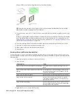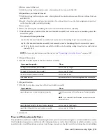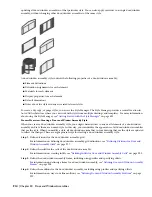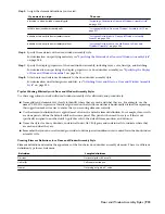
Then…
If you want to…
see
“
Adding Door and Window Assembly Element
Definitions as Display Components
” on page 950
.
add door/window assembly element definitions as display
components
see
“
Specifying the Layer, Color, and Linetype of a Door
and Window Assembly Style
” on page 951
.
specify layer, color and linetype settings for the display
components of a door/window assembly
see
“
Specifying the Hatching for Components of a Door
and Window Assembly Style
” on page 951
.
specify door/window assembly hatching
see
“
Adding Custom Graphics as a Display Component of
a Door and Window Assembly
” on page 952
.
add custom graphics as display components of a
door/window assembly style
see
“
Creating Cut Planes for a Door and Window
Assembly
” on page 953
.
create individual cut planes for door/window assembly styles
see
“
Specifying the Materials of a Door and Window
Assembly Style
” on page 948
.
specify the materials of the door/window assembly style
see
“
Attaching Notes and Files to a Door and Window
Assembly Style
” on page 953
.
add notes and files to the style
6
When you finish specifying the properties of the door/window assembly style, click OK.
7
If you want to assign the style to a door/window assembly tool, drag the style from the Style Manager to
a tool palette.
You can later rename the tool and specify other properties for it as described in “
Creating a Door and
Window Assembly Tool
” on page 912.
8
Click OK.
Defining Divisions for Door and Window Assembly Grids
The divisions of a grid define the orientation that determines the direction of the grid cells and mullions and they
define a division type that determines the number and size of cells.
NOTE Creating a nested grid is not a division rule. To create a nested grid, add a cell assignment. For more information, see
“
Creating a Nested Grid for a Door and Window Assembly
” on page 939
and
“
Working with Nested Grids in Door and
Window Assemblies
” on page 937
.
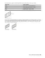
You can create a variety of division definitions under different names and then assign different divisions to each grid
in your door/window assembly. Although you can create multiple definitions, there can be only one division assignment
per grid. You create division definitions for a specific door/window assembly style and those definitions can be assigned
only to grids in door/window assemblies of that style. For more information about assigning divisions to a particular
grid, see “
Assigning a Division to a Door and Window Assembly Grid
” on page 936.
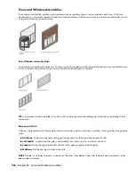
Division of Door and Window Assembly Grids
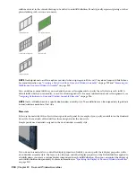
A door/window assembly consists of one or more grids, which are the framework for placing design elements in the
door/window assembly. The highest-level grid is the primary grid, which is also the outside edge of the door/window
assembly.
Door and Window Assembly Styles | 917
Summary of Contents for 00128-051462-9310 - AUTOCAD 2008 COMM UPG FRM 2005 DVD
Page 1: ...AutoCAD Architecture 2008 User s Guide 2007 ...
Page 4: ...1 2 3 4 5 6 7 8 9 10 ...
Page 40: ...xl Contents ...
Page 41: ...Workflow and User Interface 1 1 ...
Page 42: ...2 Chapter 1 Workflow and User Interface ...
Page 146: ...106 Chapter 3 Content Browser ...
Page 164: ...124 Chapter 4 Creating and Saving Drawings ...
Page 370: ...330 Chapter 6 Drawing Management ...
Page 440: ...400 Chapter 8 Drawing Compare ...
Page 528: ...488 Chapter 10 Display System ...
Page 540: ...500 Chapter 11 Style Manager ...
Page 612: ...572 Chapter 13 Content Creation Guidelines ...
Page 613: ...Conceptual Design 2 573 ...
Page 614: ...574 Chapter 14 Conceptual Design ...
Page 678: ...638 Chapter 16 ObjectViewer ...
Page 683: ...Designing with Architectural Objects 3 643 ...
Page 684: ...644 Chapter 18 Designing with Architectural Objects ...
Page 788: ...748 Chapter 18 Walls ...
Page 942: ...902 Chapter 19 Curtain Walls ...
Page 1042: ...1002 Chapter 21 AEC Polygons ...
Page 1052: ...Changing a door width 1012 Chapter 22 Doors ...
Page 1106: ...Changing a window width 1066 Chapter 23 Windows ...
Page 1172: ...1132 Chapter 24 Openings ...
Page 1226: ...Using grips to change the flight width of a spiral stair run 1186 Chapter 25 Stairs ...
Page 1368: ...Using the Angle grip to edit slab slope 1328 Chapter 28 Slabs and Roof Slabs ...
Page 1491: ...Design Utilities 4 1451 ...
Page 1492: ...1452 Chapter 30 Design Utilities ...
Page 1536: ...1496 Chapter 31 Layout Curves and Grids ...
Page 1564: ...1524 Chapter 32 Grids ...
Page 1611: ...Documentation 5 1571 ...
Page 1612: ...1572 Chapter 36 Documentation ...
Page 1706: ...Stretching a surface opening Moving a surface opening 1666 Chapter 36 Spaces ...
Page 1710: ...Offsetting the edge of a window opening on a freeform space surface 1670 Chapter 36 Spaces ...
Page 1956: ...1916 Chapter 42 Fields ...
Page 2035: ...Properties of a detail callout The Properties of a Callout Tool 1995 ...
Page 2060: ...2020 Chapter 45 Callouts ...
Page 2170: ...2130 Chapter 47 AEC Content and DesignCenter ...
Page 2171: ...Other Utilities 6 2131 ...
Page 2172: ...2132 Chapter 48 Other Utilities ...
Page 2182: ...2142 Chapter 51 Reference AEC Objects ...
Page 2212: ...2172 Chapter 52 Customizing and Adding New Content for Detail Components ...
Page 2217: ...AutoCAD Architecture 2008 Menus 54 2177 ...
Page 2226: ...2186 Chapter 54 AutoCAD Architecture 2008 Menus ...
Page 2268: ...2228 Index ...


