


The Basic Project Categories
For every building project in AutoCAD Architecture, the following basic category structure is displayed in the Project
Navigator:
■
<ProjectName>: This is the top node in the project, represented by a folder with the project name.
■
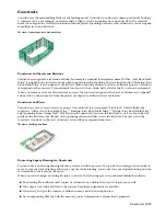
Constructs: This is the default folder for constructs in the project. When you create a construct, it is saved into
the Constructs category or one of its subcategories. For more information, see “
Constructs
” on page 217.
■
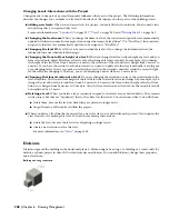
Elements: This is the default folder for elements in the project. When you create an element, it is saved into the
Elements category or one of its subcategories. For more information, see “
Elements
” on page 231.
■
Views: This is the default folder for view drawings in the project. When you create a view drawing, it is saved into
the Views category or one of its subcategories. For more information, see “
Views
” on page 242.
If you create model space views within a view drawing, they are placed under the view drawing in the same category
as the view drawing itself.
■
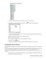
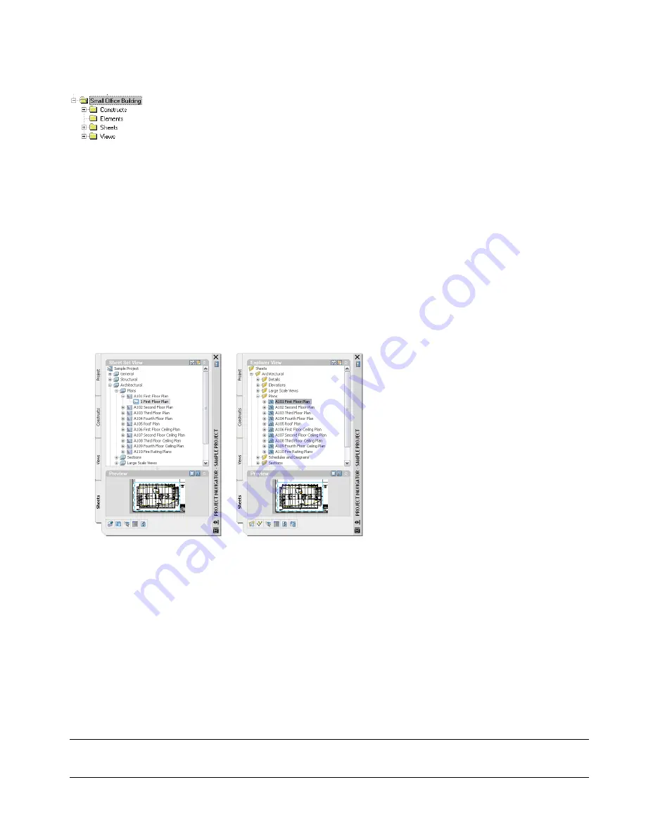
Sheets are arranged in two types of categories. In the Explorer view, sheet drawings are placed in folder categories.
When you create sheets or sheet views within a sheet drawing, they are placed in the same sheet drawing.
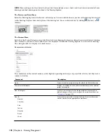
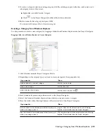
Sheet Set View tab on project (left) and Explorer View tab (right)
In the Sheet Set View tab, sheets are organized in sheet subsets. Sheet subsets are a logical structure rather than a
physical one. The sheet folder category does not need to be identical to the sheet subset in which the sheet is
placed. However, to avoid confusion, it is recommended that you have parallel structures in the sheet set and the
sheet categories. You can logically rearrange sheets into a different subset within the Sheet Set View tab, but that
will not change their physical location in the category or folder. Likewise, when you remove a sheet from a sheet
subset in the Sheet Set View, only the reference of the sheet to the subset is removed; the layout itself and its
containing sheet drawing are not deleted from the Sheets folder or subfolder. For more information, see “
Plotting
Sheets
” on page 262.
User-Defined Categories
Below the fixed main category structure, you can create subcategories and subcategory trees. Subcategories usually
represent components of your workflow. You might set up subcategories by discipline, by phase, by view type (working,
presentation, section, rendering, and so on), by sheet type (floor plan, ceiling plan, elevation, and so on), or by any
other system that you find helpful.
NOTE You cannot mix basic category types. For example, you cannot create a Construct subcategory within the Views
category or an Element subcategory within the Sheets category.
Categories | 211
Summary of Contents for 00128-051462-9310 - AUTOCAD 2008 COMM UPG FRM 2005 DVD
Page 1: ...AutoCAD Architecture 2008 User s Guide 2007 ...
Page 4: ...1 2 3 4 5 6 7 8 9 10 ...
Page 40: ...xl Contents ...
Page 41: ...Workflow and User Interface 1 1 ...
Page 42: ...2 Chapter 1 Workflow and User Interface ...
Page 146: ...106 Chapter 3 Content Browser ...
Page 164: ...124 Chapter 4 Creating and Saving Drawings ...
Page 370: ...330 Chapter 6 Drawing Management ...
Page 440: ...400 Chapter 8 Drawing Compare ...
Page 528: ...488 Chapter 10 Display System ...
Page 540: ...500 Chapter 11 Style Manager ...
Page 612: ...572 Chapter 13 Content Creation Guidelines ...
Page 613: ...Conceptual Design 2 573 ...
Page 614: ...574 Chapter 14 Conceptual Design ...
Page 678: ...638 Chapter 16 ObjectViewer ...
Page 683: ...Designing with Architectural Objects 3 643 ...
Page 684: ...644 Chapter 18 Designing with Architectural Objects ...
Page 788: ...748 Chapter 18 Walls ...
Page 942: ...902 Chapter 19 Curtain Walls ...
Page 1042: ...1002 Chapter 21 AEC Polygons ...
Page 1052: ...Changing a door width 1012 Chapter 22 Doors ...
Page 1106: ...Changing a window width 1066 Chapter 23 Windows ...
Page 1172: ...1132 Chapter 24 Openings ...
Page 1226: ...Using grips to change the flight width of a spiral stair run 1186 Chapter 25 Stairs ...
Page 1368: ...Using the Angle grip to edit slab slope 1328 Chapter 28 Slabs and Roof Slabs ...
Page 1491: ...Design Utilities 4 1451 ...
Page 1492: ...1452 Chapter 30 Design Utilities ...
Page 1536: ...1496 Chapter 31 Layout Curves and Grids ...
Page 1564: ...1524 Chapter 32 Grids ...
Page 1611: ...Documentation 5 1571 ...
Page 1612: ...1572 Chapter 36 Documentation ...
Page 1706: ...Stretching a surface opening Moving a surface opening 1666 Chapter 36 Spaces ...
Page 1710: ...Offsetting the edge of a window opening on a freeform space surface 1670 Chapter 36 Spaces ...
Page 1956: ...1916 Chapter 42 Fields ...
Page 2035: ...Properties of a detail callout The Properties of a Callout Tool 1995 ...
Page 2060: ...2020 Chapter 45 Callouts ...
Page 2170: ...2130 Chapter 47 AEC Content and DesignCenter ...
Page 2171: ...Other Utilities 6 2131 ...
Page 2172: ...2132 Chapter 48 Other Utilities ...
Page 2182: ...2142 Chapter 51 Reference AEC Objects ...
Page 2212: ...2172 Chapter 52 Customizing and Adding New Content for Detail Components ...
Page 2217: ...AutoCAD Architecture 2008 Menus 54 2177 ...
Page 2226: ...2186 Chapter 54 AutoCAD Architecture 2008 Menus ...
Page 2268: ...2228 Index ...


