


9
Under New Model Space View Name, enter a name for the new model space view containing the detail.
10
If necessary, select Generate Section/Elevation.
11
If you want to add a title mark to the new model space view, select Place Titlemark.
12
Select the scale for the model space view.
13
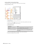
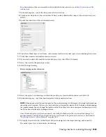
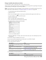
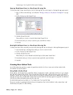
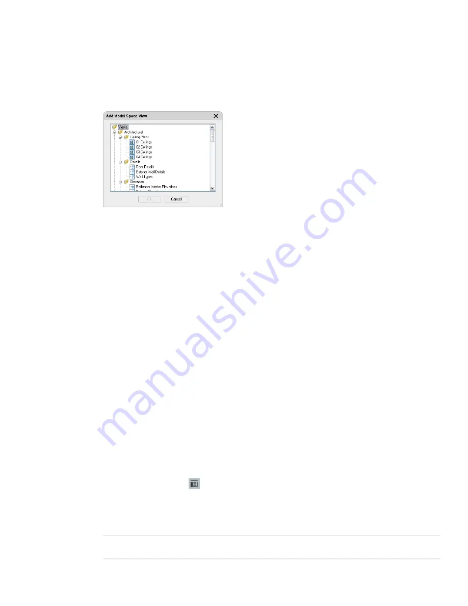
Click Existing Drawing.
Select a drawing to place the detail
14
Select the project view drawing in which to place the model space view, and click OK.
15
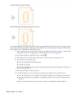
If you selected to create a detail with a section/elevation, specify the insertion point of the 2D
section/elevation result.
16
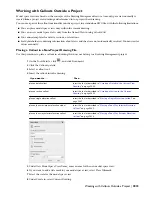
If you selected to create a detail without a section/elevation, specify the extents of the model space view
containing the area being detailed.
The extents of the model space view will dictate the default sheet view size, so if the model space boundary
is too small, you may have problems placing annotations in it.
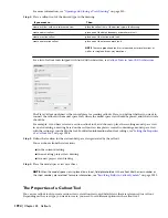
Once the model space view has been placed in the drawing, the field placeholders in the callout change
to a question mark. To resolve them, the model space view needs to be placed onto a sheet, as described
in “
Resolving Fields in Callout Symbols
” on page 2013.
17
To display the model space view in the Project Navigator, navigate to the target drawing, and expand it.
The model space view is listed under the drawing.
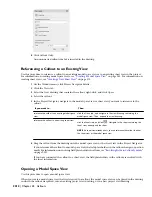
For information on opening the model space view, see “
Opening a Model Space View
” on page 2012.
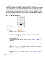
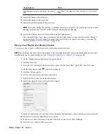
Creating a Detail in a New Drawing
Use this procedure to place a callout that creates a detail in a new project view drawing.
You can place each detail in its own detail drawing. The Detail View template set in the project is used to create the
new drawing. For more information, see “
Creating a New Project
” on page 174.
When you create a new drawing for a detail, it contains by default the same constructs, levels, and divisions as the
drawing from which the detail is taken. You can change that assignment, if necessary.
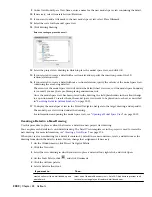
1
On the Window menu, click Project Navigator Palette.
2
Click the Views tab.
3
Select the view drawing in which you want to place a detail callout, right-click, and click Open.
4
On the Tools Palette, click
, and click Document.
5
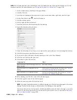
Click the Callouts palette.
6
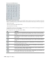
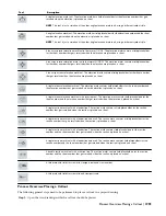
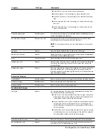
Select a detail callout tool:
Then…
If you want to…
select one of the detail boundary tools. AutoCAD Architecture provides tools
for circular, rectangular, and freeform detail boundaries.
create a callout with a detail boundary and
a detail mark
2002 | Chapter 45 Callouts
Summary of Contents for 00128-051462-9310 - AUTOCAD 2008 COMM UPG FRM 2005 DVD
Page 1: ...AutoCAD Architecture 2008 User s Guide 2007 ...
Page 4: ...1 2 3 4 5 6 7 8 9 10 ...
Page 40: ...xl Contents ...
Page 41: ...Workflow and User Interface 1 1 ...
Page 42: ...2 Chapter 1 Workflow and User Interface ...
Page 146: ...106 Chapter 3 Content Browser ...
Page 164: ...124 Chapter 4 Creating and Saving Drawings ...
Page 370: ...330 Chapter 6 Drawing Management ...
Page 440: ...400 Chapter 8 Drawing Compare ...
Page 528: ...488 Chapter 10 Display System ...
Page 540: ...500 Chapter 11 Style Manager ...
Page 612: ...572 Chapter 13 Content Creation Guidelines ...
Page 613: ...Conceptual Design 2 573 ...
Page 614: ...574 Chapter 14 Conceptual Design ...
Page 678: ...638 Chapter 16 ObjectViewer ...
Page 683: ...Designing with Architectural Objects 3 643 ...
Page 684: ...644 Chapter 18 Designing with Architectural Objects ...
Page 788: ...748 Chapter 18 Walls ...
Page 942: ...902 Chapter 19 Curtain Walls ...
Page 1042: ...1002 Chapter 21 AEC Polygons ...
Page 1052: ...Changing a door width 1012 Chapter 22 Doors ...
Page 1106: ...Changing a window width 1066 Chapter 23 Windows ...
Page 1172: ...1132 Chapter 24 Openings ...
Page 1226: ...Using grips to change the flight width of a spiral stair run 1186 Chapter 25 Stairs ...
Page 1368: ...Using the Angle grip to edit slab slope 1328 Chapter 28 Slabs and Roof Slabs ...
Page 1491: ...Design Utilities 4 1451 ...
Page 1492: ...1452 Chapter 30 Design Utilities ...
Page 1536: ...1496 Chapter 31 Layout Curves and Grids ...
Page 1564: ...1524 Chapter 32 Grids ...
Page 1611: ...Documentation 5 1571 ...
Page 1612: ...1572 Chapter 36 Documentation ...
Page 1706: ...Stretching a surface opening Moving a surface opening 1666 Chapter 36 Spaces ...
Page 1710: ...Offsetting the edge of a window opening on a freeform space surface 1670 Chapter 36 Spaces ...
Page 1956: ...1916 Chapter 42 Fields ...
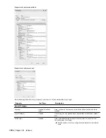
Page 2035: ...Properties of a detail callout The Properties of a Callout Tool 1995 ...
Page 2060: ...2020 Chapter 45 Callouts ...
Page 2170: ...2130 Chapter 47 AEC Content and DesignCenter ...
Page 2171: ...Other Utilities 6 2131 ...
Page 2172: ...2132 Chapter 48 Other Utilities ...
Page 2182: ...2142 Chapter 51 Reference AEC Objects ...
Page 2212: ...2172 Chapter 52 Customizing and Adding New Content for Detail Components ...
Page 2217: ...AutoCAD Architecture 2008 Menus 54 2177 ...
Page 2226: ...2186 Chapter 54 AutoCAD Architecture 2008 Menus ...
Page 2268: ...2228 Index ...


