


Once chosen, the template project is copied to the new location (selected in the Project Browser window before clicking
the New Project icon) and then automatically re-pathed. A template project provides the equivalent benefits that DWT
files provide for individual drawing files. Template projects help to speed project setup and ensure office standards and
consistency.
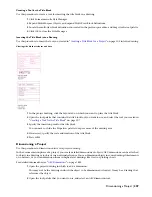
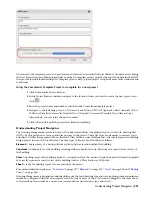
Using the Commercial Template Project as template for a new project
1
Click File menu
➤
Project Browser.
2
In the Project Browser window, navigate to the location where you want to create the new project, and
click
.
3
Enter the project name and number, and then click Create from template project.
4
Navigate to the following project: C:\Documents and Settings\All Users\Application Data\Autodesk\ACD-A
2008\enu\Template\Commercial Template Project (Imperial)\Commercial Template Project (Imperial).apj.
Alternatively, you can select the metric version.
5
Click OK and wait until the project has finished repathing.
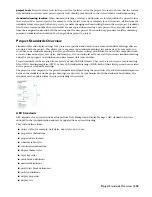
Understanding Project Navigator
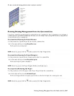
The Drawing Management system in AutoCAD Architecture includes four different types of AutoCAD drawing files
(DWG). Each is designed to serve a particular purpose in the project. These file types are elements, constructs, views
and sheets. All files are organized into a collection of files within a series of folders that collectively represent a building
design project in AutoCAD Architecture. The four types of files are briefly defined as follows:
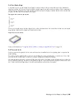
Element
A discreet piece of a design without explicit physical location within the building.
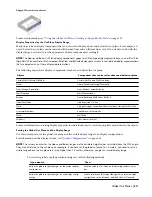
Construct
A unique piece of the building occurring within a particular zone (Division) on a specific floor (Level) of
the building.
View
A working report of the building model. A view gathers all of the constructs (and their nested elements) required
to correctly represent a specific view of the building (such as a Plan, Section or 3D Model).
Sheet
A ready for printing report of some portion of the project.
For a more detailed description, see “
Constructs
” on page 217, “
Elements
” on page 231, “
Views
” on page 242, and “
Plotting
Sheets
” on page 262.
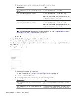
Drawing Management is designed around the philosophy that each drawing type and scale requiring unique annotations
should be configured within its own separate view file. One or more of these views can be dragged to the same sheet,
so there will not necessarily be a one-to-one correspondence between the views and sheets.
Understanding Project Navigator | 321
Summary of Contents for 00128-051462-9310 - AUTOCAD 2008 COMM UPG FRM 2005 DVD
Page 1: ...AutoCAD Architecture 2008 User s Guide 2007 ...
Page 4: ...1 2 3 4 5 6 7 8 9 10 ...
Page 40: ...xl Contents ...
Page 41: ...Workflow and User Interface 1 1 ...
Page 42: ...2 Chapter 1 Workflow and User Interface ...
Page 146: ...106 Chapter 3 Content Browser ...
Page 164: ...124 Chapter 4 Creating and Saving Drawings ...
Page 370: ...330 Chapter 6 Drawing Management ...
Page 440: ...400 Chapter 8 Drawing Compare ...
Page 528: ...488 Chapter 10 Display System ...
Page 540: ...500 Chapter 11 Style Manager ...
Page 612: ...572 Chapter 13 Content Creation Guidelines ...
Page 613: ...Conceptual Design 2 573 ...
Page 614: ...574 Chapter 14 Conceptual Design ...
Page 678: ...638 Chapter 16 ObjectViewer ...
Page 683: ...Designing with Architectural Objects 3 643 ...
Page 684: ...644 Chapter 18 Designing with Architectural Objects ...
Page 788: ...748 Chapter 18 Walls ...
Page 942: ...902 Chapter 19 Curtain Walls ...
Page 1042: ...1002 Chapter 21 AEC Polygons ...
Page 1052: ...Changing a door width 1012 Chapter 22 Doors ...
Page 1106: ...Changing a window width 1066 Chapter 23 Windows ...
Page 1172: ...1132 Chapter 24 Openings ...
Page 1226: ...Using grips to change the flight width of a spiral stair run 1186 Chapter 25 Stairs ...
Page 1368: ...Using the Angle grip to edit slab slope 1328 Chapter 28 Slabs and Roof Slabs ...
Page 1491: ...Design Utilities 4 1451 ...
Page 1492: ...1452 Chapter 30 Design Utilities ...
Page 1536: ...1496 Chapter 31 Layout Curves and Grids ...
Page 1564: ...1524 Chapter 32 Grids ...
Page 1611: ...Documentation 5 1571 ...
Page 1612: ...1572 Chapter 36 Documentation ...
Page 1706: ...Stretching a surface opening Moving a surface opening 1666 Chapter 36 Spaces ...
Page 1710: ...Offsetting the edge of a window opening on a freeform space surface 1670 Chapter 36 Spaces ...
Page 1956: ...1916 Chapter 42 Fields ...
Page 2035: ...Properties of a detail callout The Properties of a Callout Tool 1995 ...
Page 2060: ...2020 Chapter 45 Callouts ...
Page 2170: ...2130 Chapter 47 AEC Content and DesignCenter ...
Page 2171: ...Other Utilities 6 2131 ...
Page 2172: ...2132 Chapter 48 Other Utilities ...
Page 2182: ...2142 Chapter 51 Reference AEC Objects ...
Page 2212: ...2172 Chapter 52 Customizing and Adding New Content for Detail Components ...
Page 2217: ...AutoCAD Architecture 2008 Menus 54 2177 ...
Page 2226: ...2186 Chapter 54 AutoCAD Architecture 2008 Menus ...
Page 2268: ...2228 Index ...


