


1
Select the elevation to be changed, right-click, and click Linework
➤
Edit.
2
Select the lines that you want to assign to a display component, right-click, and click Modify Component.
A list of available display components is displayed.
3
Select the component you want to put the lines on.
For example, if you want to make the lines invisible, select Erased Vectors for Linework Component.
You can also click
(Match existing linework), and select linework in the elevation whose display
component you want to match.
4
Click OK.
5
To finish the linework editing process, select any line in the elevation, right-click, and select Edit in
Place
➤
Save Changes to save the changes you made, or click Edit in Place
➤
Discard Changes to undo
your linework changes.
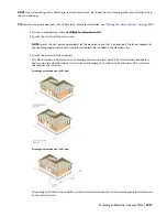
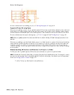
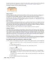
Merging Linework into a 2D Elevation
Use this procedure to merge geometry into a 2D elevation. When you merge linework into an elevation, you assign
additional linework to a display component of an elevation. Use this feature when you want to add detail, or add
linework that you did not model.
1
Draw the geometry that you want to merge into a 2D elevation.
2
Select the 2D elevation to be changed, right-click, and click Linework
➤
Merge.
3
Select the geometry to merge into the elevation, and press
ENTER
.
4
Select the display component to which you want to assign the linework.
You can also click
(Match existing linework) and select linework in the elevation whose display
component you want to match.
5
Click OK.
The linework is merged into the 2D elevation. When you select the elevation, the linework is selected with
it.
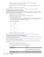
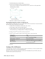
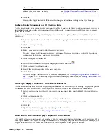
Changing the Location of a 2D or 3D Elevation
You can relocate an elevation by changing the coordinate values of its insertion point. The elevation also has an
orientation with respect to the WCS or the current UCS. For example, if the top and bottom of the elevation are parallel
to the XY plane, its normal is parallel to the Z axis. You can change the orientation of the elevation by aligning its
normal with another axis. You can also rotate the elevation on its plane by changing the rotation angle.
For information about the world coordinate system (WCS) and the user coordinate system (UCS), see “Use World and
User Coordinate Systems in 3D” in AutoCAD Help.
1
Double-click the elevation you want to move.
2
On the Properties palette, expand Basic, and expand Location.
3
Click Additional Information.
4
Specify a new location or rotation:
Then…
If you want to…
enter new coordinate values under Insertion Point.
relocate the elevation
make the normal of the elevation parallel to the Z axis: under
Normal, enter 1 for Z, and enter 0 for X and Y.
locate the elevation on the XY plane
make the normal of the elevation parallel to the X axis: under
Normal, enter 1 for X, and enter 0 for Y and Z.
locate the elevation on the YZ plane
Changing the Location of a 2D or 3D Elevation | 1827
Summary of Contents for 00128-051462-9310 - AUTOCAD 2008 COMM UPG FRM 2005 DVD
Page 1: ...AutoCAD Architecture 2008 User s Guide 2007 ...
Page 4: ...1 2 3 4 5 6 7 8 9 10 ...
Page 40: ...xl Contents ...
Page 41: ...Workflow and User Interface 1 1 ...
Page 42: ...2 Chapter 1 Workflow and User Interface ...
Page 146: ...106 Chapter 3 Content Browser ...
Page 164: ...124 Chapter 4 Creating and Saving Drawings ...
Page 370: ...330 Chapter 6 Drawing Management ...
Page 440: ...400 Chapter 8 Drawing Compare ...
Page 528: ...488 Chapter 10 Display System ...
Page 540: ...500 Chapter 11 Style Manager ...
Page 612: ...572 Chapter 13 Content Creation Guidelines ...
Page 613: ...Conceptual Design 2 573 ...
Page 614: ...574 Chapter 14 Conceptual Design ...
Page 678: ...638 Chapter 16 ObjectViewer ...
Page 683: ...Designing with Architectural Objects 3 643 ...
Page 684: ...644 Chapter 18 Designing with Architectural Objects ...
Page 788: ...748 Chapter 18 Walls ...
Page 942: ...902 Chapter 19 Curtain Walls ...
Page 1042: ...1002 Chapter 21 AEC Polygons ...
Page 1052: ...Changing a door width 1012 Chapter 22 Doors ...
Page 1106: ...Changing a window width 1066 Chapter 23 Windows ...
Page 1172: ...1132 Chapter 24 Openings ...
Page 1226: ...Using grips to change the flight width of a spiral stair run 1186 Chapter 25 Stairs ...
Page 1368: ...Using the Angle grip to edit slab slope 1328 Chapter 28 Slabs and Roof Slabs ...
Page 1491: ...Design Utilities 4 1451 ...
Page 1492: ...1452 Chapter 30 Design Utilities ...
Page 1536: ...1496 Chapter 31 Layout Curves and Grids ...
Page 1564: ...1524 Chapter 32 Grids ...
Page 1611: ...Documentation 5 1571 ...
Page 1612: ...1572 Chapter 36 Documentation ...
Page 1706: ...Stretching a surface opening Moving a surface opening 1666 Chapter 36 Spaces ...
Page 1710: ...Offsetting the edge of a window opening on a freeform space surface 1670 Chapter 36 Spaces ...
Page 1956: ...1916 Chapter 42 Fields ...
Page 2035: ...Properties of a detail callout The Properties of a Callout Tool 1995 ...
Page 2060: ...2020 Chapter 45 Callouts ...
Page 2170: ...2130 Chapter 47 AEC Content and DesignCenter ...
Page 2171: ...Other Utilities 6 2131 ...
Page 2172: ...2132 Chapter 48 Other Utilities ...
Page 2182: ...2142 Chapter 51 Reference AEC Objects ...
Page 2212: ...2172 Chapter 52 Customizing and Adding New Content for Detail Components ...
Page 2217: ...AutoCAD Architecture 2008 Menus 54 2177 ...
Page 2226: ...2186 Chapter 54 AutoCAD Architecture 2008 Menus ...
Page 2268: ...2228 Index ...


