


Multi-View Blocks
A multi-view block is an AutoCAD Architecture object that can have different representations in different view directions.
You create a multi-view block from AutoCAD blocks that represent the different views of the custom object that you
are creating.
Understanding Multi-View Blocks
Multi-view blocks can represent different types of objects in AutoCAD Architecture. They are typically used to represent
the following items:
■
Furniture and fixtures, such as tables and kitchen sinks
■
Annotation components, such as revision clouds or fire rating signs
■
Schedule tags, such as door numbers
Multi-view blocks can be displayed differently in each view direction and each display representation. For example,
the top view of a multi-view block representing a kitchen sink shows the top of the sink; the bottom view shows the
bottom of the sink; and there are representations for left, right, front, and back views. Additionally, you can define a
different group of displays for each display representation, so that you can have one set of views for Plan view and
another for Reflected view.
You can use a multi-view block as a cutout in objects such as walls, slabs, and curtain walls. You create a view block to
represent the cutting body. The block forms the body that will be subtracted from objects by applying the multi-view
block as interference. For example, you can create a skylight as a multi-view block and specify the block as a subtractive
Boolean in a slab.
Predefined Multi-View Blocks
The content folders of AutoCAD Architecture contain predefined multi-view blocks for various design purposes, such
as furniture, electrical appliances, annotation symbols, schedule tags, and other useful elements. You can access these
multi-view blocks from DesignCenter
™
. For more information, see “
AEC Content and DesignCenter
” on page 2115.
Creating Multi-View Block Definitions
Each multi-view block in a drawing is based on a definition that specifies the display representations in which the block
can be viewed, as well as the views available in each representation. From a multi-view block definition, you can create
as many multi-view blocks as you need.
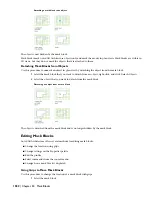
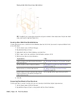
Multi-view blocks typically represent 3D architectural objects. For example, you can create customized cabinetry by
drawing plan, elevation, and model views, and saving each view as an individual AutoCAD block. You assign each
block to a view when you create the multi-view block definition. The blocks (top, bottom, front, back, left, right, and
model views) are used to define the custom object as a single multi-view block. Prior to defining the block, you can
add points on the Defpoints layer to identify additional insertion points for the view block. You set the display
representations and view directions in the process of defining the multi-view block.
You can see the individual blocks of your custom object as one assembly in plan, elevation, and isometric views after
inserting them in the drawing as a multi-view block. For more information about working with blocks, see “Overview
of Blocks” in AutoCAD Help. For more information about display representations, see “
Display Representations
” on
page 451.
TIP The quickest way to locate and view an AutoCAD topic referenced in AutoCAD Architecture Help is to click the Search
tab in the Help window, select the Search titles only option, and then copy and paste or type in the AutoCAD topic name,
and click List Topics.
1558 | Chapter 35 Multi-View Blocks
Summary of Contents for 00128-051462-9310 - AUTOCAD 2008 COMM UPG FRM 2005 DVD
Page 1: ...AutoCAD Architecture 2008 User s Guide 2007 ...
Page 4: ...1 2 3 4 5 6 7 8 9 10 ...
Page 40: ...xl Contents ...
Page 41: ...Workflow and User Interface 1 1 ...
Page 42: ...2 Chapter 1 Workflow and User Interface ...
Page 146: ...106 Chapter 3 Content Browser ...
Page 164: ...124 Chapter 4 Creating and Saving Drawings ...
Page 370: ...330 Chapter 6 Drawing Management ...
Page 440: ...400 Chapter 8 Drawing Compare ...
Page 528: ...488 Chapter 10 Display System ...
Page 540: ...500 Chapter 11 Style Manager ...
Page 612: ...572 Chapter 13 Content Creation Guidelines ...
Page 613: ...Conceptual Design 2 573 ...
Page 614: ...574 Chapter 14 Conceptual Design ...
Page 678: ...638 Chapter 16 ObjectViewer ...
Page 683: ...Designing with Architectural Objects 3 643 ...
Page 684: ...644 Chapter 18 Designing with Architectural Objects ...
Page 788: ...748 Chapter 18 Walls ...
Page 942: ...902 Chapter 19 Curtain Walls ...
Page 1042: ...1002 Chapter 21 AEC Polygons ...
Page 1052: ...Changing a door width 1012 Chapter 22 Doors ...
Page 1106: ...Changing a window width 1066 Chapter 23 Windows ...
Page 1172: ...1132 Chapter 24 Openings ...
Page 1226: ...Using grips to change the flight width of a spiral stair run 1186 Chapter 25 Stairs ...
Page 1368: ...Using the Angle grip to edit slab slope 1328 Chapter 28 Slabs and Roof Slabs ...
Page 1491: ...Design Utilities 4 1451 ...
Page 1492: ...1452 Chapter 30 Design Utilities ...
Page 1536: ...1496 Chapter 31 Layout Curves and Grids ...
Page 1564: ...1524 Chapter 32 Grids ...
Page 1611: ...Documentation 5 1571 ...
Page 1612: ...1572 Chapter 36 Documentation ...
Page 1706: ...Stretching a surface opening Moving a surface opening 1666 Chapter 36 Spaces ...
Page 1710: ...Offsetting the edge of a window opening on a freeform space surface 1670 Chapter 36 Spaces ...
Page 1956: ...1916 Chapter 42 Fields ...
Page 2035: ...Properties of a detail callout The Properties of a Callout Tool 1995 ...
Page 2060: ...2020 Chapter 45 Callouts ...
Page 2170: ...2130 Chapter 47 AEC Content and DesignCenter ...
Page 2171: ...Other Utilities 6 2131 ...
Page 2172: ...2132 Chapter 48 Other Utilities ...
Page 2182: ...2142 Chapter 51 Reference AEC Objects ...
Page 2212: ...2172 Chapter 52 Customizing and Adding New Content for Detail Components ...
Page 2217: ...AutoCAD Architecture 2008 Menus 54 2177 ...
Page 2226: ...2186 Chapter 54 AutoCAD Architecture 2008 Menus ...
Page 2268: ...2228 Index ...


