


5
In the left pane, select Mullions under Element Definitions.
6
Click New Mullion.
7
Enter a descriptive name for the mullion.
8
Specify a width and depth for the mullion.
9
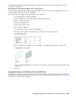
Specify the offsets you want.
For more information, see “
Specifying Offsets for the Mullions of a Curtain Wall Unit
” on page 862.
10
Click OK.
After you create a mullion definition, you can assign it to any mullion in a curtain wall unit. For more information,
see “
Assigning Definitions to the Mullions of a Curtain Wall Unit
” on page 871.
Creating a Profile for Curtain Wall Unit Mullions
Use this procedure to create a profile that you can use to define the shape of a curtain wall unit mullion definition.
You can then extrude the profile to create mullions from it.
The height and the width of the polyline you use to create the profile define the default height and width of the curtain
wall unit mullion. The insertion point of the profile is aligned with the centroid of the mullion.
1
Draw a closed polyline of the height and the depth needed for the resulting curtain wall unit mullion.
2
Select the polyline, right-click, and click Convert to
➤
Profile Definition.
3
Enter
c
(Centroid) for the insertion point of the profile.
The insertion point of the profile is aligned with the centroid of the mullion.
4
Enter a name for the profile, and click OK.
You can now use the profile as a curtain wall unit mullion. For more information, see “
Defining the Mullions
of a Curtain Wall Unit Using a Profile
” on page 861.
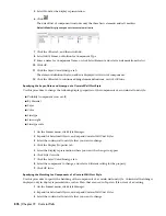
Defining the Mullions of a Curtain Wall Unit Using a Profile
Use this procedure to create a mullion element definition from a profile. If you do not want a straight edge to your
mullions, you can use a profile to define mullions with curves, jags, or any other shape.
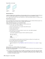
NOTE The insertion point of the profile is aligned with the centroid of the mullion.
Infill alignments with default and profile-based mullions
1
Create the profile to use for the mullion.
For information, see “
Creating a Profile for Curtain Wall Unit Mullions
” on page 861.
2
On the Format menu, click Style Manager.
3
Expand Architectural Objects, and expand Curtain Wall Unit Styles.
4
Select a curtain wall unit style.
5
Click the Design Rules tab.
6
In the left pane, select Mullions under Element Definitions.
7
Click the New Mullion icon to create a new mullion definition.
Defining Curtain Wall Unit Mullions | 861
Summary of Contents for 00128-051462-9310 - AUTOCAD 2008 COMM UPG FRM 2005 DVD
Page 1: ...AutoCAD Architecture 2008 User s Guide 2007 ...
Page 4: ...1 2 3 4 5 6 7 8 9 10 ...
Page 40: ...xl Contents ...
Page 41: ...Workflow and User Interface 1 1 ...
Page 42: ...2 Chapter 1 Workflow and User Interface ...
Page 146: ...106 Chapter 3 Content Browser ...
Page 164: ...124 Chapter 4 Creating and Saving Drawings ...
Page 370: ...330 Chapter 6 Drawing Management ...
Page 440: ...400 Chapter 8 Drawing Compare ...
Page 528: ...488 Chapter 10 Display System ...
Page 540: ...500 Chapter 11 Style Manager ...
Page 612: ...572 Chapter 13 Content Creation Guidelines ...
Page 613: ...Conceptual Design 2 573 ...
Page 614: ...574 Chapter 14 Conceptual Design ...
Page 678: ...638 Chapter 16 ObjectViewer ...
Page 683: ...Designing with Architectural Objects 3 643 ...
Page 684: ...644 Chapter 18 Designing with Architectural Objects ...
Page 788: ...748 Chapter 18 Walls ...
Page 942: ...902 Chapter 19 Curtain Walls ...
Page 1042: ...1002 Chapter 21 AEC Polygons ...
Page 1052: ...Changing a door width 1012 Chapter 22 Doors ...
Page 1106: ...Changing a window width 1066 Chapter 23 Windows ...
Page 1172: ...1132 Chapter 24 Openings ...
Page 1226: ...Using grips to change the flight width of a spiral stair run 1186 Chapter 25 Stairs ...
Page 1368: ...Using the Angle grip to edit slab slope 1328 Chapter 28 Slabs and Roof Slabs ...
Page 1491: ...Design Utilities 4 1451 ...
Page 1492: ...1452 Chapter 30 Design Utilities ...
Page 1536: ...1496 Chapter 31 Layout Curves and Grids ...
Page 1564: ...1524 Chapter 32 Grids ...
Page 1611: ...Documentation 5 1571 ...
Page 1612: ...1572 Chapter 36 Documentation ...
Page 1706: ...Stretching a surface opening Moving a surface opening 1666 Chapter 36 Spaces ...
Page 1710: ...Offsetting the edge of a window opening on a freeform space surface 1670 Chapter 36 Spaces ...
Page 1956: ...1916 Chapter 42 Fields ...
Page 2035: ...Properties of a detail callout The Properties of a Callout Tool 1995 ...
Page 2060: ...2020 Chapter 45 Callouts ...
Page 2170: ...2130 Chapter 47 AEC Content and DesignCenter ...
Page 2171: ...Other Utilities 6 2131 ...
Page 2172: ...2132 Chapter 48 Other Utilities ...
Page 2182: ...2142 Chapter 51 Reference AEC Objects ...
Page 2212: ...2172 Chapter 52 Customizing and Adding New Content for Detail Components ...
Page 2217: ...AutoCAD Architecture 2008 Menus 54 2177 ...
Page 2226: ...2186 Chapter 54 AutoCAD Architecture 2008 Menus ...
Page 2268: ...2228 Index ...


