


Viewing the Connection Between Tags and Objects
Use this procedure to view the current link between a schedule tag and an object. If you have many tags and are not
sure how they are attached, it is useful to see this link displayed. This procedure turns on the General display
representation for Anchor Tag To Entity and Anchor Extended Tag to Entity in the current view.
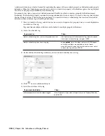
1
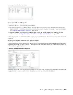
On the Format menu, click the Display Manager.
2
Expand Sets.
3
Select the current display set, which appears in bold in the list under Sets.
4
Click the Display Representation Control tab.
5
In the Objects list, locate Anchor Tag To Entity and Anchor Extended Tag to Entity, and select the General
display representation for both.
6
Click OK.
7
Regenerate the drawing, if necessary.
The link between the schedule tag and the object is displayed as an arc. The tag and object are attached
from insertion point to insertion point.
Renumbering Property Set Data
Use this procedure to renumber objects that are included in a schedule or linked to schedule tags. You may want to do
this if you moved them in the building model or if you have deleted objects. Only those property definitions with a
Type of Auto Increment—Integer or Auto Increment—Character can be renumbered with this procedure. For more
information, see “
Adding Tags Using Schedule Tag Tools
” on page 2030.
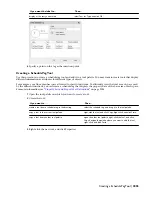
1
Open the tool palette that you want to use, and select the Renumber Data tool.
A Renumber Data tool is located with the Scheduling and Reporting Tools in the Stock Tool Catalog. You
can add this tool to any tool palette. For more information, see “
Content Browser
” on page 79.
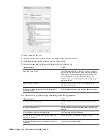
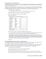
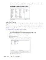
2
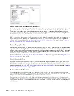
In the Data Renumber dialog, select the property set to renumber.
You select the property set that contains the number property. For example, if you renumber doors, you
select the DoorObjects property set.
3
Select the start number.
4
Select an increment value.
Each number in the drawing is increased by this amount in the drawing when the property set data is
renumbered. For example, if the start number is 1 and the increment is 3, the sequence would number 1,
4, 7, 10, and so on.
5
Select Attach New Property Set to add a new property set to the numbering sequence.
6
Click OK.
7
Select the object or schedule tag to which you want to assign the new start number, continue renumbering,
and press
ENTER
.
NOTE Under certain circumstances, such as after Renumber Data during RefEdit, you may see duplicate property set definition
names. For example, the property set definition name may be preceded by “$1$.” Modify these property set definitions by
opening the attached drawing and making the changes. For more information, see “Edit Selected Objects in Referenced
Drawings and Blocks” in AutoCAD Help.
2038 | Chapter 46 Schedules and Display Themes
Summary of Contents for 00128-051462-9310 - AUTOCAD 2008 COMM UPG FRM 2005 DVD
Page 1: ...AutoCAD Architecture 2008 User s Guide 2007 ...
Page 4: ...1 2 3 4 5 6 7 8 9 10 ...
Page 40: ...xl Contents ...
Page 41: ...Workflow and User Interface 1 1 ...
Page 42: ...2 Chapter 1 Workflow and User Interface ...
Page 146: ...106 Chapter 3 Content Browser ...
Page 164: ...124 Chapter 4 Creating and Saving Drawings ...
Page 370: ...330 Chapter 6 Drawing Management ...
Page 440: ...400 Chapter 8 Drawing Compare ...
Page 528: ...488 Chapter 10 Display System ...
Page 540: ...500 Chapter 11 Style Manager ...
Page 612: ...572 Chapter 13 Content Creation Guidelines ...
Page 613: ...Conceptual Design 2 573 ...
Page 614: ...574 Chapter 14 Conceptual Design ...
Page 678: ...638 Chapter 16 ObjectViewer ...
Page 683: ...Designing with Architectural Objects 3 643 ...
Page 684: ...644 Chapter 18 Designing with Architectural Objects ...
Page 788: ...748 Chapter 18 Walls ...
Page 942: ...902 Chapter 19 Curtain Walls ...
Page 1042: ...1002 Chapter 21 AEC Polygons ...
Page 1052: ...Changing a door width 1012 Chapter 22 Doors ...
Page 1106: ...Changing a window width 1066 Chapter 23 Windows ...
Page 1172: ...1132 Chapter 24 Openings ...
Page 1226: ...Using grips to change the flight width of a spiral stair run 1186 Chapter 25 Stairs ...
Page 1368: ...Using the Angle grip to edit slab slope 1328 Chapter 28 Slabs and Roof Slabs ...
Page 1491: ...Design Utilities 4 1451 ...
Page 1492: ...1452 Chapter 30 Design Utilities ...
Page 1536: ...1496 Chapter 31 Layout Curves and Grids ...
Page 1564: ...1524 Chapter 32 Grids ...
Page 1611: ...Documentation 5 1571 ...
Page 1612: ...1572 Chapter 36 Documentation ...
Page 1706: ...Stretching a surface opening Moving a surface opening 1666 Chapter 36 Spaces ...
Page 1710: ...Offsetting the edge of a window opening on a freeform space surface 1670 Chapter 36 Spaces ...
Page 1956: ...1916 Chapter 42 Fields ...
Page 2035: ...Properties of a detail callout The Properties of a Callout Tool 1995 ...
Page 2060: ...2020 Chapter 45 Callouts ...
Page 2170: ...2130 Chapter 47 AEC Content and DesignCenter ...
Page 2171: ...Other Utilities 6 2131 ...
Page 2172: ...2132 Chapter 48 Other Utilities ...
Page 2182: ...2142 Chapter 51 Reference AEC Objects ...
Page 2212: ...2172 Chapter 52 Customizing and Adding New Content for Detail Components ...
Page 2217: ...AutoCAD Architecture 2008 Menus 54 2177 ...
Page 2226: ...2186 Chapter 54 AutoCAD Architecture 2008 Menus ...
Page 2268: ...2228 Index ...


