


can add a mask block to a drawing if the drawing contains a mask block definition. For more information, see “
Creating
Mask Block Definitions
” on page 1544.
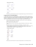
TIP When you add mask blocks to your drawing, insert them on a separate layer. You can turn the layer off in 3D views,
where the mask blocks no longer mask any objects.
1
If a mask block does not already exist in the current drawing, then create or import a mask block definition.
For more information, see “
Importing Mask Block Definitions
” on page 1545.
2
Open the tool palette that you want to use, and select a mask block tool.
A mask block tool is located on the Drafting tool palette and in the Drafting Tools category in the AutoCAD
Architecture Stock Tool catalog. You can add this tool to any tool palette. For more information, see
“
Understanding the Content Browser
” on page 80.
3
Specify the insertion point of the mask block.
You can move or hide the Properties palette to expose more of the drawing area.
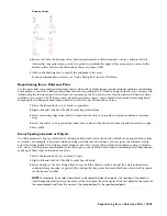
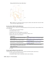
NOTE If you are using a mask block to mask a wall, the mask block must be located at the baseline of the wall
(Z = 0). Even though the wall components are at different heights, the plan display representation draws them
at the height of the baseline, as they would be drawn on paper.
4
Continue adding mask blocks, and press
ENTER
.
The mask blocks are displayed in the drawing at the insertion point you specified. To use a mask block to
clean up or correct an object in the drawing, attach the object to the mask block.
Adding a Mask Block with User-Specified Settings
Use this procedure to add a mask block with settings that you specify.
1
Open the tool palette that contains the mask block tool you want to use, and select the tool.
(You may have to scroll to display the desired tool.)
2
On the Properties palette, expand Basic, and expand General.
3
Select a definition.
4
Expand Scale.
5
Enter the X, Y, and Z scale of the mask block. The X, Y, and Z scales represent the distance from the insertion
point.
6
Alternately, expand Location, and select Yes for Specify scale on screen. Use your pointing device to
designate the scale of the mask block.
7
In the drawing area, specify the insertion point of the mask block.
You can move or hide the Properties palette to expose more of the drawing area.
8
Continue adding mask blocks, and press
ENTER
.
To use a mask block to clean up or correct an object in the drawing, attach the object to the mask block.
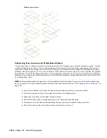
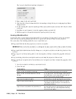
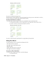
Creating a Mask Block from Polylines
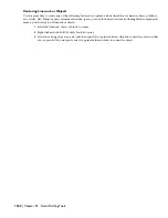
Use this procedure to create a mask block reference from one or more closed polylines. If you use more than one polyline
to create your mask block, the polylines must be completely within or completely outside each other; they cannot
overlap or touch. Polylines that are within each other can be specified as void areas that become holes when the mask
block is created.
1
Select the polylines, right-click, and click Convert To
➤
Mask Block.
Adding a Mask Block with User-Specified Settings | 1549
Summary of Contents for 00128-051462-9310 - AUTOCAD 2008 COMM UPG FRM 2005 DVD
Page 1: ...AutoCAD Architecture 2008 User s Guide 2007 ...
Page 4: ...1 2 3 4 5 6 7 8 9 10 ...
Page 40: ...xl Contents ...
Page 41: ...Workflow and User Interface 1 1 ...
Page 42: ...2 Chapter 1 Workflow and User Interface ...
Page 146: ...106 Chapter 3 Content Browser ...
Page 164: ...124 Chapter 4 Creating and Saving Drawings ...
Page 370: ...330 Chapter 6 Drawing Management ...
Page 440: ...400 Chapter 8 Drawing Compare ...
Page 528: ...488 Chapter 10 Display System ...
Page 540: ...500 Chapter 11 Style Manager ...
Page 612: ...572 Chapter 13 Content Creation Guidelines ...
Page 613: ...Conceptual Design 2 573 ...
Page 614: ...574 Chapter 14 Conceptual Design ...
Page 678: ...638 Chapter 16 ObjectViewer ...
Page 683: ...Designing with Architectural Objects 3 643 ...
Page 684: ...644 Chapter 18 Designing with Architectural Objects ...
Page 788: ...748 Chapter 18 Walls ...
Page 942: ...902 Chapter 19 Curtain Walls ...
Page 1042: ...1002 Chapter 21 AEC Polygons ...
Page 1052: ...Changing a door width 1012 Chapter 22 Doors ...
Page 1106: ...Changing a window width 1066 Chapter 23 Windows ...
Page 1172: ...1132 Chapter 24 Openings ...
Page 1226: ...Using grips to change the flight width of a spiral stair run 1186 Chapter 25 Stairs ...
Page 1368: ...Using the Angle grip to edit slab slope 1328 Chapter 28 Slabs and Roof Slabs ...
Page 1491: ...Design Utilities 4 1451 ...
Page 1492: ...1452 Chapter 30 Design Utilities ...
Page 1536: ...1496 Chapter 31 Layout Curves and Grids ...
Page 1564: ...1524 Chapter 32 Grids ...
Page 1611: ...Documentation 5 1571 ...
Page 1612: ...1572 Chapter 36 Documentation ...
Page 1706: ...Stretching a surface opening Moving a surface opening 1666 Chapter 36 Spaces ...
Page 1710: ...Offsetting the edge of a window opening on a freeform space surface 1670 Chapter 36 Spaces ...
Page 1956: ...1916 Chapter 42 Fields ...
Page 2035: ...Properties of a detail callout The Properties of a Callout Tool 1995 ...
Page 2060: ...2020 Chapter 45 Callouts ...
Page 2170: ...2130 Chapter 47 AEC Content and DesignCenter ...
Page 2171: ...Other Utilities 6 2131 ...
Page 2172: ...2132 Chapter 48 Other Utilities ...
Page 2182: ...2142 Chapter 51 Reference AEC Objects ...
Page 2212: ...2172 Chapter 52 Customizing and Adding New Content for Detail Components ...
Page 2217: ...AutoCAD Architecture 2008 Menus 54 2177 ...
Page 2226: ...2186 Chapter 54 AutoCAD Architecture 2008 Menus ...
Page 2268: ...2228 Index ...


