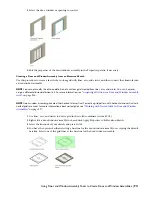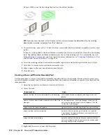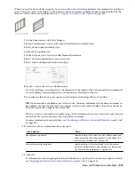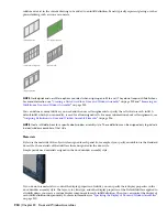
Creating a Panel Infill for a Door and Window Assembly
Use this procedure to create a simple panel infill to represent basic cladding materials in the door/window assembly,
such as a stone wall panel, concrete panel, metal panel, or glazing infill.
Because door/window assemblies can contain multiple infills, it is helpful to use a naming convention for panel infills
that indicates the infill location or purpose within the door/window assembly. For example, L3-FL1- Stone Panel
identifies a stone panel in a third-level grid on Floor 1.
1
On the Format menu, click Style Manager.
2
Expand Architectural Objects, and expand Door/Window Assembly Styles.
3
Select a door/window assembly style.
4
Click the Design Rules tab.
5
In the left pane, select Infills under Element Definitions.
6
Click New Infill.
7
Enter a descriptive name for the infill.
8
Select Simple Panel for Infill Type.
9
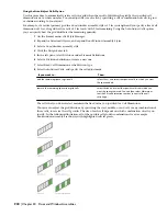
Select an alignment for the infill.
For more information, see “
Specifying an Alignment for a Door and Window Assembly Infill
” on page 926.
10
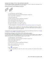
Specify an offset for the infill.
For more information, see “
Specifying an Offset for a Door and Window Assembly Infill
” on page 926.
11
Specify a thickness for the panel.
12
Click OK.
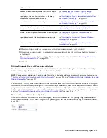
After you create an infill definition, you can assign it to any cell in a door/window assembly grid. For more information,
see “
Assigning Infills to Door and Window Assembly Cells
” on page 937.
Creating an Infill for Inserting an Object into a Door and Window Assembly
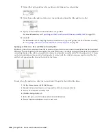
Use this procedure to create a style infill to insert objects into a door/window assembly. You can insert doors, windows,
curtain wall units, and AEC Polygons by defining a specific style of that object as an infill.
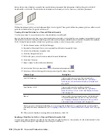
TIP After you insert an object in a cell, you can select that object independent of the grid and access editing options for the
object.
Because door/window assemblies can contain multiple infills, it is helpful to use a naming convention for panel infills
that indicates the infill location or purpose within the door/window assembly. For example, L3-FL1-Stone Panel identifies
a stone panel in a third-level grid on Floor 1.
NOTE The object styles you use in infills must exist in the current drawing to be added to an infill definition.
1
On the Format menu, click Style Manager.
2
Expand Architectural Objects, and expand Door/Window Assembly Styles.
3
Select a door/window assembly style.
4
Click the Design Rules tab.
5
In the left pane, select Infills under Element Definitions.
6
Click New Infill.
7
Enter a descriptive name for the infill.
8
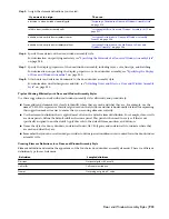
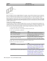
Select Style for Infill Type.
The right side of the dialog box changes to display a tree view of the object styles available for insertion
into a door/window assembly.
9
Select an object style.
Door and Window Assembly Styles | 925
Summary of Contents for 00128-051462-9310 - AUTOCAD 2008 COMM UPG FRM 2005 DVD
Page 1: ...AutoCAD Architecture 2008 User s Guide 2007 ...
Page 4: ...1 2 3 4 5 6 7 8 9 10 ...
Page 40: ...xl Contents ...
Page 41: ...Workflow and User Interface 1 1 ...
Page 42: ...2 Chapter 1 Workflow and User Interface ...
Page 146: ...106 Chapter 3 Content Browser ...
Page 164: ...124 Chapter 4 Creating and Saving Drawings ...
Page 370: ...330 Chapter 6 Drawing Management ...
Page 440: ...400 Chapter 8 Drawing Compare ...
Page 528: ...488 Chapter 10 Display System ...
Page 540: ...500 Chapter 11 Style Manager ...
Page 612: ...572 Chapter 13 Content Creation Guidelines ...
Page 613: ...Conceptual Design 2 573 ...
Page 614: ...574 Chapter 14 Conceptual Design ...
Page 678: ...638 Chapter 16 ObjectViewer ...
Page 683: ...Designing with Architectural Objects 3 643 ...
Page 684: ...644 Chapter 18 Designing with Architectural Objects ...
Page 788: ...748 Chapter 18 Walls ...
Page 942: ...902 Chapter 19 Curtain Walls ...
Page 1042: ...1002 Chapter 21 AEC Polygons ...
Page 1052: ...Changing a door width 1012 Chapter 22 Doors ...
Page 1106: ...Changing a window width 1066 Chapter 23 Windows ...
Page 1172: ...1132 Chapter 24 Openings ...
Page 1226: ...Using grips to change the flight width of a spiral stair run 1186 Chapter 25 Stairs ...
Page 1368: ...Using the Angle grip to edit slab slope 1328 Chapter 28 Slabs and Roof Slabs ...
Page 1491: ...Design Utilities 4 1451 ...
Page 1492: ...1452 Chapter 30 Design Utilities ...
Page 1536: ...1496 Chapter 31 Layout Curves and Grids ...
Page 1564: ...1524 Chapter 32 Grids ...
Page 1611: ...Documentation 5 1571 ...
Page 1612: ...1572 Chapter 36 Documentation ...
Page 1706: ...Stretching a surface opening Moving a surface opening 1666 Chapter 36 Spaces ...
Page 1710: ...Offsetting the edge of a window opening on a freeform space surface 1670 Chapter 36 Spaces ...
Page 1956: ...1916 Chapter 42 Fields ...
Page 2035: ...Properties of a detail callout The Properties of a Callout Tool 1995 ...
Page 2060: ...2020 Chapter 45 Callouts ...
Page 2170: ...2130 Chapter 47 AEC Content and DesignCenter ...
Page 2171: ...Other Utilities 6 2131 ...
Page 2172: ...2132 Chapter 48 Other Utilities ...
Page 2182: ...2142 Chapter 51 Reference AEC Objects ...
Page 2212: ...2172 Chapter 52 Customizing and Adding New Content for Detail Components ...
Page 2217: ...AutoCAD Architecture 2008 Menus 54 2177 ...
Page 2226: ...2186 Chapter 54 AutoCAD Architecture 2008 Menus ...
Page 2268: ...2228 Index ...

