


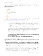


each wall style. However, in certain instances, you may need to override a display property for an individual wall to
achieve a specific result. All the display properties that you can specify in wall styles are available for individual walls:
■
Whether the display properties of wall components are determined by material assignments
■
The layer, color, and linetype of the display components of the wall
■
The hatching used with each component
■
The cut plane height and the display of components relative to the cut plane
■
Other specific wall display information, such as whether complex endcaps are displayed and whether the wall is
cut around door and window frames
When you change the display properties of an individual wall, the changes apply only to that wall. Other walls of the
same style are not affected. To change the display properties of all walls of a specific wall style, see “
Wall Styles
” on
page 722.
Specifying the Layer, Color, and Linetype of a Wall
Use this procedure to change the following display properties of the components of an individual wall:
■
Visibility (component is on or off)
■
By material (a material assigned to the display component determines its display properties)
■
Layer
■
Color
■
Linetype
■
Lineweight
■
Linetype scale
To change these display properties for all walls of the same wall style, see “
Specifying the Display Properties of a Wall
Style
” on page 733.
NOTE If a material assignment determines the properties of a wall display component, you can change the properties of the
display component by clearing By Material or by overriding the material assignment with a different material. For more
information, see
“
Specifying the Materials of Individual Walls
” on page 682
.
1
Select the wall you want to change, right-click, and click Edit Object Display.
NOTE You can also use the Display tab of the Properties palette to change the display property settings for a
selected object display component in the current display representation. For more information, see
“
Using the
Properties Palette to Change Display Properties
” on page 445
.
2
Click the Display Properties tab.
3
Select the display representation where you want the changes to appear, and select Object Override.
The display representation in bold is the current display representation.
4
If necessary, click
.
5
Click the Layer/Color/Linetype tab.
6
Select the component to change, and select a different setting for the property.
7
Click OK twice.
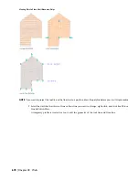
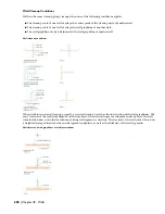
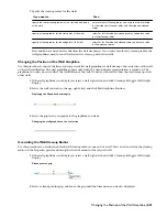
Specifying the Hatching for Components of a Wall
Use this procedure to specify the hatching of the components of an individual wall. Wall hatching is displayed only
in display representations, such as Plan, that are used in the Top view (plan view) of a drawing.
Changing the Display Properties of Individual Walls | 683
Summary of Contents for 00128-051462-9310 - AUTOCAD 2008 COMM UPG FRM 2005 DVD
Page 1: ...AutoCAD Architecture 2008 User s Guide 2007 ...
Page 4: ...1 2 3 4 5 6 7 8 9 10 ...
Page 40: ...xl Contents ...
Page 41: ...Workflow and User Interface 1 1 ...
Page 42: ...2 Chapter 1 Workflow and User Interface ...
Page 146: ...106 Chapter 3 Content Browser ...
Page 164: ...124 Chapter 4 Creating and Saving Drawings ...
Page 370: ...330 Chapter 6 Drawing Management ...
Page 440: ...400 Chapter 8 Drawing Compare ...
Page 528: ...488 Chapter 10 Display System ...
Page 540: ...500 Chapter 11 Style Manager ...
Page 612: ...572 Chapter 13 Content Creation Guidelines ...
Page 613: ...Conceptual Design 2 573 ...
Page 614: ...574 Chapter 14 Conceptual Design ...
Page 678: ...638 Chapter 16 ObjectViewer ...
Page 683: ...Designing with Architectural Objects 3 643 ...
Page 684: ...644 Chapter 18 Designing with Architectural Objects ...
Page 788: ...748 Chapter 18 Walls ...
Page 942: ...902 Chapter 19 Curtain Walls ...
Page 1042: ...1002 Chapter 21 AEC Polygons ...
Page 1052: ...Changing a door width 1012 Chapter 22 Doors ...
Page 1106: ...Changing a window width 1066 Chapter 23 Windows ...
Page 1172: ...1132 Chapter 24 Openings ...
Page 1226: ...Using grips to change the flight width of a spiral stair run 1186 Chapter 25 Stairs ...
Page 1368: ...Using the Angle grip to edit slab slope 1328 Chapter 28 Slabs and Roof Slabs ...
Page 1491: ...Design Utilities 4 1451 ...
Page 1492: ...1452 Chapter 30 Design Utilities ...
Page 1536: ...1496 Chapter 31 Layout Curves and Grids ...
Page 1564: ...1524 Chapter 32 Grids ...
Page 1611: ...Documentation 5 1571 ...
Page 1612: ...1572 Chapter 36 Documentation ...
Page 1706: ...Stretching a surface opening Moving a surface opening 1666 Chapter 36 Spaces ...
Page 1710: ...Offsetting the edge of a window opening on a freeform space surface 1670 Chapter 36 Spaces ...
Page 1956: ...1916 Chapter 42 Fields ...
Page 2035: ...Properties of a detail callout The Properties of a Callout Tool 1995 ...
Page 2060: ...2020 Chapter 45 Callouts ...
Page 2170: ...2130 Chapter 47 AEC Content and DesignCenter ...
Page 2171: ...Other Utilities 6 2131 ...
Page 2172: ...2132 Chapter 48 Other Utilities ...
Page 2182: ...2142 Chapter 51 Reference AEC Objects ...
Page 2212: ...2172 Chapter 52 Customizing and Adding New Content for Detail Components ...
Page 2217: ...AutoCAD Architecture 2008 Menus 54 2177 ...
Page 2226: ...2186 Chapter 54 AutoCAD Architecture 2008 Menus ...
Page 2268: ...2228 Index ...


