


■
5 = Details
■
6 = Schedules and Diagrams
■
7 = User Defined
■
8 = User Defined
■
9 = 3D Representations (Isometrics, Perspectives and Photographs)
Examples:
■
A-101 - (Architectural First Floor Plan)
■
A-102 - (Architectural Second Floor Plan)
■
A-103 - (Architectural First Floor Reflected Ceiling Plan)
■
A-201 - (Architectural Building Elevations)
■
A-301 - (Architectural Building Sections)
Here again, the codes are very broad, so it is certainly possible on a big project to run out of numbers. Many firms
develop similar systems of naming, but conceptually they are usually very consistent with these. One factor to consider,
while there is neither a functional nor philosophical reason why existing sheet file naming in your firm cannot simply
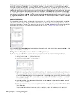
be adopted, the integration of the Sheet Set Manager within Project Navigator introduces some hard-coded assumptions
about sheet file naming that may be different than your current system. When you name a new sheet on Project
Navigator’s Sheets tab, you input both the sheet number and the sheet title. These two values, which will ultimately
feed two different fields on the title block, are by default concatenated together to form the sheet file name. It is likely
that this is in variance to how you name sheets today. Whether or not it will prove problematic is another matter. In
most cases it is arguable that this change in naming will have little to no impact on your work flow or process.
Considering the level of automation that Sheet Set manager provides, give this new approach some serious consideration
before adopting a contrary policy that may actually prove harder to manage.
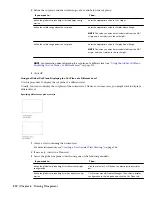
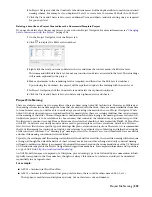
Understanding Constructs Included in the Commercial Template Project
All constructs included in the Commercial Template Project are suggestions of typical commercial project organization.
Feel free to modify the arrangement to suit your specific project needs and add or delete files as needed. Some files may
contain geometry; these are placeholders that are meant to be erased by project team members prior to beginning work.
Simply erase the geometry, and draw actual project geometry in its place. For example, the Typical Toilet Room element
file contains a rectangle, and many files include a Live Area Guide block insertion.
General Considerations for all Constructs
Typically there will be at least one construct for each level and/or division (if used). However, there will often be many
more than that. Project and team member requirements will be a determining factor in shaping the exact quantity and
makeup of the constructs on a per-project basis. Some projects will have many constructs per floor, while others might
have only one per floor. Below is a brief description of each construct included in this Commercial Template Project.
Feel free to add or delete them as required to meet your specific project and team needs. You can also make modifications
to the Commercial Template Project and resave it as a custom template project for use in later projects.
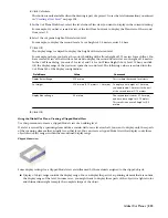
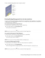
Terrain Construct
This construct is intended for a simple terrain model of the project’s site conditions. Use the mass element Drape tool
(on the Massing palette - Design Tool Palette Group) to create such a terrain model from Polyline contours. For more
information, see “
Creating a Drape Mass Element
” on page 583. Polylines can be imported from a civil engineer’s file
or simply drawn. Place each polyline at the height of the contour (you can do this easily on the Properties palette using
the Elevation property). To carve away the footprint of the building from the terrain, you can use a Boolean operation,
as described in “
Combining Mass Elements Using Boolean Operations
” on page 594. This will help sections display
better later on.
The Terrain construct is referenced in the Site Plan, Composite Model, Section and Elevation View files.
Shell Construct
Several shell constructs have been included into the Commercial Template Project: one for each floor of the building.
These constructs are intended for the exterior enclosure of the building on each floor. Include walls, doors, windows,
assemblies and curtain walls into the shell as necessary. All objects in these constructs ought to span only one floor. If
you have a curtain wall that spans multiple floors, you should create a separate spanning Facade construct that includes
a multi-level curtain wall object. To make a construct spanning, check more than one level or division. Although it
Understanding Constructs Included in the Commercial Template Project | 325
Summary of Contents for 00128-051462-9310 - AUTOCAD 2008 COMM UPG FRM 2005 DVD
Page 1: ...AutoCAD Architecture 2008 User s Guide 2007 ...
Page 4: ...1 2 3 4 5 6 7 8 9 10 ...
Page 40: ...xl Contents ...
Page 41: ...Workflow and User Interface 1 1 ...
Page 42: ...2 Chapter 1 Workflow and User Interface ...
Page 146: ...106 Chapter 3 Content Browser ...
Page 164: ...124 Chapter 4 Creating and Saving Drawings ...
Page 370: ...330 Chapter 6 Drawing Management ...
Page 440: ...400 Chapter 8 Drawing Compare ...
Page 528: ...488 Chapter 10 Display System ...
Page 540: ...500 Chapter 11 Style Manager ...
Page 612: ...572 Chapter 13 Content Creation Guidelines ...
Page 613: ...Conceptual Design 2 573 ...
Page 614: ...574 Chapter 14 Conceptual Design ...
Page 678: ...638 Chapter 16 ObjectViewer ...
Page 683: ...Designing with Architectural Objects 3 643 ...
Page 684: ...644 Chapter 18 Designing with Architectural Objects ...
Page 788: ...748 Chapter 18 Walls ...
Page 942: ...902 Chapter 19 Curtain Walls ...
Page 1042: ...1002 Chapter 21 AEC Polygons ...
Page 1052: ...Changing a door width 1012 Chapter 22 Doors ...
Page 1106: ...Changing a window width 1066 Chapter 23 Windows ...
Page 1172: ...1132 Chapter 24 Openings ...
Page 1226: ...Using grips to change the flight width of a spiral stair run 1186 Chapter 25 Stairs ...
Page 1368: ...Using the Angle grip to edit slab slope 1328 Chapter 28 Slabs and Roof Slabs ...
Page 1491: ...Design Utilities 4 1451 ...
Page 1492: ...1452 Chapter 30 Design Utilities ...
Page 1536: ...1496 Chapter 31 Layout Curves and Grids ...
Page 1564: ...1524 Chapter 32 Grids ...
Page 1611: ...Documentation 5 1571 ...
Page 1612: ...1572 Chapter 36 Documentation ...
Page 1706: ...Stretching a surface opening Moving a surface opening 1666 Chapter 36 Spaces ...
Page 1710: ...Offsetting the edge of a window opening on a freeform space surface 1670 Chapter 36 Spaces ...
Page 1956: ...1916 Chapter 42 Fields ...
Page 2035: ...Properties of a detail callout The Properties of a Callout Tool 1995 ...
Page 2060: ...2020 Chapter 45 Callouts ...
Page 2170: ...2130 Chapter 47 AEC Content and DesignCenter ...
Page 2171: ...Other Utilities 6 2131 ...
Page 2172: ...2132 Chapter 48 Other Utilities ...
Page 2182: ...2142 Chapter 51 Reference AEC Objects ...
Page 2212: ...2172 Chapter 52 Customizing and Adding New Content for Detail Components ...
Page 2217: ...AutoCAD Architecture 2008 Menus 54 2177 ...
Page 2226: ...2186 Chapter 54 AutoCAD Architecture 2008 Menus ...
Page 2268: ...2228 Index ...


