Concepts and Features
R&S
®
ZNB/ZNBT
217
User Manual 1173.9163.02 ─ 53
The distance to fault measurement of option R&S
ZNB-K3/R&S
ZNBT-K3 is currently
restricted to port 2. A more flexible approach with additional configuration possibilities
is available with time domain option R&S
ZNB-K2 / R&S
ZNBT-K2 (see
5.7.4
Frequency Conversion Measurements
Option R&S
ZNB/ZNBT-K4
With option R&S
ZNB/ZNBT-K4, the frequencies of the source ports can be configured
independently. The source and receive frequencies of the ports are always equal. Arbi-
trary port settings represent a major extension to the analyzer's measurement function-
ality; in particular they allow you to measure frequency-converting DUTs.
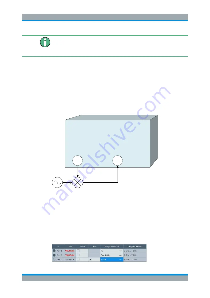
The following figure shows a transmission measurement on a mixer.
VNA
1
2
RF
LO
IF
f
IF, up
= f
RF
+ f
LO
f
IF, down
= | f
RF
- f
LO
|
In this example, the transmission parameter S
21
corresponds to the mixer's conversion
gain.
Before measuring, the port frequencies must be set appropriately. In the port configura-
tion table (CHANNEL – [CHANNEL
CONFIG] > "Port Config" > "Port Settings..." > "Arb
Frequency"), the (source) frequency of Port 1 is set to the desired RF frequency (here:
the channel base frequency/sweep range f
b
). An external generator provides a fixed
stimulus signal at 1 GHz. To measure the up-converted IF signal, the (receive) fre-
quency at Port 2 is set to f
b
+ 1 GHz.
Optional Extensions and Accessories


