


PWMA_SMnCTRL2 field descriptions (continued)
Field
Description
• The PWM_A and PWM_B output pins will assume values based on DTSRCSEL[SMxSEL23] and
DTSRCSEL[SMxSEL45].
• If CTRL2[FRCEN] is set, the counter value will be initialized with the INIT register value.
5–3
FORCE_SEL
This read/write bit determines the source of the FORCE OUTPUT signal for this submodule.
000
The local force signal, CTRL2[FORCE], from this submodule is used to force updates.
001
The master force signal from submodule 0 is used to force updates. This setting should not be used
in submodule 0 as it will hold the FORCE OUTPUT signal to logic 0.
010
The local reload signal from this submodule is used to force updates without regard to the state of
LDOK.
011
The master reload signal from submodule0 is used to force updates if LDOK is set. This setting
should not be used in submodule0 as it will hold the FORCE OUTPUT signal to logic 0.
100
The local sync signal from this submodule is used to force updates.
101
The master sync signal from submodule0 is used to force updates. This setting should not be used
in submodule0 as it will hold the FORCE OUTPUT signal to logic 0.
110
The external force signal, EXT_FORCE, from outside the PWM module causes updates.
111
The external sync signal, EXT_SYNC, from outside the PWM module causes updates.
2
RELOAD_SEL
Reload Source Select
This read/write bit determines the source of the RELOAD signal for this submodule. When this bit is set,
MCTRL[LDOK[0]] for submodule 0 should be used since the local MCTRL[LDOK] will be ignored.
0
The local RELOAD signal is used to reload registers.
1
The master RELOAD signal (from submodule 0) is used to reload registers. This setting should not be
used in submodule 0 as it will force the RELOAD signal to logic 0.
CLK_SEL
Clock Source Select
These read/write bits determine the source of the clock signal for this submodule.
00
The IPBus clock is used as the clock for the local prescaler and counter.
01
EXT_CLK is used as the clock for the local prescaler and counter.
10
Submodule 0’s clock (AUX_CLK) is used as the source clock for the local prescaler and counter.
This setting should not be used in submodule 0 as it will force the clock to logic 0.
11
reserved
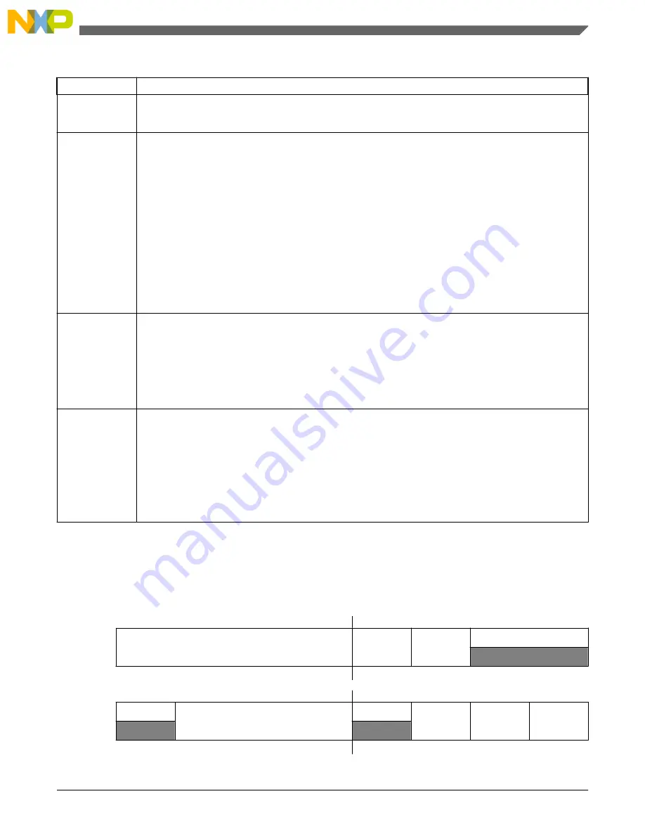
37.4.4 Control Register (PWMA_SMnCTRL)
Address: 4003_3000h base + 6h (96d × i), where i=0d to 3d
Bit
15
14
13
12
11
10
9
8
Read
Write
Reset
0
0
0
0
0
1
0
0
Bit
7
6
5
4
3
2
1
0
Read
Write
Reset
0
0
0
0
0
0
0
0
Chapter 37 Pulse Width Modulator A (PWMA/eFlexPWM)
KV4x Reference Manual, Rev. 2, 02/2015
Freescale Semiconductor, Inc.
Preliminary
783
Summary of Contents for freescale KV4 Series
Page 2: ...KV4x Reference Manual Rev 2 02 2015 2 Preliminary Freescale Semiconductor Inc...
Page 60: ...KV4x Reference Manual Rev 2 02 2015 60 Preliminary Freescale Semiconductor Inc...
Page 128: ...Debug Security KV4x Reference Manual Rev 2 02 2015 128 Preliminary Freescale Semiconductor Inc...
Page 138: ...Boot KV4x Reference Manual Rev 2 02 2015 138 Preliminary Freescale Semiconductor Inc...
Page 1358: ...KV4x Reference Manual Rev 2 02 2015 1358 Preliminary Freescale Semiconductor Inc...


