


MPC563XM Reference Manual, Rev. 1
836
Freescale Semiconductor
Preliminary—Subject to Change Without Notice
Match/Transition Pin Action Conflict Resolution
In output signals, matches and/or transitions automatically cause pin actions defined by the OPAC1/2
and/or IPAC1/2 channel control registers (see
Section 23.4.5.1.2, “Pin Control Registers
). Simultaneous
matches/transitions may be associated with different, possibly contradictory, pin actions. These conflicts
are resolved according to the
If an OPAC1/2=000 (no action) prevails over non-zero OPAC according to
, then if
match1/transition1 and match2/transition2 occur simultaneously, no output pin action occurs, that is: a
match on the action logic with OPAC=000 inhibits simultaneous actions of the other OPAC, if prevailing
according to
. That also applies when output actions are caused by inputs (OPAC=1xx).
23.4.5.4.5
Combining Input and Output Signals
The processing of input signal can be combined with output signal generation. A detected input transition
can trigger an output signal edge, even without microcode intervention, by using OPAC options 1xx.
The channel set-up examples below show these two capabilities combined (see
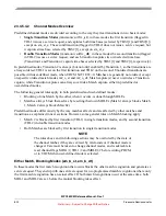
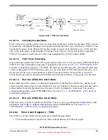
The
first example
implements a fast (no microcode intervention) short-circuit protection feedback
mechanism for driving high-current output devices. The signal after the high-current driver feeds back to
the channel input. The input signal is normally delayed from the output signal by the device turn-on delay.
After the channel output turns on, the channel logic must check if the driver output (connected to the
channel input) follows the driven value after the maximum device turn-on delay. If it does not, the driver
output is probably shorted, and the channel output must be turned off immediately to avoid damaging the
device.
Match 1 causes the output to be driven high (for simplicity the output and input signals are shown as
positive logic). It also causes a transition 1, because IPAC1=100 and the input is still low. Match 2 occurs
after the expected driver delay, and causes a service request. If the output is shorted, a Transition 2 occurs
on Match 2 because IPAC2=100. This will cause the output to go low immediately, because OPAC2=100.
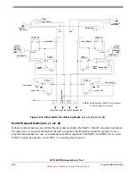
In the
second example
, an output pulse is generated from an input transition without microcode
intervention. Match 1 opens a window for transitions and also enables Match 2. A rising edge on input sets
output high. On Match 2 the window closes, and input signal is checked: if sampled high, the output resets;
otherwise it stays high.
Table 23-36. Simultaneous Match Pin Action Priority
Channel Mode
Priority
em_nb_st / em_nb_dt
OPAC1
em_b_st / em_b_dt
OPAC1
bm_st / bm_dt
OPAC1
m2_st / m2_dt
OPAC2
m2_o_st / m2_o_dt
in these modes there is no possibility
of simultaneous matches
user-defined
OPAC2 if M2BM1 = 1 and M1BM2 = 0,
OPAC1 otherwise


