


MPC563XM Reference Manual, Rev. 1
Freescale Semiconductor
801
Preliminary—Subject to Change Without Notice
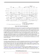
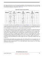
Figure 23-39. Channel Logic Block Diagram
Input Signal
TCR1
TCR2
Capture 1
Match 1
TBS1[0]
TBS1[1]
ER1 Bus
TBS1[2]
0: >=
1: ==
MRLE1
MRL1
TDL1
ucode ERW1 & CMW=1
Set
Rst
ucode
MRL1
Rst
Set
Rst
ucode MRLE
Set
Action Logic 1
Trans.1
Match 1
to service request
Transition
Event
Logic
OPAC1
IPAC1
Capture 2
Match 2
TBS2[0]
TBS2[1]
ER2 Bus
TBS2[2]
0: >=
1: ==
MRLE2
MRL2
TDL2
ucode ERW2
Set
Rst
ucode
MRL2
Rst
Set
Rst
ucode MRLE
Set
Action Logic 2
Trans.2
Match2
OPAC2
IPAC2
EDF
Output FF
Output
Logic
Set
Rst
OBE
FF
ucode TBS1[2:0]
PDCM
SRI
SRI
ucode
MTD
Rst
Set
ucode PDCM
ucode IPAC1
ucode IPAC2
ucode
OPAC1
ucode
OPAC2
Output Signal
Output Buffer Enable
ETPUTBCR[CDCF]
to branch
PSTI
to branch
PSTO
PSC, PSCS
ucode
Channel
Flags
Flag0
Flag1
ucode FLC
Comparator
Comparator
ODIS
OPOL
Microengine
Microengine
MEF
(Filter)
ucode
TDL
ucode
TDL
to service request
to branch
TDL2
to branch
MRL2
to branch
TDL1
to branch
MRL1
control
Transition
Event
Logic
Match
Recognition
Match
Recognition
ETPUECR[FPSCK]
TCRCLK
Filter
Input Signal
= Channel 0 only
AM
ipp_obe_etpuch
AM
Synchr.
Synchr.
UDCM
mode
decoding
ucode ERW1
& CMW=0
TCRCLK
channel input
channel output
TCCE1
ucode
MTD


