


MPC563XM Reference Manual, Rev. 1
Freescale Semiconductor
225
Preliminary—Subject to Change Without Notice
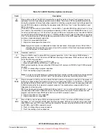
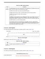
If the user attempts to write two or more MCR bits simultaneously then only the bit with the lowest priority
level is written. Setting two bits with the same priority level is prevented by existing write locks or do not
put the flash in an illegal state.
For example, setting ERS and PGM simultaneously results in only ERS being set. Attempting to clear
EHV while setting PSUS results in EHV being cleared, while PSUS is unaffected.
10.3.6.2
Low/Mid Address Space Block Locking Register
The Low/Mid Address Block Locking Register (LML) provides a means to protect blocks from being
modified. These bits, along with bits in the Secondary LLOCK (SLL), determine if the block is locked
from program or erase. An “OR” of LML and SLL determine the final lock status.
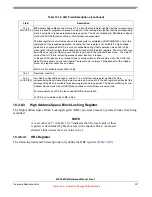
NOTE
A reset value of 1* in
indicates that the reset value of these
registers is determined by Flash values in the shadow block. An erased
shadow block causes the reset value to be 1.
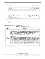
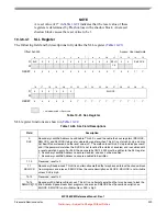
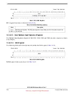
10.3.6.2.1
LML Register
The following field and bit descriptions fully define the LML register (
).
3
EHV
4
ESUS, PSUS
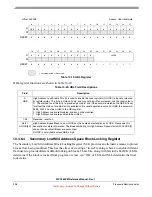
Table 10-16. MCR Bit Set/Clear Priority Levels
Priority Level
MCR Bit(s)


