


MPC563XM Reference Manual, Rev. 1
818
Freescale Semiconductor
Preliminary—Subject to Change Without Notice
A generic description of channel modes from the usage point of view can be found in
.” Each mode is named with a mnemonic acronym for terse reference. The
individual programmed attributes of the user-programmable channel mode are also described.
The modes are used differently for input and output signals, as explained in
“Predefined Channel Modes on Input Signal Processing
Section 23.4.5.4.4, “Channel Modes on
.” Modes also allow combining input processing and output generation in a
single channel, as exemplified in
Section 23.4.5.4.5, “Combining Input and Output Signals
.
Section 23.4.5.4.1, “Channel Mode Logic and Event Flags
” shows a structural definition of channel logic
and its relation to channel modes. A dynamic, event-oriented view of each channel mode can be found in
Section 23.6.3, “Predefined Channel Mode Summary
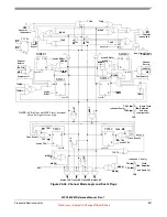
23.4.5.4.1
Channel Mode Logic and Event Flags
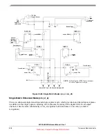
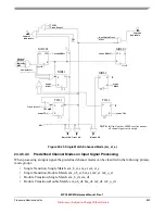
shows a more detailed diagram of channel mode logic. The logic shown here is not
necessarily identical to the actual channel logic implementation, but is equivalent with respect to
conditions for event blocking, enabling, capture, and service requests.
Signals MSR, TSR, MCAP, TCAP, M1ET, M1EM2, M1BM2, M2BM1, M2BT, T1BM1, T2BM1, TBM2
and T1ET2 are decoded from programmed channel mode PDCM in predefined modes, and come directly
from the UDCM register when user-defined mode is selected:
•
TSR (1 bit) defines Service Requests issued by Transitions, as shown in
•
MSR (2 bits) defines Service Requests issued by Matches, as shown in
.
•
TCAP (1 bit) defines time base captures caused by Transitions, as shown in
•
MCAP (1bit) defines time base captures caused by Matches, as shown in
.
•
M1ET, M1EM2, M1BM2, M2BM1, M2BT, T1BM1, T2BM1, TBM2, T1ET2 (1 bit each) define
Match and Transition reciprocal blocking and enabling, as well as Transition ordering, as shown in
.
shows the decoded values of those control signals for each predefined channel mode. The first
column shows the mnemonic reference for the predefined channel modes described in the following
sections.
Changing PDCM or the UDCM when user mode is selected may set or reset any of the channel flags, or
issue captures and service requests, so it is advisable to switch channel modes only in a quiescent channel
state, with channel flags MRLE1/2, TDL1/2, MRL1/2 cleared. Furthermore, an event flag asserted in one
mode may keep asserted after the mode programming change, even if the flag is impossible to be set in the
new mode.
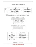
Table 23-30. MSR[1:0] signals - Match Service Requests
value
MSR
00
issue no Service Requests on Matches
01
issue Service Request on Match 2 only
10
issue Service Request on 2nd
1
Match
11
issue Service Request on both Matches


