


MPC563XM Reference Manual, Rev. 1
Freescale Semiconductor
1355
Preliminary—Subject to Change Without Notice
Bits [27:22] indicate the design center.
PIN — Part Identification Number
Bits [21:12] contain the part number of the device.
MIC — Manufacturer Identity Code
Bits [11:1] contain the reduced Joint Electron Device Engineering Council (JEDEC) ID.
Bit [0] — IDCODE Register ID
Bit [0] identifies this register as the device identification register and not the bypass register
31.4.1.4
CENSOR_CTRL Register
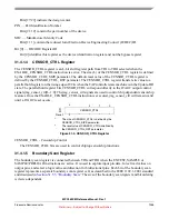
The CENSOR_CTRL register is an L-bit shift register path from TDI to TDO selected when the
ENABLE_CENSOR_CTRL instruction is active. The size (L) of the CENSOR_CTRL register is defined
by the CENSOR_CTRL_SIZE parameter. The default reset value of the CENSOR_CTRL register is
defined by the CENSOR_CTRL_RST parameter. The CENSOR_CTRL register transfers its value to a
parallel hold register on the rising edge of TCK when the TAP controller state machine is in the Update-DR
state. The parallel hold register bits CENSOR_CTRL correspond directly to the JTAGC output control
signals jtag_censor_ctrl[L-1:0]. The jtag_censor_ctrl signals are used to control chip dependent censorship
features. Once the ENABLE_CENSOR_CTRL instruction is executed, jtag_censor_ctrl will remain valid
until a JTAGC reset occurs.
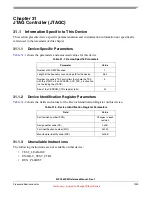
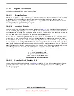
Figure 31-4. CENSOR_CTRL Register
CENSOR_CTRL - Censorship Control
The CENSOR_CTRL bits are used to control chiptop censorship functions.
31.4.1.5
Boundary Scan Register
The boundary scan register is connected between TDI and TDO when the EXTEST, SAMPLE or
SAMPLE/PRELOAD instructions are active. It is used to capture input pin data, force fixed values on
output pins, and select a logic value and direction for bidirectional pins. Each bit of the boundary scan
register represents a separate boundary scan register cell, as described in the IEEE 1149.1-2001 standard
and discussed in
Section 31.5.5, “Boundary Scan.”
The size of the boundary scan register and bit ordering
is device-dependent.
*
1
1
The size of CENSOR_CTRL is defined by the
CENSOR_CTRL_SIZE parameter.
...
2
1
0
R
CENSOR_CTRL
W
Reset:
*
2
2
The reset value of CENSOR_CTRL is defined by
the CENSOR_CTRL_RST parameter.
*
*
*
*


