


MPC563XM Reference Manual, Rev. 1
Freescale Semiconductor
691
Preliminary—Subject to Change Without Notice
NOTE
FORCMA and FORCMB have the same behavior even in Freeze or normal
mode regarding the output pin transition.
When
FORCMA
is issued along with
FORCMB
the output flip-flop is set to the opposite of EDPOL bit
value. This is equivalent of saying that
.FORCMA
has precedence over
FORCMB
when lead dead time
insertion is selected and
FORCMB
has precedence over
FORCMA
when trail dead time insertion is
selected.
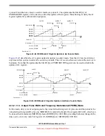
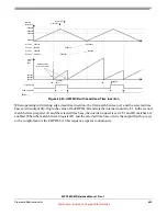
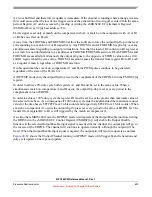
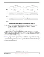
Duty cycle from 0% to 100% can be generated by setting appropriate values to A1 and B1 registers
relatively to the period of the external time base. Setting A1=1 generates a 100% duty cycle waveform.
Assuming EDPOL is set to one and OPWMCB mode with trail dead time insertion, 100% duty cycle
signals can be generated if B1 occurs at or after the cycle boundary (external counter = 1). If A1 is greater
than the maximum value of the selected counter bus period, then a 0% duty cycle is produced, only if the
pin starts the current cycle in the opposite of EDPOL value. In case of 100% duty cycle, the transition from
EDPOL to the opposite of EDPOL may be obtained by forcing pin, using FORCMA and/or FORCMB.
NOTE
If A1 is set to $1 at OPWMCB entry the 100% duty cycle may not be
obtained in the very first PWM cycle due to the pin condition at mode entry.
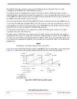
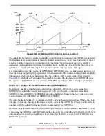
Only values different than $0 are allowed to be written to A1 register. If $0 is loaded to A1 the results are
unpredictable.
NOTE
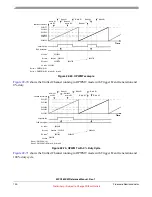
A special case occurs when A1 is set to (external counter bus period)/2,
which is the maximum value of the external counter. In this case the output
flip-flop is constantly set to the EDPOL bit value.
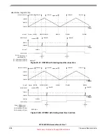
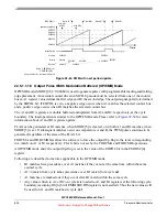
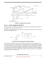
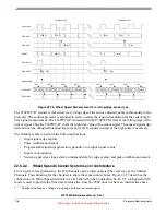
The internal channel logic prevents matches from one cycle to propagate to the next cycle. In trail dead
time insertion B1 match from cycle
n
could eventually cross the cycle boundary and occur in cycle
n+1
.
In this case B1 match is masked out and does not cause the output flip-flop to transition. Therefore matches
in cycle
n+1
are not affected by the late B1 matches from cycle
n
.
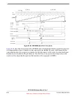
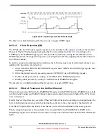
shows a 100% duty cycle output signal generated by setting A1=4 and B1=3. In this case the
trailing edge is positioned at the boundary of cycle
n+1
, which is actually considered to belong to cycle
n+2
and therefore does not cause the output flip-flip to transition.


