


MPC563XM Reference Manual, Rev. 1
Freescale Semiconductor
935
Preliminary—Subject to Change Without Notice
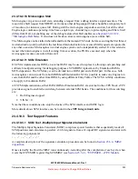
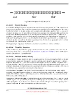
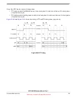
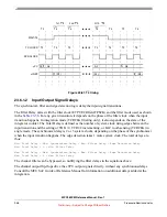
Figure 23-71. First-Pass Worst-Case Latency
To estimate worst-case latency:
•
Find the worst-case service time for each active channel.
•
Using the H-M-H-L-H-M-H time-slot sequence, map the channels that are granted for each time
slot.
•
Add time for six-clock time-slot transitions.
Finding the Worst-Case Service Time for Each Active Channel
A table for eTPU functions should list the longest threads (not counting initialization threads) for the
functions, and the number of eTPU SPRAM accesses in the longest thread (semaphored and non
semaphored). These figures will be used for estimating Microengine wait time.
is an example
for old TPU functions in which there are only simple parameter RAM accesses. It does not take into
consideration the CDC operation and Microengine to Microengine communication.
The worst-case service time for each channel is: (CPCR=CCR=0)
Longest ((number of RAM accesses in longest 1) * RCR * 2 clocks). Note that the formula
adds 1 RAM accesses for the parameter preload that occurs during TST. There are actually three accesses
during TST, but only the first one can receive wait-states.
Table 23-101. Longest Threads and RAM Accesses for old TPU Functions
Function
Longest Thread RAM Accesses
DIO
10
4
ITC
40 (no linking)
42 (linking)
7
OC
40
7
PWM
24
4
SPWM
Mode 0
Mode1
Mode 2
14
18
20 (no linking)
22 (linking
4
4
4
4
PMA
94
8
PMM
94
8
Channel X
Serviced
Worst Case Latency Channel X
Other Channels Serviced
Channel X
Serviced Next


