


MPC563XM Reference Manual, Rev. 1
Freescale Semiconductor
1119
Preliminary—Subject to Change Without Notice
25.4.2
Decimation Filter Registers Description
All registers are 32-bit wide.
25.4.2.1
Configuration Register (DECFILTER_MCR)
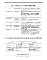
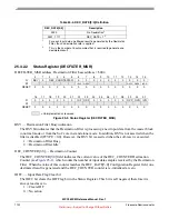
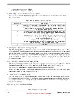
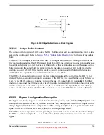
DECFILTER_MCR address: Decimation Filter base a $000
Figure 25-2. Configuration Register (DECFILTER_MCR)
The Decimation Filter Configuration register provides configuration control bits for the Decimation Filter
internal logic. It is not allowed to write in this register when the status bit BSY is set.
MDIS — Module Disable
The MDIS bit puts the Decimation Filter in low power mode. Communication through the PSI
sky-blue Interface is ignored in this mode. Writes to the Configuration register are allowed with
exception of writes to the FREN, SRES bits that are ignored. Writes to the Coefficient registers are
also allowed. The Decimation Filter cannot enter Freeze mode once in disable mode. The
ipg_enable_clk output goes to disable and ipg_clk is stopped.
1 = Low Power Mode
0 = Normal Mode
FREN — Freeze Enable
The FREN bit enables the Decimation Filter to enter freeze mode if the ipg_debug signal or the FRZ
bit is asserted. Refer to
Section 25.5.12, “Freeze Mode Description,”
for more details.
1 = Decimation Filter Freeze mode enabled
0 = Decimation Filter Freeze mode disabled
FRZ— Freeze Mode
1
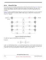
The TAP register is responsible to store the input sample data and the Filter intermediary results on each Filter
node.
0
1
2
3
4
5
6
7
8
9
10
11
12
13
14
15
R
MDI
S
FRE
N
0
FRZ
0
0
0
IDEN
ODEN
ER-
REN
0
FTYPE[1:0]
0
SCAL[1:0]
W
SRE
S
RESET:
Note
1
1
Reset value is defined by the MDIS_DEFAULT parameter value.
0
0
0
0
0
0
0
0
0
0
0
0
0
0
0
16
17
18
19
20
21
22
23
24
25
26
27
28
29
30
31
R
0
SAT ISEL
0
DEC_RATE[3:0]
0
0
0
0
0
0
0
0
W
RESET:
0
0
0
0
0
0
0
0
0
0
0
0
0
0
0
0
= Unimplemented or reserved


