


MPC563XM Reference Manual, Rev. 1
614
Freescale Semiconductor
Preliminary—Subject to Change Without Notice
BOOT_BLOCK_ADDRESS is the address from
where the BAM finds a valid RCHW. If the
BAM program finds a valid RCHW, the core watchdog is enabled if the RCHW[WTE] bit is programmed
high, the SWT is disabled if the RCHW[SWT] bit is programmed low, the BAM program fetches the reset
vector from the address of the BOOT_BLOCK_A 0x4, and branches to the reset boot vector
(shown in
). A user application should have a valid instruction at the reset boot vector address.
21.5.5
Serial Boot Mode
When the BAM program transitions to the Serial Boot mode unused message buffers in CAN_A are used
for the BAM program stack and variables, the SWT watchdog is reprogrammed with longer than default
timeout period.
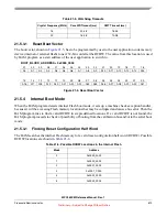
The MMU setup depends the way how the BAM entered the serial boot mode. If the try to boot from
calibration bus was made, the MMU is set up as for that mode (see
). If the part is not in CSP
package, the MMU setup matches the
.
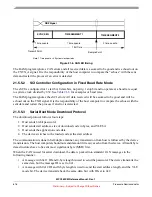
The serial boot mode can run in either of two modes of operation:
•
Standard serial boot mode using fixed baud rates derived from the crystal oscillator used
•
Baud Rate Detection serial boot mode, which allows communication with adaptable speed, based
on measured input signal
The Fixed Baud Rate mode or Baud Rate Detection mode are selected based on the state of the EVTO pin,
recorded in the SIU_RSR[ABR] bit. If the bit is set, the Baud Rate Detection mode is selected if the bit is
cleared, the Fixed Baud Rate is selected,
The SIU_RSR[ABR] bit reflects the inverted state of the EVTO pin, thus to select Baud Rate Detection
mode, the EVTO pin needs to be driven low.
When the Fixed Baud Rate mode is selected, the BAM program configures the RXD_A pin to be the input
of the eSCI_A module, CNRX_A pin as an input and CNTX_A as an output of the CAN_A module.
When Baud Rate Detection Mode is selected, the BAM program configures RXD_A and CNRX_A pins
as GPI inputs for polling their state by the CPU.
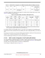
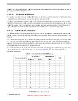
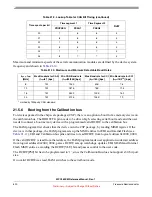
The SCI and CAN controllers pins configuration summary is shown in the
Table 21-7. CAN/eSCI Pins Configuration for CAN/eSCI Fixed Baud Rate Boot Modes
Pins
Reset
Function
Initial Serial Boot Mode
Serial Boot Mode after a valid
CAN message received
Serial Boot Mode after a valid
eSCI message received
Function
Pad
Configuration
Function
Pad
Configuration
Function
Pad
Configuration
CNTX_A
GPIO
CNTX_A
Push/Pull output,
with medium slew
rate
CNTX_A
Push/Pull output,
with medium slew
rate
GPIO
-
CNRX_A
GPIO
CNRX_A
Input with pull-up
and hysteresis
CNRX_A
Input with pull-up
and hysteresis
GPIO
-


