


MPC563XM Reference Manual, Rev. 1
Freescale Semiconductor
1071
Preliminary—Subject to Change Without Notice
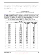
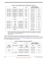
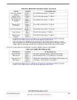
GCC_INT - Integer part of the gain calibration constant for ADC0/1
GCC_INT is the integer part of the gain calibration constant for ADC0/1.
GCC_FRAC[1:14] - Fractional part of the gain calibration constant for ADC0/1
GCC_FRAC is the fractional part of the gain calibration constant for ADC0/1. GCC_FRAC can
expresses decimal values ranging from 0 to 0.999938...
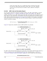
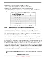
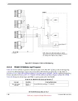
24.6.6.7
ADC Control Logic
overview and command execution
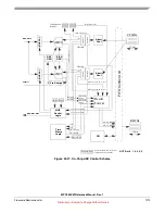
shows the basic logic blocks involved in the ADC Control and how they interact.
CFIFOs/RFIFOs interact with CBuffers/
Abort Cont
/
Result Message Return Logic
through the
FIFO
Control Unit
. The EB and BN bits in the Command Message uniquely identify the CBuffer to which a
command should be sent. The
FIFO Control Unit
decodes these bits and sends the ADC command to the
proper CBuffer. Other blocks of logic are the
Resolution Adjustment
,
Result Format and Calibration
Sub-Block
, the
Time Stamp Logic,
and the
MUX Control Logic
.
The
Resolution Adjustment Sub-Block
receives the 12-bit data bus directly from the ADC and changes the
received conversion results from right aligned format of ADC to the left aligned format depending on the
selected resolution of the conversion. This operation helps the calibration processing to use the calibration
coefficients always with the same format.
The
Result Format and Calibration Sub-Block
formats the returning data into Result Messages and sends
them to the RFIFOs
1
. The returning data can be data read from an ADC register, a conversion result, or a
time stamp. The formatting and calibration of conversion results also take place inside this sub-block.
The
Time Stamp Logic
latches the value of the time base counter when detecting the end of the analog input
voltage sampling, and sends it to the
Result Format and Calibration Sub-Block
as time stamp information.
The
MUX Control Logic
generates the proper MUX control signals and, when the ADC0/1_EMUX bits
are asserted, the MA signals based on the channel numbers extracted from the ADC Command.
Table 24-29. Binary and Decimal Representations of the Gain Constant
Gain Constant
(GCC_INT.GCC_FRAC binary format)
Corresponding Decimal Value
0.0000_0000_0000_00
0
...
...
0.1000_0000_0000_00
0.5
...
...
0.1111_1111_1111_11
0.999938...
1.0000_0000_0000_00
1
...
...
1.1100_0000_0000_00
1.75
...
...
1.1111_1111_1111_11
1.999938...
1.
The result messages may also be routed to an on-chip companion module via the side interface, and then fed back to the
RFIFOs.


