


MPC563XM Reference Manual, Rev. 1
Freescale Semiconductor
711
Preliminary—Subject to Change Without Notice
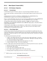
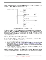
22.5.3.1
Effect of Freeze on the BIU
When the FRZ bit in the EMIOSMCR register is set and the module is in debug mode, the operation of
BIU is not affected.
22.5.4
Red Line Client submodule (REDC)
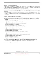
The REDC provides one external time base, imported from Red Line bus (also called STAC bus), to the
Unified Channels.
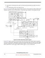
provides a block diagram for the REDC module.
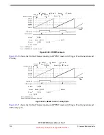
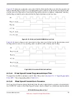
Figure 22-81. REDC block diagram
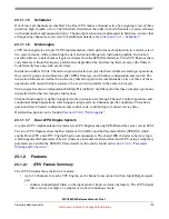
Bits SRV[0:3] in register EMIOSMCR, selects the desired time slot of the Red-line bus to be output.
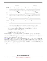
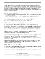
shows a timing diagram for the REDC.
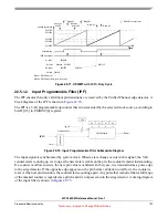
Figure 22-82. Timing diagram for the Red Line bus and REDC output
Every time the selected time slot change, the REDC output is updated.
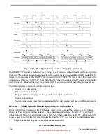
22.5.4.1
Effect of Freeze on the REDC
When the FRZ bit in the EMIOSMCR register is set and the module is in debug mode, the operation of
REDC submodule is not affected, i.e., there is no freeze function in this submodule.
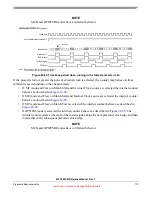
22.5.5
Global Clock Prescaler Submodule (GCP)
The GCP divides the system clock to generate a clock for the CPs of the channels. The main clock signal
is prescaled by the value defined in
according to the GPRE[0:7] bits in EMIOSMCR register.
The global prescaler is enabled by setting the GPREN bit in the EMIOSMCR register and can be stopped
at any time by clearing this bit, thereby stopping the internal counters in all the channels.
In order to ensure safe working and avoid glitches the following steps must be performed whenever any
update in the prescaling rate is desired:
1. Write 0 at GPREN bit in EMIOSMCR register, thus disabling global prescaler;
Red-line bus
time base
REDC
output
(24-bit wide)
Time Slot selector bits
SRV2 SRV1 SRV0
SRV3
Red-line bus (REDC input)
TS[00]
TS[01]
TS[02]
1. Maximum of 16 Time Slots (TS[n])
NOTES:
TS[01]
TS[00]
TS[n]
1
TS[02]
time base (REDC output)
TS[01]
TS[01]
xx
2. In this case, SRV bits were set to capture TS[01]


