background image


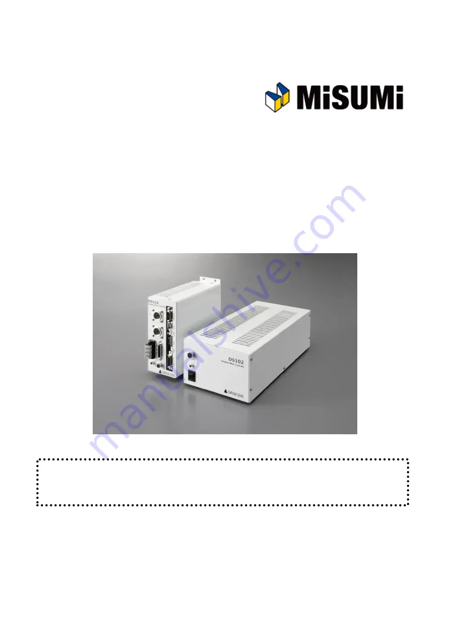
Stepping Motor Controller 

MSCTL102 Series/MSCTL112 Series Operation Manual 


Ver 1.01 (02.13.2015) 


Remarks 


MSCTL102/112 Series(MISUMI products) are same as    DS102/112 Series that are made by Suruga Seiki. 


All of DS102/112 series that are mentioned in the operation manual indicate    MSCTL102/112.   


MISUMI CO., LTD.     

SURUGA SEIKI CO., LTD.   


Summary of Contents for DS102MS

Page 1: ...eration Manual Ver 1 01 02 13 2015 Remarks MSCTL102 112 Series MISUMI products are same as DS102 112 Series that are made by Suruga Seiki All of DS102 112 series that are mentioned in the operation ma...

Page 2: ...H GENERAL 2 2 5 MOVE TO ARBITRARY COORDINATE 2 2 6 CONTROLLED OVER 3 AXES SPEC AND FUNCTION 3 1 BASIC SPEC 3 2 PART NAME AND FUNCTIONS 3 3 SETTING 63 3 4 EXTERNAL INTERFACE 64 3 4 1 LINK CONNECTION LI...

Page 3: ...ITION POS KEY 103 4 1 5 4 VERSION CONFIRMATION PARAMETER RESET 104 4 2 DS102 112 CONTROLLED SOFTWARE DSCONTROL WIN 105 4 2 1 DSCONTROL WIN START UP 105 4 2 2 PARAMETER SET UP 105 4 2 3 JOG DRIVING 107...

Page 4: ...STOMER SERVICE 158 APPENDIX 159 DIP SWITCH SET 159 DS102 EXTERNALS 160 DS112 EXTERNALS 161 CONTROL I O CABLE MODEL DS100 CNT 2 162 GENERAL I O CABLE MODEL DS100 IO 2 163 SELECTION OF A PROGRAM NUMBER...

Page 5: ...extension cable without protective earth terminal protective earth will be of no effect Cable When you unplug a power cable turn off a power switch When it supplies DS112 Series with a power supply pl...

Page 6: ...tion of the product Remodeling Please DO NOT perform the resolution of the product remodeling the unfair repair Please contact us for correct information if needed Repair Service In the case of the fo...

Page 7: ...ufacturing you can use what you want Computer PLC DC24V AC100V X Y DS112 Stepping Motor Controller DS112 Stepping Motor Controller DS102 DS112 series AC100 240V DC24V Motorized stage DS102 112 Control...

Page 8: ...C100 240V DC24V Line up products SURUGA Type MISUMI Type Input PS Type of Drive General I O DS102NR MSCTL102 AC100 240V 10 50 60Hz Normal FULL HALF DS102NR IO MSCTL102 IO Input16 Output12 DS102MS MCST...

Page 9: ...ge Y Axis Stage PLC X Y DS112 Stepping Motor Controller DS112NR Move the teaching point Switch the program drive Teaching point number selected Program number selected Start Stop DS102 112 Controlled...

Page 10: ...Actuator USB or RS 232C X axis stage Y axis stage PC General Input 16points General Output 12points DS102 Stepping Motor Controller DS102NR IO Use virtual COM port Ex VB RS 232C communication applica...

Page 11: ...xclusively for this machine Set up and example of use 2 1 Set up before use Shows flow before use DS102 DS112 MISUMI Type MSCTL102 MSCTL112 Operation check DS102 or DS112 X axis stage Y axis stage Mot...

Page 12: ...ctor for control RS232C X axis stage connector General I O Connector X Y I O CNT I O EMS SW1 LINK USB RS232C USB Connector AC Inlet Y axis stage connector I O CNT I O USB RS232C X Y TERMINAL DS102 Ste...

Page 13: ...ges D214 1 E D214 1 R MISUMI SRCB SRCB R 12 pins series stages D214 2 E D214 2 R MISUMI MSCB MSCB R D214 2 EA D214 2 RA MISUMI MS4CB MS4CB R Attached Power Cable Connect X axis motor connector to X ax...

Page 14: ...I O EMS SW1 LINK USB RS232C DS112 GND FG I O Y axis motor connector Terminal block for power General I O connector Handy terminal for connector RS232C connector USB connector I O connector for control...

Page 15: ...CD ROM to computer drive Switch on DS102 112 and wait 5 seconds Connect computer USB port and DS102 112 USB connector When computer recognize to connect DS102 112 shows following messages At the dete...

Page 16: ...Check the included this location in the search push Browse and select Win2KXP then click next Start the driver install Click the Continue Anyway when displays Hardware Installation...

Page 17: ...Click finish Display the found new hardware wizard Select No not this time and click Next Select Install from a list or specific location advanced and click Next...

Page 18: ...Check the included this location in the search push Browse and select Win2KXP then click next Start the driver install Click the Continue Anyway when displays Hardware Installation...

Page 19: ...or control software DS102 112 DSCONTROL WIN Show how to install software DS CONTROL WIN to control DS102 112 by PC Insert CD ROM of DSCONTROL WIN inside PC drive Double click on setup exe in CD ROM DS...

Page 20: ...Select folder of installation then click Next The screen shows folder selection On initial setting installation folder is Program Files SURUGA DSControlWin Click Next in case of no required folder...

Page 21: ...r from list on START MENU then click Next The drawing below appears on PC screen On initial setting Startmenu folder is DSControlWin Click Next in case of no required folder Click Next after you confi...

Page 22: ...Click YES No pop up message appears if you already select folder Installation begins Installation complete Click Finish Installing DSCONTROL WIN completed...

Page 23: ...1 4 Adjustment system parameter Shows how to set up system parameter by DSCONTROL WIN Starts DSCONTROL WIN Select Parameter setting in Action Parameter setting appears on screen Click on Tab you selle...

Page 24: ...el input direct value if we want to change initial value Select axis parameter by repeating again Click Apply Screen shows folder storing parameter Select folder and input file name then click Save Pa...

Page 25: ...Starts DSCONTROL WIN Click JOG in Action on main menu JOG dialog appears on screen Click Origin Org Home appears Click Org on X axis X stage return origin position Make sure X stage moves origin posi...

Page 26: ...X stage moves toward CW direction Stage stops when it reachs to CWLS then indicator leftside becomes RED Keep clicking on X axis X stage moves toward CCW direction Stage stops when it reachs to CCWLS...

Page 27: ...n P T_RUN means Teaching working and Program working Waiting posi 50 100 Working posi 1000 1500 Exporting Posi 2000 3000 X axis stage CPU unit I O unit Y axis stage PLC X Y DS112 Stepping Motor Contro...

Page 28: ...TEP4 Wait until exporting is done STEP5 3 Connect Connect to DS112 PC is used when setting or editing teaching point Connect USB to PC USB port Connect RS232C to PC when using RS232C Connect handy ter...

Page 29: ...hing on main menu in DSCONTROL WIN Screen below appears Push direction key on handy terminal unitl stage moves to specific positon Jog 7 Menu 8 Set 9 SPD 4 5 POS 6 1 Link 2 3 Stop 0 ESC DT100 Handy Te...

Page 30: ...Click 00 CELL on the teacing screen 00 CELL gets to be Red Click Set Current stage position as 00 is memorized to DS112 Repeat so memorize 01 as working position and 02 as exporting position to DS112...

Page 31: ...ching points memorized are saved as teaching file in PC Click Save Save As appears on screen Clcik Save after you determine Save location and File name Teaching file is saved in PC tdf is added to you...

Page 32: ...on No interference affects stage movement Click 00 CELL on teaching screen 00 CELL gets to be Red Click Go to Stage moves to teaching point 00 Waiting point Repeat and check same operation at teaching...

Page 33: ...ovement to teaching position by PLC All stages stop when making signal STOP ON Timing chart PRG TCH T_BIT5 0 P T_START Function 00 01 02 Move to wait posi Move to Target Working Move to expt posi Work...

Page 34: ...ting up Origin program at program 0 in DS112 and Origin program starts by using PLC Set 0 among P_BIT0 2 and make P T_START ON Program 0 starts CPU unit I O unit X axis stage Y axis stage PLC X Y DS11...

Page 35: ...ct Y axis stage connector to Y axis stage Connect control I O connector to I O unit in PLC On control I O P_BIT0 2 Select program P T_START Signal of movement to teaching point STOP Stop signal for al...

Page 36: ...appears on display Click Speed on command menu Speed Setup appears on display Check axis X and input speed value then click OK Command appears on the program drive screen Click Add on Program drive D...

Page 37: ...ngle Axis Drive appears on display Single Axis Drive display Mode ORG Axis X Wait until finish Enable Click OK Origin of X axis command appears on the first line Repeat for Y axis Click Add Drive comm...

Page 38: ...Click Speed Speed Setup display appears display Check Axis X and input drive speed value then click OK Speed command appears on the fourth line Repeat to set up Y axis speed...

Page 39: ...5 Writing program Writing program to DS112 Click Write Write Program appears on display Select 0 then click Transfer Program is forwarded to Program 0...

Page 40: ...am at PC program drive file Click Save on program drive display The display below appears on display Select location and file name then click Save Program is saved as Program drive file prg is automat...

Page 41: ...7 Operation check Checking movement to origin return No interference affects stage movement Click Start Start Program appears on display Select program 0 then click Start...

Page 42: ...stop when STOP button Timing chart PRG TCH P_BIT2 0 P T_START 0 X axis origin return Y axis origin return P T_RUN READY X_DRIVE Y_DRIVE Function HP X 0 0005000m Y 5 000u Parametor Axis Setting data U...

Page 43: ...on CPU unit I O unit X guide Y guide PLC X Y DS112 Stepping Motor Controller DS112 P_BIT0 2 P T_START STOP PRG TCH CNT I O CNT I O cable DS100 CNT 2 I O X sensor Y sensor In00 In01 General I O cable D...

Page 44: ...axis stage connector to Y axis stage Connect control I Oconnector to I O unit in PLC On control I O P_BIT0 2 Select program P T_START Signal of movement to program STOP Stop signal for all axes PRG TC...

Page 45: ...4 Creating program Creating the program that stopping axis in response to external sensor Starts DSCONTROL WIN Click Action Program drive on main menu Click Add Command menu appears on display...

Page 46: ...Click Speed on command menu Check Axis X and input speed value then click Drive speed value appears on the line 0 on program drive display Click Add on Command menu appears on display...

Page 47: ...isplay Single Axis Drive Mode POS Axis X Destination 50 Waiiting until finish Enable Click OK Movement command on X axis appears Repeat then input speed drive and movement command on Y axis Click Add...

Page 48: ...Axis Drive Mode STEP Axis X Diistance 0 Direction CW Wait until finish Enable Click OK Program command on X axis appears on fourth line Click Add on Program drive Drive command menu appears Click Con...

Page 49: ...nd on fourth line while State of input0 is OFF Conditional Jump command appears on fifth line on Program Command display On Conditional jump is set up Command on fourth line is repeated while State of...

Page 50: ...5 Writing Program Writing program in DS112 Click Write on Program Drive Write Program appears on display Select Program 1 then click Transfer Program is forwarded to Program 1...

Page 51: ...am in Program drive file Click Save on Program drive display Saving display of Program drive appears Confirm save location and its name then click Save Program is saved in Program drive prg is automat...

Page 52: ...7 Operation check Checking stage movement by external signal No interference affects stage movement Click Start Start Program appears on display Select 1 at Program No then click Start...

Page 53: ...s will be stopped when input the STOP signal Timing chart Move to the start position Move 10pulse to X axis CW X axis sensor Output detector Move 10pulse to Y axis CW Y axis sensor state detection PRG...

Page 54: ...the completed pressure operating signal Pressure operating Out00 In00 Press in operating Start signal Press in operating Completed signal X axis stage Y axis stage I O Actuator Out00 In00 General I O...

Page 55: ...00 X stage move to operation point MSComm1 Output AXI2 GOABS 1500 Y stage move to operation point MSComm1 Output Out00 1 Turn on the start operation signal to the actuator Do MSComm1 Output In00 Pick...

Page 56: ...positioning correction Xrv Yrv 1 Xrv Yrv X axis stage Y axis stage DS102 Stepping Motor Controller DS102 Computer Camera X Y USB RS232C or STEP1 Shooting position move to 2000 3000 STEP2 Obtained pos...

Page 57: ...Comm1 Output AXI2 SELSP 1 F1 1000 Y stage set up speed MSComm1 Output AXI1 GOABS 2000 X stage move to shooting point MSComm1 Output AXI2 GOABS 3000 Y stage move to shooting point intXrv Obtain X direc...

Page 58: ...ler DS102 1axis 2axis Computer PLC or DS102 Stepping Motor Controller DS102 1axis 2axis DS102 Stepping Motor Controller DS102 3axis 4axis DS102 Stepping Motor Controller DS102 5axis 6axis Computer PLC...

Page 59: ...origin 12style Home position 1 place for each axis Can be set up in effective area arbitrarily External COM Interface RS232C 4 800 38 400bps Dsub9pin male USB2 0 Full Low Speed only USB mini B termina...

Page 60: ...ector for EMS cancel CNT I O Connector Check the each axis status Select program operating number Start Stop Select teaching position number Start Stop I O connector Bellows 26pin half pitch I O Conne...

Page 61: ...USB ID 2bit Command response 1bit setting up EMS Connector Connector for emergency stop Normal close Included connector for EMS cancel CNT I O Connector Check status each axis select program operatin...

Page 62: ...g item 1 key 3 X axis to Cw operation Select setting item 3 key 5 Y axis to CW operation Select setting item 5 key Y axis to CCW operation Select setting item key decimal negative SPD 4 Select speed t...

Page 63: ...hole should be comes to upper or left side of units please open over 20mm spaces If cover the upper radiation space it is to be a cause of a fire and damage because of heat up inside TERMINAL DS102 St...

Page 64: ...n No Signal I O Function 1 T I O Transmitted and received data 2 T I O Transmitted and received data 3 GND Ground 4 NC Non connected 5 T I O Transmitted and received data 6 T I O Transmitted and recei...

Page 65: ...reserved 11 EMS O EMS now detecting OFF for EMS detecting On for EMS non detecting 12 P T_RUN O Program now driving or teaching point now moving 13 COM1 Common for output signal 14 P T_BIT0 I Select...

Page 66: ...P T_BIT1 P T_BIT0 EMS Reserved READY Y_ORG Y_CWLS Y_DRIVE X_ORG X_CCWLS X_CWLS T_BIT4 PRG TCH DC 24V N C COM0 STOP P T_START COM1 P T_RUN T_BIT5 0V EMS EMS EMS 1 2 E 24V 0V PS2801 4 PS2801 4 PS2801 4...

Page 67: ...START P T_RUN P T_BIT0 P T_BIT1 P T_BIT2 READY T_BIT3 T_BIT4 T_BIT5 Start On Off On Off On Off On Off On Off On Off On Off On Off On Off On Off Operating Stop PowerON 5s 4s 30ms IN OUT STOP On Off 30m...

Page 68: ...neral input11 13 In_12 I General input12 14 In_13 I General input13 15 In_14 I General input14 16 In_15 I General input15 17 COM2 I In_00 In_15 for insulation power on 18 COM3 I OUT_00 OUT_11 for insu...

Page 69: ...6 OUT_05 OUT_04 OUT_02 OUT_01 IN_12 IN_11 OUT_00 OUT_07 24V 0V TLP281 4 TLP281 4 TLP281 4 TLP281 4 TLP281 4 TLP281 4 4 7k 4 7k 4 7k 4 7k 1 5k 1 5k 1 5k 1 5k 1 5k 1 5k 1 5k 1 5k 1 5k 1 5k 4 7k 4 7k 4 7...

Page 70: ...emergency stop signal Normal close DC24V 5mA 2 EMS Common As software s interlock function please do not use as the last protect function of systems 3 4 5 Stage interface Connect the motorized stage c...

Page 71: ...case of DS102 take out 10 screws from side of cover in case of DS112 take out 6 screws from side of cover with cross screwdriver See following picture set the marked point with precision screwdriver...

Page 72: ...1 50 0 0144 B 1 80 0 009 C 1 100 0 0072 D 1 125 0 00576 E 1 200 0 0036 F 1 250 0 00288 Please set PULSE as unit setting in case of using both DATA1 and DATA2 Division number are theoretical figure Pl...

Page 73: ...first for each setting parameter Follow the below Units setting pulse m mm deg mrad Set 1 pulse displacement at the full step Basic resolution set Set the division number 1 1 1 250 pulse displacement...

Page 74: ...ixed axis Speed table No Fixed axis Speed table No Fixed axis Speed table No Fixed axis Speed table No Fixed axis Speed table No Fixed Set as above and change the each speed table 0 to 5 setting level...

Page 75: ...mpact and vibration for stages In case of under heavy load on the stages In case of operating stages at the vertical Z axis Become triangle driving at the trapezoid driving due to small distance Avoid...

Page 76: ...nd deceleration rate 0 0 Speed table Start up speed Driving speed Acceleration and deceleration rate msec msec SAcceleration and deceleration rate 0 0 Speed table Start up speed Driving speed Accelera...

Page 77: ...the CW Detect the CCW side edge of CWLS signal 81 Type After operated type1 detect CCW side edge of TIMING signal 82 Type After operated type2 detect CW side edge of TIMING signal 82 Type After opera...

Page 78: ...d speed speed SD Start position LD Start position point JD Sensor is turned OFF when the point a is detected Near origin detection process Origin detection process point a Start position speed speed s...

Page 79: ...is turned OFF when the point a is detected Near origin detection process Origin detection process point a Start position speed speed speed speed SD Sensor is turned OFF when the point a is detected L...

Page 80: ...detection process JD JD Solid line shows emergency stop setting Dot line shows slowdown stop setting Type CW side edge a point of ORG signal is detected in CW direction point Origin detection process...

Page 81: ...speed speed SD speed JD Solid line shows emergency stop setting Dot line shows slowdown stop setting Type CCW side edge a point of CWLS signal is detected in CW direction point Start position speed s...

Page 82: ...ocess Type After the Type3 is performed CCW side edge of TIMING signal is detected Type After the Type4 is performed CW side edge of TIMING signal is detected Type After the Type5 is performed CCW sid...

Page 83: ...iving Communication command GOLineI _X Y Z U V W or CW specified direction CCW specified direction Distance PULSe setted Unit is as case of current time No driving axis is avoided example GOLineI _X Z...

Page 84: ...editor display on DSCONTROL WIN then transfer writing Refer details as shown bellows Example teaching function 2 2 1paragraph Operated by controlled I O CNT I O paragraph Operated by handy terminal p...

Page 85: ...JOG key Axis Display axis that available controlled No Link XY Link Connecting 2units XY ZU Link Connecting 3units XY ZU VW Code Display unit at the current point No display distance Current point Di...

Page 86: ...Enter TCH_MOV Move teaching point TCH_SET Return teaching point TCH_DEL Delete teaching point TCH_EDT Edit teaching point IN General Input monitor OUT General output set up PRM Parameter set up 1 Pul...

Page 87: ...key Y U W axis drive to CW key Y U W axis drive to CCW 4 1 3 2 Uniform pulse driving mode STP Step Mode Select STP display as bellows press any key start to drive uniform pulse in each parameter key X...

Page 88: ...ey X Z V axis return to origin key Y U W axis return to origin STOP key Stop all axes Press shortcut key Set key display Set up origin return type Return to origin return mode screen with Set key 4 1...

Page 89: ...sition Set up home position Origin Type Set up origin return type Current Down Set up current down Limit Sensor Set up limit sensor logic Origin Set up origin sensor logic Near Origin Set up nearby or...

Page 90: ...driving position at absolute position driving ABS Mode Display as below with Pulse ABS Select setting axis with key Return to parameter select screen with ESC key After axis selected press Enter key d...

Page 91: ...elect screen if press ESC during select the Speed Table or setting item After moved by arrow key press Enter key and then change to Possible to input with numeric keypad Displayed in continuous pressi...

Page 92: ...rized stage Input setting data with numeric keypad After input finished press Enter key return to setting item select screen DR Set up the division number of motorized driver with key Normal driver FU...

Page 93: ...L L Set up the coodinate CW CCW direction Can be changed with numeric keypad Press Enter key after finished input return to setting item select screen Return to selection screen of setting item with E...

Page 94: ...finished press Enter key be moved the cursor on left lateral and input any other axis During input the setting data press ESC key might be return to select the setting axis without input setting data...

Page 95: ...gin Sensor Logic Setting Set up each axis Origin Sensor Logic Setting When select the Origin to be Origin Sensor Logic setting screen Display the cursor on left lateral of setting axis Move cursor to...

Page 96: ...rive Direction Motor Driving Direction Set up each axis Motor Driving Direction Setting When select the Driving Direction to be Motor Driving Direction setting screen Display the cursor on left latera...

Page 97: ...etting at Origin Return Set up each axis Count Zero Reset Setting When select the Zero Reset to be Count Zero Reset setting screen Display the cursor on left lateral of setting axis Move cursor to the...

Page 98: ...cted program press ENTER key display R If press STOP ESCkey during the drive Program might be stop Return to program driving mode selection screen during press STOP ESCkey at off line STEP mode select...

Page 99: ...h key Display the teaching point what you want pressENTER key Press ENTER key at this screen start to move to teaching point Return to teaching point number selection screen during press STOP ESC key...

Page 100: ...STP Change the teaching point with key Counted up and down continuously pressed over 1sec Press ENTER key with displaying teaching number then jump to following screen It is possible to drive STEP wi...

Page 101: ...en display No Data Return to teaching mode selection screen when press ESC key EDT Teaching point edit Select EDT shows as bellows Return to teaching mode selection screen when press ESC key Use key a...

Page 102: ...31 Link No 2 InP2 In32 47 Press ESC key return to menu selection screen 4 1 4 5 General output control OUT Control general I O output port Out00 35 Select OUT display as bellows Move cursor with key m...

Page 103: ...axis Link key Press Link key at the all axis display screen included parameter setting screen selection axis change X ZU VW XY Can be changed displaying axis during driving 4 1 5 3 Changes current po...

Page 104: ...off and no Remote Mode Also return to before shipping condition each parameter setting Hold STOP key and press Enter key the controller and terminal version displays as bellows Hold STOP key and pres...

Page 105: ...an be started DSCONTROL WIN from Windows start menu Please check the power and communication cable when shows below message Start up DSCONTROL WIN when function normally Please power off this machine...

Page 106: ...ge model number you use among stage list Selecting stage model number its Initial value of stage appears When need different value input any value you want directly iv Repeat select any axis and value...

Page 107: ...click sets up limit of software Yellow Detection Limited detection of CCW direction Green Non detection Red Detection Double click sets up limit of software Yellow Detection Display set value of step...

Page 108: ...vement position double click input movement position directly After set up any value and position click GO so stage moves to position you set up Click 0 so stage move to 0 position Origin Click Orogin...

Page 109: ...ow appears Input speed value you like then click OK Speed value should be within Max speed parameter can set up To change current position value to optional value Double click so screen below appears...

Page 110: ...ng point 6 axes During movement even 1axis reaches mechanical or soft limit all axis stop Read Read and display all of teaching point 64points memorized inside DS102 or 112 DS PC Write Forward all of...

Page 111: ...eaching points memorized in DS102 or 112 i Click Read to read and display memorized 64 teaching points inside DS ii Click Export to forward displayed 64 teaching points to PC To forward Teching points...

Page 112: ...Save program displayed screen into PC Do not forward program to DS Add Add program drive command to last line in program Insert Insert program drive command into program Delete Delete 1line of progra...

Page 113: ...ears on screen Making program by programming following command Speed setup Setting up each axis speed Speed should be within parameter maximum speed Position setup Setting up or changing current posit...

Page 114: ...l drive is done please select enable at wait until finish Interpolation Drive Implement interpolation Drive Absolute value of double axes Select axis destination and click disable at wait until finish...

Page 115: ...lly Conditional jump With monitoring general input condition jump to appointed line Repeat Repeat same movement until 999 999 times Wair Do not go forward during time you set up Maximum time is 999 99...

Page 116: ...een Sample When program is done click Writing Select program then click Transfer so program is forwarded to DS iv Click Save to save program in PC Recommended v When program is done check its operatio...

Page 117: ...o displayed program is saved into PC To transfer program data saved inside PC to DS i Click Open to display program data inside PC ii Click Write Select program No and click Transfer so program is tra...

Page 118: ...put of general output can be performed i Main menu Action monitor then monitor display appears Input White OFF Green ON Output Check to output ii On linked click Next Port to see another linked monito...

Page 119: ...cable Never connect to cable in case of power on Must be risk of breakage RS232C Connector XM2C 0942 132L Omron products Dsub9P male Pin Number Name Function Not connected Received data input Send da...

Page 120: ...ID is control number Memorized product ID on ROM USB driver works with plug and play after recognized vendor ID and product ID USB hub connected Controlled multi axis In case of controlled stage that...

Page 121: ...om port number and USB ID send to SURUGA SEIKI DS102 USB Serial Port COM USBID then return USB ID each 0 3 can be confirmed COM port number and USB ID relation Continuing to fix until delete the drive...

Page 122: ...ult ON OFF 1 OFF ON 2 ON ON 3 Setting OFF before shipping 4 3 3 Delimiter Delimiter comes to the end of the communication command and response data Interface Delimiter fixed In operation of command re...

Page 123: ...ol command Data setting command Type Command Function Data Default Remarks Program driving WRITE Write in flash memory Wait over 130ms after send RST Reset of all parameter Wait over 5s after send Axi...

Page 124: ...ed due to driver PULSe_ PULS_ Stable pulse distance setting 0 99999999 1 Data range must be changed due to driver PULSeA_ PULSA_ Absolute driving coordinate value setting 99999999 99999999 9 9999999 9...

Page 125: ...origin input logic setting 0 B N C 1 A N O 0 1 0 MEMorySWitch4_ MEMSW4_ Memory switch 4 setting Countdown setting 0 Countdown controlled 1 Canceled count down control 0 1 0 MEMorySWitch5_ MEMSW5_ Memo...

Page 126: ...100 0 Lspeed5_ L5_ Start up speed Lspeed5 setting Unit pps 1 9999 100 Fspeed5_ F5_ Drive speed Fspeed5 setting Unit pps 1 999999 2000 Rate5_ R5_ Acceleratin and deceleration Rate5 setting Unit msec 1...

Page 127: ...CCWJ GOABSolute_ GOABS_ Absolute position drive 99999999 99999999 9 9999999 9 9999999 Data range must be changed due to point position GOTeaCH_ GOTCH_ Move teaching point 0 63 Teaching point number 0...

Page 128: ...nus U U axis specified to plus U U axis specified to minus V V axis specified to plus V V axis specified to minus W W axis specified to plus W W axis specified to minus X X Y Y Z Z U U V V W W Relativ...

Page 129: ...1 2 Only MS driver effective HOMEPosition HOMEP Home position request 99999999 99999999 9 9999999 9 9999999 Data range must be changed due to point position POSition POS Current position request 9999...

Page 130: ...C 1 A point N O 0 1 MEMorySWitch2 MEMSW2 Request Memory switch 2 Origin sensor input logic setting 0 B point N C 1 A point N O 0 1 MEMorySWitch3 MEMSW3 Request Memoryswitch 3 Near origin input logic...

Page 131: ...etting Unit 0 100 Lspeed3 L3 Request start up Lspeed3 setting Unit pps 1 9999 Fspeed3 F3 Request drive speed Fspeed3 setting Unit pps 1 999999 Rate3 R3 Request acceleration and deceleration Rate3 sett...

Page 132: ...cceleration and deceleration Rate9 setting Unit msec 1 9999 Srate9 S9 Request S rate Srate9 setting Unit 0 100 Status request COURSE Motion direction status 0 Motion stop to CW 1 Motion stop to CCW 0...

Page 133: ...st Bit1 Possible select axis Bit2 Driver type Bit3 reserved Bit4 reserved Bit5 reserved Bit6 reserved Bit7 reserved Bit8 reserved 0 3 CONTrolAxis CONTA Number of controlling axis status 2 2 axes 4 4 a...

Page 134: ...l bits no output 4095 all bits output 0 4095 Request each board ID0 2 Out 12 points at the 1 command Version request DS102VER Controller version request command DS102_0 00 Version 0 00 DS102_9 99 Vers...

Page 135: ...ng command and driving command colon is necessary when connect max 100 letter Orders of connection have to begin with Axis Specification Command Parameter Setting Command Driving Command Please select...

Page 136: ...a Command to set CCW side Software Limit of each axis Setting data is In case of continuing 0 after the decimal point can be skippable Ex In case of data is not a multiple of the travel distance per p...

Page 137: ...is Multiple Data Travel distance per pulse Omit the figures after the decimal point of Multiple Data Travel distance per pulse Multiple Travel distance per pulse Standard resolution of motorized stage...

Page 138: ...river correspondingly change travel distance per pulse which may become not a multiple of the following parameters Setting of Constant Step Pulse Setting of Soft Limit Setting of Home Position Current...

Page 139: ...t Origin Return Type 0 Origin Return Type 7 Origin Return Type 1 Origin Return Type 8 Origin Return Type 2 Origin Return Type 9 Origin Return Type 3 Origin Return Type 10 Origin Return Type 4 Origin R...

Page 140: ...t 4 3 5 4 Speed Table Setting Command This command conducts setting of Start up Velocity L Driving Speed F and Acceleration Deceleration Rate R S Acceleration Deceleration Rate S of Speed Table No 0 9...

Page 141: ...off for over 130 msec after send write command Can keep setting value from Handy Terminal and Control Software DSCONTROL WIN 2 RST Command to reset the all parameter Do not power off for 5sec after s...

Page 142: ...le Data Travel distance per pulse Multiple Travel distance per pulse Standard resolution of motorized stage Dividing number of driver 3 Data Go Teaching Point Move Command Data is Teaching point Numbe...

Page 143: ...ection command is available Use colon to connect commands Orders of connection have to begin with Axis Selection Command Parameter Setting Request Command Parameter Setting Request Command is configur...

Page 144: ...setting In the process of setting In the process of setting 6 DATA Command to request for setting to dividing number switching with Microstep driver No work at Normal driver Response Data Content 1 In...

Page 145: ...isdataunset 4 Uaxisdata 99999999 99999999 9 9999999 9 9999999 Uaxisdataunset 5 Vaxisdata 99999999 99999999 9 9999999 9 9999999 Vaxisdataunset 6 Waxisdata 99999999 99999999 9 9999999 9 9999999 Waxisdat...

Page 146: ...en 3 Command to request for setting of Memory SW 2 Origin Sensor Input Logic for each axis Response Data Content Selecting B of Origin Sensor Input Logic Normal Close Selecting A of Origin Sensor Inpu...

Page 147: ...on and Deceleration Rate S is a choice of the number of requested Speed Table will be in Response Data is 0 100 UNIT is 4 3 5 11 Status Request Command This command request for status on motion direct...

Page 148: ...ion Response Data Content Setting of Software Limit in the CCW direction is Non effective Setting of Software Limit in the CCW direction is Effective This is the same as Bit6 of StatusBinary2 See 13 4...

Page 149: ...eturn is not in process Origin Return has been completed and Mechanical Origin has been detected At halt This is the same as Bit5 of Status Binary1 See 12 10 Status Request Command for availability of...

Page 150: ...ion Detection 1 Detecting Home Position 0 Not yet detecting Home Position Bit 7 In Motion At Halt 1 In Motion 0 At Halt Bit 8 Program Driving Stopping 1 Program driving 0 Program under suspension 13 S...

Page 151: ...Data is 16 Status Request Command for all axes in motion Response Data is Response Data 1 Bit 8 Bit 7 Bit 6 Bit 5 Bit 4 Bit 3 Bit 2 Bit 1 Waxis in motion Vaxis in motion Uaxis in motion Zaxis in moti...

Page 152: ...OFF 65535 All of 16 points ON 3 OUT Data Control Command of General Output 0 35 Set 1 bit 00 35 Setting Data Content Output OFF 1 Output ON 4 OUTP Data Control Command of General Output Request Output...

Page 153: ...atch the Input Port Status IJMP_ 00 47 0 or 1 0 99 Ex IJMP_05 1 28 When Input Port No 05 is ON jump to 28 th Line If OFF jump to next line LoopS_ Loop Start Command 1 999 999 times repeat till LoopE L...

Page 154: ...en in a flash memory is answered that writing is completed A part of program cannot be changed Procedure example of Program Upload DELPRG 0 SETPRG 0 0 AXI1 PULS_1000 SETPRG 0 1 LoopS_10 SETPRG 0 2 AXI...

Page 155: ...ction program sequence motion or STEP Start a selection program step driving Program Number Request Command Request a Program Number during selecting Response Data is 0 7 Program Number Start Command...

Page 156: ...Emergency detecting Start Driving Command when input the emergency signal E20 Command rule error Error of command documents E21 Error of unsent delimiter No delimiter CR or incorrect E22 Setting Range...

Page 157: ...r cable Recheck connecting is correct A motor is not spin On emergency Recheck emergency stop is ON Current down function is OFF for NR type Switch ON current down function for NR type No match betwee...

Page 158: ...ure Damage or injury due to not following the proper procedures as indicated in the instruction manuals not adhering to the caution warnings as indicated in the instruction manuals Repair Service Plea...

Page 159: ...800bps ON OFF 9 600bps OFF ON 19 200bps ON ON 38 400bps Default Link Number 3 4 Link Number OFF OFF 0 Default ON OFF 1 OFF ON 2 ON ON USB ID 5 6 USB ID OFF OFF 0 Default ON OFF 1 OFF ON 2 ON ON 3 Com...

Page 160: ...160 DS102 Externals 139 2 300 TERMINAL DS102 Stepping Motor Controller X Y I O CNT I O EMS SW1 LINK USB RS232C 89 6 6 10 4 55 17 8 154 134 20 260 94 6 21 7 97 6...

Page 161: ...161 DS112 Externals 155 70 X Y TERMINAL POWER 24V CNT I O EMS SW1 LINK USB RS232C DS112 Stepping Motor Controller GND FG I O 177 4 11 3 1 6 3 7 170 10 4 5 4 5 50 66 165 7 0 8 22 41 2 151...

Page 162: ...y Black3 White Black3 Orange Red1 Gray Red1 White Red1 Yellow Red1 Pink Red1 Orange Red2 Gray Red2 White Red2 1 2 3 4 5 6 7 8 9 10 11 12 13 14 15 16 17 18 19 20 21 22 23 24 25 26 X_DRIVE X_CWLS X_CCWL...

Page 163: ...ray Black3 White Black3 Yellow Black3 Pink Black3 Orange Black4 Gray Black4 White Black4 Orange Red1 Gray Red1 White Red1 Yellow Red1 Pink Red1 Orange Red2 Gray Red2 White Red2 Yellow Red2 Pink Red2 O...

Page 164: ...OFF OFF OFF ON ON ON ON ON ON ON ON P T_BIT4 24 16 ON ON ON ON ON ON ON ON ON ON ON ON ON ON ON ON P T_BIT5 25 32 OFF OFF OFF OFF OFF OFF OFF OFF OFF OFF OFF OFF OFF OFF OFF OFF 32 33 34 35 36 37 38...

Page 165: ...First edition Ver1 00 1 05 Ver1 01 Ver1 01 1 03 Ver1 01 02 13 2015 P59 Correction of DT100 outside dimension P74 Correction of S rate P77 Addition of ORG type KXT KRE KHE P81 Correction of stop proce...

Page 166: ...166...

Reviews: