


MPC563XM Reference Manual, Rev. 1
Freescale Semiconductor
697
Preliminary—Subject to Change Without Notice
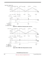
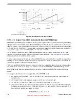
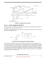
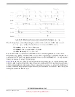
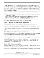
Figure 22-67. OPWMB Mode with Active Output Disable
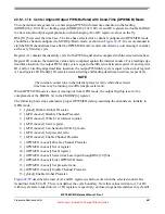
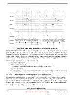
shows a waveform changing from 100% to 0% duty cycle. EDPOL in this case is zero. In
this example B1 is programmed to the same value as the period of the external selected time base.
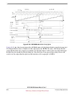
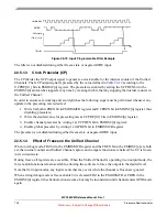
Figure 22-68. OPWMB Mode from 100% to 0% Duty Cycle
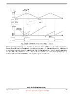
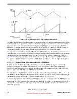
if B1 is set to a value lower than $8 it is not possible to achieve 0% duty cycle by only
changing A1 register value. Since B1 matches have precedence over A1 matches the output pin transitions
to the opposite of EDPOL bit at B1 match. Note also that if B1 is set to $9, for instance, B1 match does
not occur, thus a 0% duty cycle signal is generated.
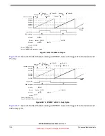
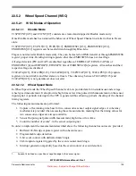
22.5.1.1.19
Output Pulse Width Modulation with Trigger (OPWMT) Mode
OPWMT mode (MODE[0:6]=0100110) is intended to support the generation of Pulse Width Modulation
signals where the period is not modified while the signal is being output, but where the duty cycle will be
varied and must not create glitches. The mode is intended to be used in conjunction with other channels
EDPOL = 0
cycle n
cycle n+1
cycle n+2
A1 value
B1 value
B2 value
$000008
$000002
$000006
$000008
$000001
Selected
$000004
$000006
MODE
[6]
= 1
A2 value
$000002
$000004
$000006
$000002
$000004
$000006
$000008
$000006
Output pin
write to B2
write to A2
write to A2
Match A1
Match A1
Match B1
Match B1
Match B1
due to B1 match cycle n-1
FLAG set event
Output Disable
Counter Bus
FLAG pin/register
FLAG clear
$000008
$000007
$000006
$000005
$000004
$000003
$000002
$000001
$000000
0%
100%
Selected
EDPOL = 0
A1 value
B1 value
Output pin
$000008
Prescaler = 1
cycle 1
cycle 2
cycle 3
cycle 4
cycle 5
cycle 6
cycle 7
cycle 8
cycle 9
counter bus
$000007
$000006
$000005
$000004
$000003
$000002
$000001
$000000
A2 value


