


MPC563XM Reference Manual, Rev. 1
1284
Freescale Semiconductor
Preliminary—Subject to Change Without Notice
Mode or in Freeze Mode. Exceptions are the BOFF_MSK, ERR_MSK, TWRN_MSK, RWRN_MSK and
BOFF_REC bits, that can be accessed at any time.
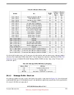
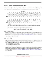
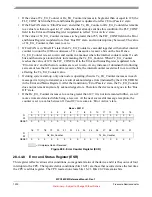
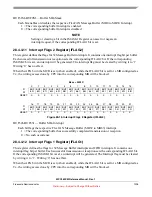
Figure 28-6. Control Register (CTRL)
PRESDIV — Prescaler Division Factor
This 8-bit field defines the ratio between the CPI clock frequency and the Serial Clock (Sclock)
frequency. The Sclock period defines the time quantum of the CAN protocol. For the reset value, the
Sclock frequency is equal to the CPI clock frequency. The Maximum value of this register is $FF, that
gives a minimum Sclock frequency equal to the CPI clock frequency divided by 256. For more
information refer to
Section 28.5.8.4, “Protocol Timing.”
Sclock frequency = CPI clock frequency / (P 1)
RJW — Resync Jump Width
This 2-bit field defines the maximum number of time quanta
1
that a bit time can be changed by one
re-synchronization. The valid programmable values are 0
–
3
.
Resync Jump Width = RJW + 1.
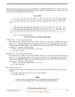
PSEG1 — Phase Segment 1
This 3-bit field defines the length of Phase Buffer Segment 1 in the bit time. The valid programmable
values are 0
–
7
.
Phase Buffer Segment 1 = (PSEG1 + 1) x Time-Quanta.
PSEG2 — Phase Segment 2
This 3-bit field defines the length of Phase Buffer Segment 2 in the bit time. The valid programmable
values are 1
–
7
.
Phase Buffer Segment 2 = (PSEG2 + 1) x Time-Quanta.
Base + $0004
0
1
2
3
4
5
6
7
8
9
10
11
12
13
14
15
R
PRESDIV
RJW
PSEG1
PSEG2
W
RE-
SET:
0
0
0
0
0
0
0
0
0
0
0
0
0
0
0
0
16
17
18
19
20
21
22
23
24
25
26
27
28
29
30
31
R
BOFF
_MSK
ERR_
MSK
CLK_
SRC
LPB
TWR
N_MS
K
RWR
N_MS
K
0
0
SMP
BOFF
_REC
TSYN
LBUF LOM
PROPSEG
W
RE-
SET:
0
0
0
0
0
0
0
0
0
0
0
0
0
0
0
0
= Unimplemented or Reserved
1.
One time quantum is equal to the Sclock period.


