


MPC563XM Reference Manual, Rev. 1
Freescale Semiconductor
673
Preliminary—Subject to Change Without Notice
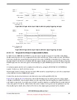
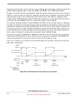
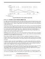
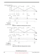
Note that EMIOSCNT[n] is stable only outside the time window defined from A1 to B1 matches,
otherwise its contents reflects a count in progress and not the final value. Alternatively to EMIOSCNT
register A2 returns the latest available measurement. Since this register is updated only at comparator B
matches it always contains stable and up-to-date data. In this mode this register is accessible through the
alternate register address EMIOSALTA[n].
shows how the Unified Channel can be used to accumulate high time.
Figure 22-43. Windowed Programmable Time Accumulation example
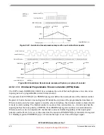
22.5.1.1.11
Modulus Counter (MC) Mode
The MC mode can be used to provide a time base for a counter bus or as a general purpose timer.
MODE[6] bit selects internal or external clock source when cleared or set, respectively. When external
clock is selected, the input signal pin is used as the source and the triggering polarity edge is selected by
the EDPOL and EDSEL in the EMIOSC[n] register.
The internal counter counts up from the current value until it matches the value in register A1. Register B1
is cleared and is not accessible to the MCU. MODE[4] bit selects up mode or up/down mode, when cleared
or set, respectivelly.
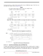
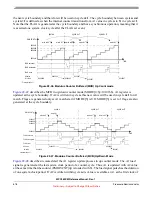
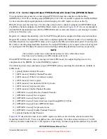
When in up count mode, a match between the internal counter and register A1 sets the FLAG and clears
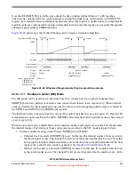
the internal counter. The timing of those events varies according to the MC mode setup as follows:
•
Internal counter clearing on match start (MODE[0:6]=001000b)
— External clock is selected if MODE[6] is set. In this case the internal counter clears as soon as
the match signal occurs. The channel FLAG is set at the same time the match occurs. Note that
by having the internal counter cleared as soon as the match occurs and incremented at the next
input event a shorter zero count is generated. See
.
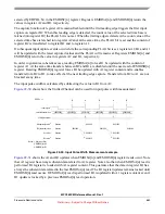
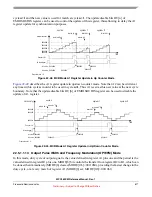
— Internal clock source is selected if MODE[6] is cleared. In this case the counter clears as soon
as the match signal occurs. The channel FLAG is set at the same time the match occurs. At the
$FFFFFF
$000000
Time accumulator (EMIOSCNT)
B1 Match
selected counter bus
$001500
A1 value
2
$001500
$000100 $000100
input signal
1
$004200
$003000
B1 Match
B1 value
3
$001500
$004200
$000100
A1 Match
A1 B1 write
A1 Match
A1 B1 write
$003000
$004200
FLAG pin/register
Notes: 1. After the input filter
EDPOL = 1
2. EMIOSA[n] = A1
3. EMIOSB[n] = B1
$003000
A2 value
4
EMIOSCNT[n]
EMIOSCNT[n]
4. EMIOSALTA[n] = A2
A2
A2


