


MPC563XM Reference Manual, Rev. 1
940
Freescale Semiconductor
Preliminary—Subject to Change Without Notice
This example uses a relatively simple system in order to illustrate the basic principles of second-pass
analysis. For a more complex example of second-pass analysis, refer to Multiphase Motor Commutation
TPU Function (COMM)(TPUPN09/ D).
23.5.5.5.1
Second-Pass Analysis Guidelines
Rather than use a fixed formula, a second-pass analysis relies on the application of the following
guidelines.
1. The first-pass analysis makes the assumption that all channels in the system are continually
requesting service. For many systems this is an unrealistic assumption. For example, if TCR1 is
counting at a rate of 2 MHz (500 ns per count) and a channel is running the DIO function with a
match rate of 20,000 TCR1 counts, the DIO will request service every 10 ms (20,000 * 500 ns =
10,000,000 ns or 10 ms). It is therefore unrealistic to assume that the channel running this DIO
function is continuously requesting service. Figure out a realistic service request rate for each
channel. Time slots can then be mapped to each channel at the real rate of request.
2. If a function is active during system initialization but not during the high-speed running mode of
the system, then that system does not need to be included in the high-speed worst-case latency
calculations.
3. Use a realistic SPRAM collision rate.
4. Be careful when assigning functions priority levels and channel numbers. Decide which function
or functions will be most difficult to make perform at the desired level. Assign those channels high
priority and low channel numbers. Try different priority and channel assignments to see how it
affects the system.
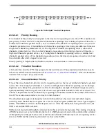
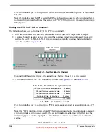
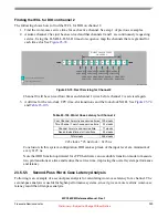
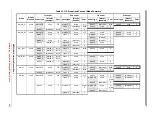
5. The seven-slot sequence of || H | M | H | L | H | M | H || is asymmetrical when put back-to-back with
other seven-slot sequences. Note that in the following sequence there are two high-priority slots
next to each other:
|| H | M | H | L | H | M | H |||| H | M | H | L | H | M | H ||
6. Make sure that when mapping out channels to the sequence, you choose a worst-case slot to start
the mapping. For example, when estimating WCL for a high-priority channel, do not start the
mapping in the last high-priority slot in a seven-slot sequence, as that is a best case for a
high-priority channel since another high-priority time slot is next.
7. Instead of always using the longest thread in the function as the worst-case thread, evaluate the
threads in the function that will be used in the system and use the appropriate worst-case threads.
For example, in the preceding example of first-pass analysis, the PWM was shown to be able to
achieve a high time and low time of 2475 ns under worst-case conditions. This was derived using
the longest PWM thread of 24 CPU clocks. This longest thread is actually thread 2, the thread that
is entered after the pin has just gone high. Thread 3, the thread that is entered after the pin has just
gone low, requires only 2 CPU clocks. Therefore, in the first-pass example, the high time was
correctly derived, but the low time is actually shorter than was estimated.
23.5.5.5.2
Second-Pass Analysis Example
This example requires three 50% PWM waveforms: one 5 kHz (200 ms/period) and two 50 kHz (20
ms/period), each running DC motors. (Remember that the PWM function requests service from the eTPU


