


MPC563XM Reference Manual, Rev. 1
1258
Freescale Semiconductor
Preliminary—Subject to Change Without Notice
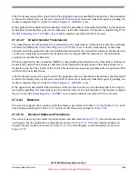
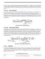
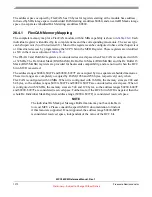
Figure 27-46. Standard LIN frame format
27.4.6.2.2
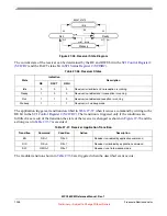
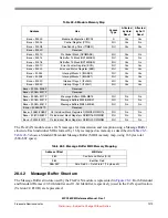
CRC Enhanced LIN frames
The CRC Enhanced LIN frames shown in
contain two additional CRC byte fields. These
fields are located between the last data field and the Checksum field. The value of the CRC is calculated
on the same byte fields as the Checksum is calculated on. The polynom used for the CRC calculation is
defined by
LIN CRC Polynomial Register 1 (LINCRCP1)
. The eSCI module generates the CRC fields for TX frames and checks the CRC fields for
RX frames if the CRC bit in the
was written with a value of 1.
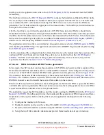
Figure 27-47. CRC Enhanced LIN frame format
The CRC Enhanced LIN frames are not part of the LIN standard.
27.4.6.3
LIN TX Frame generation
The eSCI module supports two modes of LIN TX Frame generation. In the application controlled mode,
the application provides the required frame configuration and frame data by subsequent write accesses to
the
. In the DMA generation mode, the DMA controller provides the required
frame configuration and frame data in response to DMA requests generated by the eSCI module.
27.4.6.3.1
Application Controlled LIN TX Frame generation
In this mode, the application requests and controls the generation of an LIN TX Frame by subsequent write
access to the
. To determine when to write to the
,
the application can use the TXRDY flag in the
LIN Status Register 1 (LINSTAT1)
. If this flag is set, the
and should clear the TXRDY immediately.
contains the Identifier and Identifier Parity fields.
The second byte written defines the number of data bytes to be transmitted. The third write access defines
the CRC and checksum generation. The TD bit has to set to 1 to invoke the TX frame generation. The TO
field bits must be set to 0.
After the third byte was written the generation of a LIN TX frame is started. Firstly, a break field is
transmitted, then the synch field and the protected identifier field.
All subsequent write accesses provide data bytes, and a data byte field will be transmitted as soon as the
data are available. After the last data byte, defined by the value written to the LEN field, was send out, the
configured CRC and checksum fields will be send out.
After the transmission of the last byte field of the frame, the write counter for the
is reset and the TXRDY flag is set.
Break
Synch
Identifier
Data 1
Data 2
Data N
Checksum
Break
Synch
Identifier
Data 1
Data 2
Data N
Checksum
CRC1
CRC2


