


MPC563XM Reference Manual, Rev. 1
404
Freescale Semiconductor
Preliminary—Subject to Change Without Notice
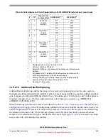
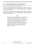
13.6.7
Address/Data Multiplexing Connection Examples
shows an example of a typical bus connection with 32-bit bus implementation, where all
peripherals have A/D multiplexing with a 32-bit bus implementation.
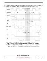
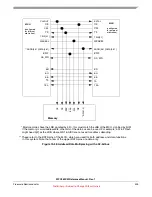
shows an example of a typical bus connection with 16-bit bus implementation, where all
peripherals have A/D multiplexing with a 16-bit bus and 8 additional address bits that are non-multiplexed.
In this mode the EBI_MCR[DBM] must be set (1), and the EBI_BRx[PS] (or EBI_CAL_BRx[PS]) must
also be set (1) for the 16-bit memory.
NOTE
For systems using A/D multiplexing in 16-bit mode, it is recommended that
the user set the D16_31 bit in the EBI_MCR, so that ADDR[16:31]
functions are muxed onto the DATA[16:31] pins. This allows one MCU
(that may be sold in 16-bit and 32-bit data bus packages) to be used in a
16-bit A/D muxed mode on the 16-bit package version, and then move up
to 32-bit A/D muxed mode on a 32-bit package version, while still
maintaining the same multiplexed ADDR[16:31] functions on the
DATA[16:31] pins. This also allows one MCU to run with both 16-bit and
32-bit A/D muxed devices at the same time. Neither of these cases are
possible if a value of 0 for EBI_MCR[D16_31] bit is used (because
ADDR[0:15] will be muxed onto DATA[16:31] for 32-bit mode,
DATA[0:15] for 16-bit mode).


