


MPC563XM Reference Manual, Rev. 1
430
Freescale Semiconductor
Preliminary—Subject to Change Without Notice
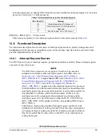
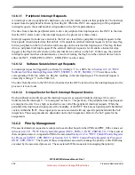
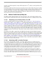
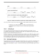
Figure 14-13. Software Vector Mode Handshaking Timing Diagram
14.6.3.2
Hardware Vector Mode Handshaking
A timing diagram of the interrupt request and acknowledge handshaking in hardware vector mode, along
with the handshaking near the end of the interrupt exception handler, is shown in
software vector mode, the INTC examines the peripheral and software setable interrupt requests, and when
it finds an asserted one with a higher priority than PRI in the associated INTC_CPR_PRC0 or
INTC_CPR_PRC1, it asserts the interrupt request to the associated processor. The INTVEC field in the
associated INTC_IACKR_PRC0 or INTC_IACKR_PRC1 is updated with the preempting peripheral or
software setable interrupt request’s vector when the interrupt request to the processor is asserted. The
INTVEC field retains that value until the next time the interrupt request to the associated processor is
asserted. In addition, the value of the interrupt vector to the associated processor matches the value of the
INTVEC field in the associated INTC_IACKR_PRC0 or INTC_IACKR_PRC1. The rest of the
handshaking is described in
Section 14.3.1.2, “Hardware Vector Mode
The handshaking near the end of the interrupt exception handler, that is the writing to the associated
INTC_EOIR_PRC0 or INTC_EOIR_PRC1, is the same as in software vector mode. Refer to
Section 14.6.3.1.2, “End of Interrupt Exception Handler
”.
0
1
0
clock
interrupt request to processor
hardware vector enable
interrupt vector
interrupt acknowledge
read INTC_IACKR_PRC
x
write INTC_EOIR_PRC
x
INTVEC in INTC_IACKR_PRC
x
PRI in INTC_CPR_PRC
x
peripheral interrupt request 100
0
108
0


