


MPC563XM Reference Manual, Rev. 1
Freescale Semiconductor
1177
Preliminary—Subject to Change Without Notice
In SPI Configuration, Master Mode transfer attributes are controlled by the SPI command in the current
TX FIFO entry. The CTAS field in the SPI command selects which of the eight DSPI_CTAR registers will
be used to set the transfer attributes. Transfer attribute control is on a frame by frame basis. See
Section 26.5.3, “Serial Peripheral Interface (SPI) Configuration
,” for more details.
In DSI Configuration, Master Mode transfer attributes are controlled by the DSPI DSI Configuration
Register (DSPI_DSICR). The DSISCTAS field in the DSPI_DSICR selects which of the DSPI_CTAR
registers will be used to set the transfer attributes. Transfer attributes are set up during initialization and
should not be changed between frames. See
Section 26.5.4, “Deserial Serial Interface (DSI)
In CSI Configuration, the DSI data is transferred using DSI Configuration transfer attributes and SPI data
is transferred using the SPI Configuration transfer attributes. In order for the bus slave to distinguish
between DSI and SPI frames, the transfer attributes for the two types of frames must utilize different
Peripheral Chip Select signals. See
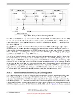
Section 26.5.5, “Combined Serial Interface (CSI) Configuration
details.
26.5.1.2
Slave Mode
In Slave Mode the DSPI responds to transfers initiated by a SPI master. The DSPI operates as bus slave
when the MSTR bit in the DSPI_MCR register is negated. The DSPI slave is selected by a bus master by
having the slave’s SS asserted. In Slave Mode the SCK is provided by the bus master. All transfer attributes
are controlled by the bus master but clock polarity, clock phase and numbers of bits to transfer must still
be configured in the DSPI slave for proper communications.
The SPI and DSI configurations are valid in Slave Mode. In SPI Slave Mode the slave transfer attributes
are set in the DSPI_CTAR0. In DSI Slave Mode the slave transfer attributes are set in the DSPI_CTAR1.
In both SPI and DSI configurations the DSPI in Slave Mode transfers data MSB first. The LSBFE field of
the associated CTAR is ignored.
26.5.1.3
Module Disable Mode
The Module Disable Mode is used for MCU power management. The clock to the non-memory mapped
logic in the DSPI can be stopped while in Module Disable Mode.The DSPI enters the Module Disable
Mode when the MDIS bit in DSPI_MCR is set or when a request for the DSPI to enter Doze Mode is
asserted by an external controller while the DOZE bit in the DSPI_MCR is asserted. Logic external to the
DSPI is needed to implement the Module Disable Mode. See
Section 26.5.11, “Power Saving Features
for more details on the Module Disable Mode.
26.5.1.4
External Stop Mode
For SoCs with low-power modes, the DSPI supports the IPI Green-Line Stop Mode mechanism. The DSPI
will not acknowledge the request to enter External Stop Mode until it has reached a frame boundary. When
the DSPI has reached a frame boundary it will halt all operations and indicate that it is ready to have its
clocks shut off. The DSPI exits External Stop Mode and resumes normal operation once the clocks are
turned on. Serial communications or register accesses made while in External Stop Mode are ignored even


