


MPC563XM Reference Manual, Rev. 1
704
Freescale Semiconductor
Preliminary—Subject to Change Without Notice
6. 16-bit pulse width measurement register with dedicated programmable edge detection and reset
logic
7. 24-bit edge capture register with coherent access
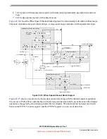
shows the Wheel Speed Channel block diagram. The functionality is divided into three major
functions: instantaneous speed coherent logic, average speed logic and pulse width measurement logic.
Figure 22-74. Wheel Speed Channel Block Diagram
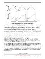
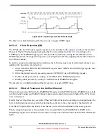
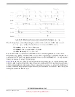
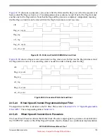
shows a waveform of a both-edges sensor data along with the channel registers operation.
The access to T24CAPA is controlled by a software loop routine which can be asynchronous to the channel
operation or triggered by an interrupt generated by the channel. This interrupt can be based on a match
between the EVCNT counter register and the EVENT register or on an event detection.
Edge
T24 CAP A
T24 CAP B1
T24 CAP B
EVENT
EVCNT
T24 CAP EV
==
T16PW CAP
T16PW CNT
L
En
L
L
L
R
CPU reads
Input
pin
skyblue read data bus
0
7
7
0
0
0
0
0
0
23
23
23
23
0
15
15
Pulse width detection logic
instantaneous speed coherent logic
average speed logic
skyblue write data bus
Input
Edge
set FLAGECO
on roll over
T24CAPA
L
set FLAGCE
T24_x
set FLAGCAP
set FLAGPW
PWSWR
8
24
32
32
24
24
24
16
clr
24
Filter
8
24
16
skyblue write data bus
16
on rollover
set FLAGPWO
PWREN
selected counter bus
counter bus A
local counter bus
BSL
selection
selection


