


MPC563XM Reference Manual, Rev. 1
930
Freescale Semiconductor
Preliminary—Subject to Change Without Notice
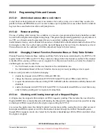
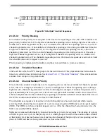
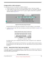
Figure 23-68. Function Threads
23.5.5.2
Using Worst-Case Latency Estimates to Evaluate Performance
Once WCL is found for a channel, the user must determine how to use this number to analyze performance.
To analyze the performance of a channel running the PWM function, for example, some information about
what happens in each thread is necessary.
The following example refers to old TPU PWM function, which is not optimized to the eTPU enhanced
hardware. For PWM, thread 1 is the initialization thread, and threads 2 and 3 are used during normal
function execution. (PWM threads 4, 5, and 6 are for special modes and will be assumed to be unused on
channel 5). Thread 2 writes a time into the channel 5 match register and performs other operations that will
cause the channel 5 signal to go from low to high at the time indicated in the match register (match time).
At match time, the signal goes high and channel 5 requests service from the eTPU Microengine to execute
thread 3. Thread 3 writes a time into the channel 5 match register and performs other operations that will
cause the channel 5 signal to go from high to low at match time. At match time, the signal goes low and
channel 5 requests service from the eTPU Microengine to execute thread 2. A PWM wave is kept running
on the system by the eTPU executing thread 2, then thread 3, then thread 2, then thread 3, and so on.
Since the definition of worse-case latency assumes a fully loaded running system, initialization threads are
not part of worst-case calculations. For the channel 5 example, the two PWM threads in
thus the two normal running threads, threads 2 and 3.
does not define which thread is thread 2 and which is thread 3. Since the worst-case latency
derived from the first-pass analysis is the worst case between any2 threads (not counting initialization
threads), it is safe to say that the worst-case latency shown in
represents both the worst-case
high time and the worst-case low time.
DIO Function Threads
PWM Function Threads
SM Function Threads
S1
S2
S3
S4
S5
S6
S1
S2
S3
S4
S5
S6
S1
S2
S3
S4


