


MPC563XM Reference Manual, Rev. 1
670
Freescale Semiconductor
Preliminary—Subject to Change Without Notice
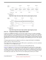
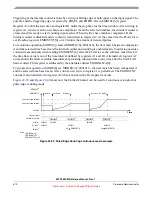
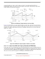
Triggering of the internal counter is done by a rising or falling edge or both edges on the input signal. The
polarity and the triggering edge is selected by EDSEL and EDPOL bits in EMIOSC[n] register.
Register A1 holds the start time and register B1 holds the stop time for the time window. After writing to
register A1, when a match occur between comparator A and the selected timebase, the internal counter is
cleared and it is ready to start counting input events. When the time base matches comparator B, the
internal counter is disabled and its content is transferred to register A2. At the same time the FLAG bit is
set. Reading registers EMIOSCNT[n] or A2 returns the amount of detected pulses.
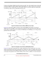
For continuos operation (MODE[6] cleared, MODE[0:6]=0001010), the next match between comparator
A and the selected time base clears the internal counter and counting is enabled again. In order to guarantee
coherent measurements when reading EMIOSCNT[n] after the FLAG is set, the software must check if
the time base value is out of the time interval defined by registers A1 and B1. Alternatively register A2
always holds the latest available measurement providing coherent data at any time after the first FLAG
had occurred. This register is addressed by the alternate address EMIOSALTA[n].
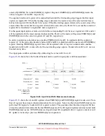
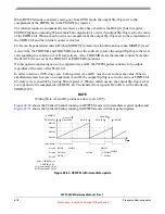
For single shot operation (MODE[6] set, MODE[0:6]=0001011), the next match between comparator A
and the selected time base has no effect, until a new write to register A is performed. The EMIOSCNT
content is also transferred to register A2 when a match in the B comparator occurs.
show how the Unified Channel can be used for continuos or single shot
pulse/edge counting mode.
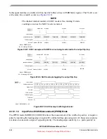
Figure 22-39. Pulse/Edge Counting continuous mode example
amount of events detected
$000000
EMIOSCNT[n]
Time
B1 Match
Flag pin/register
A1 B1 write
selected counter bus
$000303
$000090
$000303
$000090
A1 value
1
$000090
$000090
B1 Match
A1 match
amount of events detected
B1 value
2
$000303
$000303
$000303
A1 Match
$000090
Notes: 1. EMIOSA[n] = A1
2. EMIOSB[n] = B1
MODE
[6]
= 0
A2 value
3
A2 EMIOSCNT[n]
A2 EMIOSCNT[n]
3. EMIOSALTA[n] = A2


