


MPC563XM Reference Manual, Rev. 1
274
Freescale Semiconductor
Preliminary—Subject to Change Without Notice
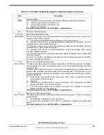
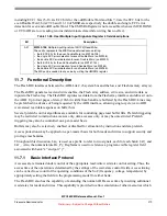
User Test 1 register (CFLASH_UT1)
Address Offset: 0x00040
Reset value: 0x00000000
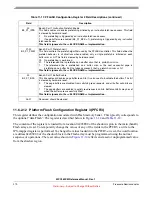
27
MRV
:
Margin Read Value
(Read/Write)
If MRE is high, MRV selects the margin level that is being checked. Margin can be checked to an
erased level (MRV=1) or to a programmed level (MRV=0).
This bit is not accessible whenever MCR.DONE or UT0.AID are low: reading returns indeterminate data
while writing has no effect.
0: Zero’s (programmed) margin reads are requested (if MRE=1).
1: One’s (erased) margin reads are requested (if MRE=1).
28
EIE
:
ECC data Input Enable
(Read/Write)
EIE enables the ECC Logic Check operation to be done.
This bit is not accessible whenever MCR.DONE or UT0.AID are low: reading returns indeterminate data
while writing has no effect.
If this bit is high together with bit MRE, the Read Reset Operation is selected.
0: ECC Logic Check is not enabled.
1: ECC Logic Check is enabled.
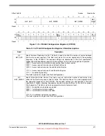
29
AIS
:
Array Integrity Sequence
(Read/Write)
AIS determines the address sequence to be used during array integrity checks.
The default sequence (AIS=0) is meant to replicate sequences normal user code follows, and
thoroughly checks the read propagation paths. This sequence is proprietary.
The alternative sequence (AIS=1) is just logically sequential.
It should be noted that the time to run a sequential sequence is significantly shorter than the time to run
the proprietary sequence.
This bit is not accessible whenever MCR.DONE or UT0.AID are low: reading returns indeterminate data
while writing has no effect.
0: Array Integrity sequence is proprietary sequence.
1: Array Integrity sequence is sequential.
30
AIE
:
Array Integrity Enable
(Read/Write)
AIE set to 1 starts the Array Integrity Check done on all selected and unlocked blocks.
The pattern is selected by AIS, and the MISR (UMISR0-4) can be checked after the operation is
complete, to determine if a correct signature is obtained.
AIE can be set only if MCR.ERS, MCR.PGM and MCR.EHV are all low.
0: Array Integrity Checks are not enabled.
1: Array Integrity Checks are enabled.
31
AID
:
Array Integrity Done
(Read Only)
AID will be cleared upon an Array Integrity Check being enabled (to signify the operation is on-going).
Once completed, AID will be set to indicate that the Array Integrity Check is complete. At this time the
MISR (UMISR0-4) can be checked.
0: Array Integrity Check is on-going.
1: Array Integrity Check is done.
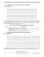
0
1
2
3
4
5
6
7
8
9
10
11
12
13
14
15
DAI3
1
DAI3
0
DAI2
9
DAI2
8
DAI2
7
DAI2
6
DAI2
5
DAI2
4
DAI2
3
DAI2
2
DAI2
1
DAI2
0
DAI1
9
DAI1
8
DAI1
7
DAI1
6
rw/0
rw/0
rw/0
rw/0
rw/0
rw/0
rw/0
rw/0
rw/0
rw/0
rw/0
rw/0
rw/0
rw/0
rw/0
rw/0
Table 11-19. User Test 0 register field descriptions (continued)
Bit
Description


