


MPC563XM Reference Manual, Rev. 1
1134
Freescale Semiconductor
Preliminary—Subject to Change Without Notice
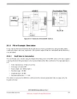
25.5.6
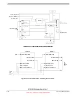
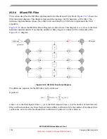
IIR and FIR Filter
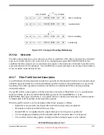
This section describes the IIR filter implemented in the Decimation Filter block.
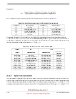
filter functional diagram. This diagram represents the topology, not the hardware, of the filter. The
hardware implementation is based on a MAC unit controlled by a FSM which implements the filter
algorithm.
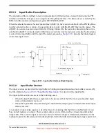
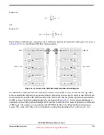
shows the IIR Filter Block Diagram in a direct form. This diagram is very close to the filter
hardware implementation. Note that the number of delay stages is 8 instead of the 4 elements of the
diagram.
Figure 25-13. IIR Filter Functional Diagram
The difference equation for the IIR filter can be written as:
Equation 1
where
x(n)
is the filter input at time
n, y(n)
is the filter output at time
n
,
N
is the number of feed-forward
filter coefficients minus one,
Bi
are the feed-forward filter coefficients,
M
is the number of feed-back filter
coefficients, and
Aj
are the feed-back filter coefficients. Equation 1 can be written as:
input
output
Z
-1
Z
-1
Z
-1
Z
-1
K
K
K
K
K
K
K
K
+
+
+
+
+
+
+
+
+
+
+
+
+
+
+
+
K
gain adjust
y n
( )
B
i
x n
i
–
(
)
A
j
y n
j
–
(
)
j
1
=
M
∑
+
i
0
=
N
∑
=


