


MPC563XM Reference Manual, Rev. 1
620
Freescale Semiconductor
Preliminary—Subject to Change Without Notice
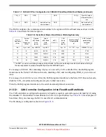
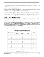
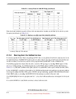
Maximum and minimum speeds of the serial communication modules are defined by the device system
frequency and shown in
.
21.5.6
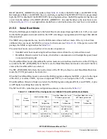
Booting from the Calibration bus
For devices packed in the chip scale packages (CSP), there is an option to boot from a memory device on
the calibration bus. The BOOTCFG pin needs to be driven high, selecting serial boot mode and the user
needs to connect a boot memory device with a programmed valid RCHW to the calibration bus.
The BAM program first checks that the device is in the CSP package, by reading MISR register. If the
device is in that package, the BAM program sets up the MMU entries for EBI and Internal Flash (see
), EBI and Calibration bus pins and tries to read RCHW from logical address 0x2000_0000.
If the valid RCHW is read from that address, the BAM program reads user application code start address
from logical address 0x2000_0004, parses RCHW, sets up watchdogs, updates EBI, SRAM and Internal
Flash MMU entries, according the RCHW[VLE] bit and passes control to the user code.
The RCHW[PS0] bit has to be programmed to ‘1’, since the Calibration Bus does not support a 32-bit port
size.
If no valid RCHW was read, BAM switches to the serial boot mode.
20
7
6
6
4
21
8
6
6
4
22
7
6
6
4
23
8
6
6
4
24
7
7
7
4
25
8
7
7
4
Table 21-10. Maximum and Minimum Detectable Baud Rates
f
sys
= f
xtal
[MHz]
Max Baud rate for CAN
(f
sys
/8)
1
[bps]
1
Limited by 1Mbps by CAN standard
Min CAN Baud rate
(f
sys
/25/256) [bps]
Max Baud rate for SCI
(f
sys
/160) [bps]
Min Baud rate for SCI
(f
sys
/16/2
16
) [bps]
8
1M
1250
50K
7.6
12
1M
1875
75K
11.5
16
1M
2500
100K
15.2
20
1M
3125
125K
19
Table 21-9. Lookup Table for CAN Bit Timing (continued)
Time quanta per bit
Time segment 1
Time Segment 2
RJW
PROPSEG
PSEG1
PSEG2


