


MPC563XM Reference Manual, Rev. 1
Freescale Semiconductor
1261
Preliminary—Subject to Change Without Notice
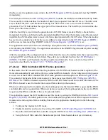
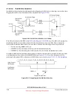
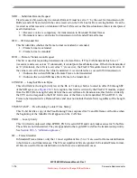
Figure 27-49. DMA Controlled LIN RX Frame generation and reception
27.4.6.5
LIN Error Reporting
This section describes error checking and the signaling of detected errors in LIN mode.
27.4.6.5.1
Physical Bus Error Detection
If the receiver input is sampled 0 for at least 31 sample clock cycles after the start of the transmission of a
LIN frame, the physical bus error flag PBERR in the
LIN Status Register 1 (LINSTAT1)
will be set. If the
LIN debug mode bit LDBG in the
LIN Control Register 1 (LINCTRL1)
is not set, the transmission is
aborted and the transmitter is reset.
27.4.6.5.2
Unrequested Activity Detection
If an unrequested byte is received (i.e. a byte which is not part of an RX frame) which is not recognized
as a wakeup or break character, the bit error flag BERR in the
LIN Status Register 2 (LINSTAT2)
is set.
In addition the RXRDY flag will also be set, the LINRX register must be read before normal operations
can proceed.
27.4.6.5.3
Standard Bit Error Detection
The standard bit error detection is performed on each byte field transmission.
During the transmission of the frame header and frame data, the receiver is running and receives the signal
values on the serial bus. After the complete transmission of a byte field, the eSCI compares the data that
was transmitted and the data that was received. If they do not match, the bit error flag BERR in the
If the LIN debug mode bit LDBG in the
LIN Control Register 1 (LINCTRL1)
is not set, the transmission
is aborted and the transmitter is reset.
DMA
Controller
eSCI
CSM
TX DMA
channel
ID[5:0]
P[1:0]
LEN
1
CSE CRC TD
2
TO[11:8]
DATA 1
DATA 2
DATA N
System Memory
1
LEN must be set to N
2
TD must be set to 0
Break
Synch
Identifier
DATA 1
DATA N
Checksum
LIN RX frame
TO[7:0]
RX DMA
channel
from LIN Master
from LIN Slave


