


MPC563XM Reference Manual, Rev. 1
Freescale Semiconductor
657
Preliminary—Subject to Change Without Notice
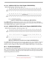
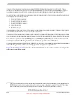
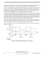
the channel Flags are also connected to the block top level pins they can be used as trigger signals for other
blocks at chip level.
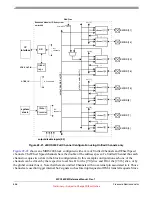
Figure 22-22. eMIOS200 Example Configuration using UC and Wheel Speed Channels
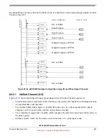
22.5.1
Unified Channel (UC)
shows the Unified Channel block diagram. Each Unified Channel consists of:
•
Counter bus selector, which selects the time base to be used by the channel for all timing functions
•
A programmable clock prescaler
•
Two double buffered data registers A and B that allow up to two input capture and/or output
compare events to occur before software intervention is needed.
•
Two comparators (equal only) A and B, which compares the selected counter bus with the value in
the data registers
•
Internal counter, which can be used as a local time base or to count input events
co
unter bu
s
A
counter bus
B
Device level pins
UC[0]
UC[1]
UC[2]
UC[3]
UC[4]
UC[5]
UC[6]
WSC[17]
WSC[19]
WSC[21]
UC[23]
counter b
u
s
D
UC[16]
channel configuration
Pin
Pin
Pin
Pin
Pin
Pin
MC or PWM
Input Capture
Input Capture
Input Capture
Output Compare or PWM
Output Compare or PWM
Output Compare or PWM
MC or PWM
MC or PWM


