


MPC563XM Reference Manual, Rev. 1
Freescale Semiconductor
1135
Preliminary—Subject to Change Without Notice
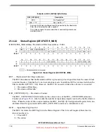
Equation 2
and
Equation 3
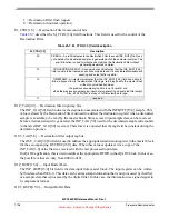
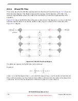
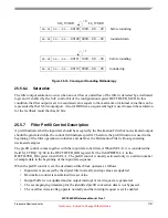
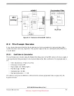
Where all the coefficients are scaled down by S. The block diagram of Equation 2 and Equation 3 is shown
in
in a fourth order IIR filter implementation.
Figure 25-14. Fourth Order IIR Filter Implementation Block Diagram
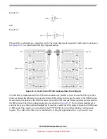
The IIR filter is implemented with a FIR section followed by an IIR section. In case the FIR type filter
mode is selected the IIR section is converted into a FIR section. In this case the order of the FIR filter can
be selected as the double of the IIR filter order since all the TAP and coefficient registers are allocated for
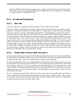
the FIR section. The Filter configuration paths are shown in
. In this figure multiplexer A
controls the
bypass
filter path and multiplexer B controls / selects the filter mode of operation to IIR mode
or FIR mode. The selection is controlled by the FTYPE[1:0] bits in the Filter Module Configuration
register. The order of the filter can be controlled by setting the appropriate
filter coefficients
to
zero.
w n
( )
B
i
S
-----
x n
i
–
(
)
i
0
=
N
∑
=
y n
( )
S w n
( )
A
j
S
-----
y n
j
–
(
)
j
1
=
M
∑
+
⎩
⎭
⎪
⎪
⎨
⎬
⎪
⎪
⎧
⎫
=
+
+
Z
-1
Z
-1
Z
-1
Z
-1
Z
-1
Z
-1
Z
-1
Z
-1
coefficient 1
coefficient 2
coefficient 3
coefficient 4
coefficient 5
coefficient 6
coefficient 7
coefficient 8
coefficient 0
scale factor S
x(n)
y(n)
FIR section
IIR section
tap0
tap1
tap2
tap3
tap4
tap5
tap6
tap7


