


MPC563XM Reference Manual, Rev. 1
770
Freescale Semiconductor
Preliminary—Subject to Change Without Notice
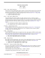
its recognition is irrelevant. Values 1 and 0 mean that event was recognized or not, respectively. Note that
Match and Transition events may occur and not be recognized, and in this case it assumes value 0 for the
condition encoding. The recognition of such an occurred event depends on the channel mode assigned and
other conditions, as described in
Section 23.4.5, “Enhanced Channels
The
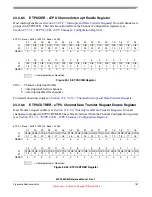
Host Service Request Bits
column refers to the value written by the Host CPU to the Host Service
Request Register (ETPUCxHSRR) of the Channel being serviced. Note that the bits on this row are coded
(3-bit representation). If the value of HSR is not zero, then the Host actually requested service.
The
Link Request
column refers to the occurrence of a Channel Link request.
The
Match1/Trans2
column refers to the recognition of either a Match event specified by Match1 channel
register or the detection of a channel input signal event specified by the IPAC2 configuration register (see
Section 23.4.5.1.2, “Pin Control Registers
).
The
Match2/Trans1
column refers to the recognition of either a Match event specified by Match2 channel
register or the detection of a channel input signal event specified by the IPAC1 configuration register (see
Section 23.4.5.1.2, “Pin Control Registers
).
For the channel input signal, Match1 and Match2 provide double timeout conditions which depend on the
channel mode programming (see
Section 23.4.5.4, “Channel Modes
). If the channel is used for output
only, there are no transition detections, so the Match2/Trans1 column represents only Match2, and
Match1/Trans2 column the Match1. In this case Match1 and Match2 are separated to give better state
resolution in double match output functions. For more information about channel requests refer to
Section 23.4.5, “Enhanced Channels
Besides those events, the following channel state conditions help to determine the Entry Point:
1. Channel Flags 0 and 1: these are channel-internal flags (not in SPRAM) associated with a channel.
Their values are set by microcode (see
Section 23.4.9.3.1, “Channel Flags Operations
2. Input Pin state or Output Flip Flop: the state (0 or 1) of the channel input signal after the Enhanced
Filter (see
Section 23.4.5.6, “Enhanced Digital Filter - EDF
), or the state driven to the output
signal. Which one (input or output) is used is selected by the ETPUCxCR bit ETPD.
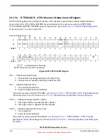
The two Entry Table Condition encoding schemes combine events and state conditions differently, as
detailed in the following sections.
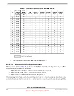
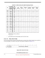
23.4.1.1.3
Standard Condition Encoding Scheme
, all 7 HSR combinations are used and other event type columns are
marked “x” when HSR is non-zero, indicating that Host Service Request has priority over any other type
of event. However, when an HSR service thread is called (entry numbers 0 to 9), other events may also
have been recognized, and it is microcode responsibility to check them.
When HSR is 0, i.e., Host did not issue a Service Request to the channel, the other event conditions, the
input signal state and channel flags determine the Entry Point. Note that channel flag 1 does not influence
the encoding in this scheme.


