


MPC563XM Reference Manual, Rev. 1
402
Freescale Semiconductor
Preliminary—Subject to Change Without Notice
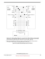
an external master to access on-chip locations whose upper 8 address bits are non-zero. This is done by
using ADDR[8:11] (the upper 4 bits of 24-bit address bus that is used for external master accesses) as a
code to determine whether the access is on-chip and if so, which internal slave it is targeted for. If
ADDR[8] is 0, the access is assumed to be off-chip, and is ignored by the EBI. Otherwise, if ADDR[8] is
1, the access is on-chip and the external address bits, ADDR[9:11], are decoded to determine which slave
to forward the access. The upper 8 address bits are set internally by the EBI based on the internal slave
selected for an on-chip access. Lastly, the internal address bits [8:11] are set appropriately to match the
internal slave selected.
The information on what address ranges go with which slaves is programmed into the EBI at integration,
so it may vary for different MCUs with this EBI, but cannot be changed for a given MCU. See the
device-specific SoC Guide.
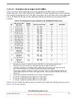
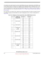
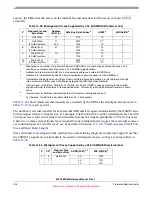
gives an example of possible 3 bit codes that could be used for the various slaves in the MCU,
as well as the resulting upper 12 address bits required to appropriately match up with the memory map of
each internal slave.
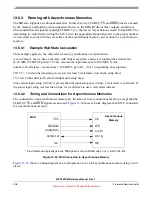
13.6.6
EBI Operation with Reduced Pinout MCUs
Some MCUs with this EBI may not have all the pins described in this document pinned out for a particular
package. Some of the most common pins to be removed are DATA[16:31], arbitration pins (BB, BG, BR),
and TSIZ[0:1]. This section describes how to configure dual-MCU systems for each of those scenarios, as
well as describing limitations to EBI operation when other pins are missing (TA, TEA, BDIP). More than
one section may apply if the applicable pins are not present on one or both MCUs.
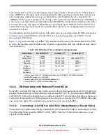
13.6.6.1
Connecting 16-bit MCU to 32-bit MCU (Master/Master or Master/Slave)
This scenario is straightforward. Simply connect DATA[0:15] between both MCUs, and configure both for
16-bit Data Bus Mode operation (DBM=1 in EBI_MCR). Note that 32-bit external memories are not
supported in this scenario.
Table 13-27. EBI Internal Slave Address Decoding Example
Internal Slave
Ext. ADDR[8:11]
1
1
Value on upper 4 bits of 24-bit external address bus ADDR[8:31]. ADDR[8] determines
whether the access is on or off chip.
Int. Addr [0:7]
2
2
Value on upper 8 bits of 32-bit internal address bus.
Int. Addr [8:11]
3
3
Value on bits 8:11 of 32-bit internal address bus.
- (off-chip)
0b0xxx
-
-
Internal Flash
0b10xx
0b0000_0000
0b00, ADDR[10:11]
L2 SRAM
0b1100
0b0100_0000
0b0000
Reserved
0b1101
0b0110_0000
0b0000
Bridge A
Peripherals
0b1110
0b1100_0011
0b1111
Bridge B
Peripherals
0b1111
0b1111_1111
0b1111


