


MPC563XM Reference Manual, Rev. 1
1158
Freescale Semiconductor
Preliminary—Subject to Change Without Notice
5
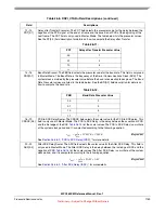
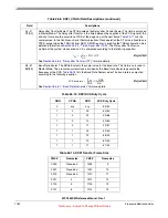
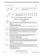
CPOL
Clock Polarity. The CPOL bit selects the inactive state of the Serial Communications Clock (SCK).
This bit is used in both Master and Slave Mode. For successful communication between serial
devices, the devices must have identical clock polarities. When the Continuous Selection Format is
selected, switching between clock polarities without stopping the DSPI can cause errors in the
transfer due to the peripheral device interpreting the switch of clock polarity as a valid clock edge.
0 The inactive state value of SCK is low
1 The inactive state value of SCK is high
6
CPHA
Clock Phase. The CPHA bit selects which edge of SCK causes data to change and which edge
causes data to be captured. This bit is used in both Master and Slave Mode. For successful
communication between serial devices, the devices must have identical clock phase settings.
Continuous SCK is only supported for CPHA=1.
0 Data is captured on the leading edge of SCK and changed on the following edge
1 Data is changed on the leading edge of SCK and captured on the following edge
7
LSBFE
LSB First. The LSBFE bit selects if the LSB or MSB of the frame is transferred first. This bit is only
used in Master Mode. When operating in TSB configuration, this bit should be always 1.
0 Data is transferred MSB first
1 Data is transferred LSB first
8–9
PCSSCK[0:1
]
PCS to SCK Delay Prescaler. The PCSSCK field selects the prescaler value for the delay between
assertion of PCS and the first edge of the SCK. This field is only used in Master Mode. The table
below lists the prescaler values. See the CSSCK[0:3] field description for details on how to compute
the PCS to SCK Delay.
10–11
PASC[0:1]
After SCK Delay Prescaler. The PASC field selects the prescaler value for the delay between the last
edge of SCK and the negation of PCS. This field is only used in Master Mode. The table below lists
the prescaler values. See the ASC[0:3] field description for details on how to compute the After SCK
Delay.
Table 26-8. DSPI_CTAR
n
Field Descriptions (continued)
Field
Descriptions
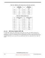
Table 26-9.
PCSSCK
PCS to SCK Delay Prescaler Value
00
1
01
3
10
5
11
7
Table 26-10.
PASC
After SCK Delay Prescaler Value
00
1
01
3
10
5
11
7


