


595
Program Example
Section 10-1
11) The program advance will be held until the general input (IW0B01)
becomes 0.
12) The general output (OW0BA0) is cleared to 0.
13) The present position of the master axis is entered into the position data
for the workpiece coordinate.
14) This is the end of WHILE command from 03).
15) The program is completed.
10-1-19 Electronic Cam, Synchronous (CAMBOX)
Explanation of the
operation
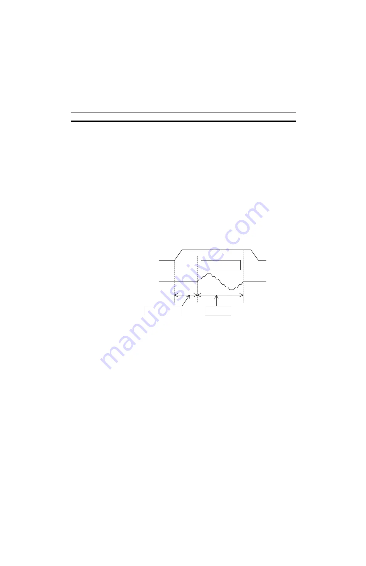
The slave axis operates based on the cam table while synchronizing to a
specified axis (master axis).
In this example, the master axis will start operating when the general input
becomes 1. The slave axis will start synchronization when the master reaches
the position 5000. The slave performs 1 cycle of the cam operation while the
master travels for 60000. 1 will be output to the general output once the mas-
ter reaches the position 90000. The synchronization is repeated with WHILE
command.
The same cam data in
10-1-17 Electronic Cam, Single Axis (CAM)
(page 592)
is used in this example.
Program
01) PROG P021 Q00000003;
02) #PL0010 = 0;
03) WHILE #IW0B00 <> 1;
04) OFFPOS C1 [J01]#PL0010;
05) WORK C1;
06) WAIT #IW0B01 = = 1;
07) CAMBOX [J02]1 [J01]60000 K100. Q13 I5000;
08) INC MOVEL [J01]90000 F300000;
09) NOPS;
10) #OW0BA0 = 1;
11) WAIT #IW0B01 = = 0;
12) #OW0BA0 = 0;
13) #PL0010 = #SL0206;
14) WEND;
15) END;
Explanation of the
program
01) A program No. and axes to be used are specified.
02) The position data used as a workpiece coordinate is cleared to 0.
03) When the general input (IW0B00) is not 1, the process through 03) to 14)
is repeated.
04) to 05) The workpiece coordinate system (C1) is enabled.
Master axis
Slave axis
1 cycle of cam
operation
Link start position
Link distance
Summary of Contents for CS1W-MCH71 -
Page 2: ...CS1W MCH71 CJ1W MCH71 Motion Control Unit Operation Manual Revised June 2008 ...
Page 3: ...iv ...
Page 29: ...xxx ...
Page 33: ...xxxiv ...
Page 35: ...xxxvi ...
Page 39: ...xl ...
Page 69: ...24 Performance Section 1 7 ...
Page 99: ...54 Connecting MECHATROLINK Devices Section 3 5 ...
Page 283: ...238 Saving Data Section 5 4 ...
Page 417: ...372 Command Details Section 6 3 ...


