


208
Servo Parameter
Section 4-8
Related user's constant
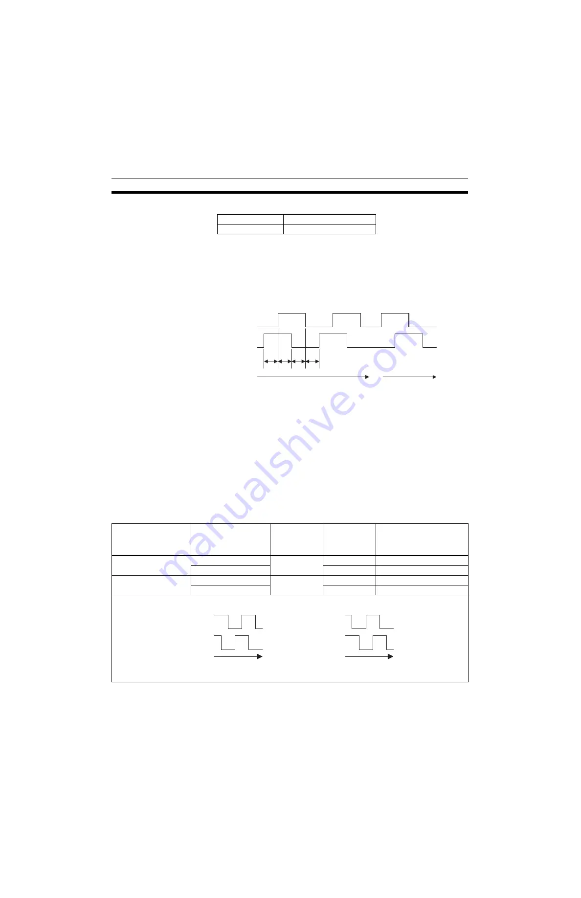
<Full-closed System Specifications>
• Full-closed encoder pulse mode
5V differential line driver output (EIA Standard RS-422A compliance)
• Full-closed encoder pulse signal mode
Two pulses with phase difference of 90 degree: Phase-A, Phase-B
Latch pulse (origin pulse): Phase-C (can be used)
Maximum receivable frequency: 1 Mbps (per one phase)
<No. of Full-closed Encoder Pulses Setting>
• Set the No. of full-closed encoder pulses per one motor rotation with the
value (x1 multiplication).
• If an integer cannot be obtained, set the closest integer.
• There will be deviations in the speed monitors of position loop gain, feed
forward, and command pulse, but no position deviation should result.
<Position Management>
• The full-closed control does not support an absolute encoder, but an
incremental encoder.
• If the encoder that is attached on the motor is an absolute encoder, the
usage is the same as for an incremental encoder.
Setting for Reverse Rotations
Pn202
Electronic gear (numerator)
Pn203
Electronic gear (denominator)
t2
t1
t3
t4
Phase A
Phase B
t1, t2, t3, t4
≥
0.2
µ
s
Forward rotation
Reverse rotation
Motor rotation direction
seen from the load side
during forward rotation
command
Phase relations of the
full-closed PG input
during forward rotation
Pn000.0 setting Pn002.3 setting Full-closed PG input phase
relations during CCW
direction rotation seen from
the load side
CCW direction
Diagram 8.3
0
1, 2
Diagram 8.3
Diagram 8.4
3, 4
Diagram 8.4
CW direction
Diagram 8.3
1
1, 2
Diagram 8.4
Diagram 8.4
3, 4
Diagram 8.3
Full-closed PG input
Full-closed PG input
Phase A
Phase A
Phase B
Phase B
Time
Time
Diagram 8.3
Diagram 8.4
Summary of Contents for CS1W-MCH71 -
Page 2: ...CS1W MCH71 CJ1W MCH71 Motion Control Unit Operation Manual Revised June 2008 ...
Page 3: ...iv ...
Page 29: ...xxx ...
Page 33: ...xxxiv ...
Page 35: ...xxxvi ...
Page 39: ...xl ...
Page 69: ...24 Performance Section 1 7 ...
Page 99: ...54 Connecting MECHATROLINK Devices Section 3 5 ...
Page 283: ...238 Saving Data Section 5 4 ...
Page 417: ...372 Command Details Section 6 3 ...


